Worm gearing . at the number of threads on a wormhas the following relation to its pitch line diameter. nd = nP cot a (3) Tzd .. n = ^—.— (4) P cot a ^ ^ and to find the number of threads, it is first necessary to knowthe value of the lead angle a which again depends upon thelead L, and this in its turn upon the gear ratio required.The gear ratio G has the following value ttD ^-L (5) hence ,. ^D ^ G (6) and the lead angle a is such that tan a— ,m (7) Substituting from equation (6) nD G tan « = —Tnd 7:0 D tan a- ^^ (8) from which a is at once found, and from this the value of n (equation 4). D
Image details
Contributor:
The Reading Room / Alamy Stock PhotoImage ID:
2AM80HMFile size:
7.2 MB (185.7 KB Compressed download)Releases:
Model - no | Property - noDo I need a release?Dimensions:
1826 x 1369 px | 30.9 x 23.2 cm | 12.2 x 9.1 inches | 150dpiMore information:
This image is a public domain image, which means either that copyright has expired in the image or the copyright holder has waived their copyright. Alamy charges you a fee for access to the high resolution copy of the image.
This image could have imperfections as it’s either historical or reportage.
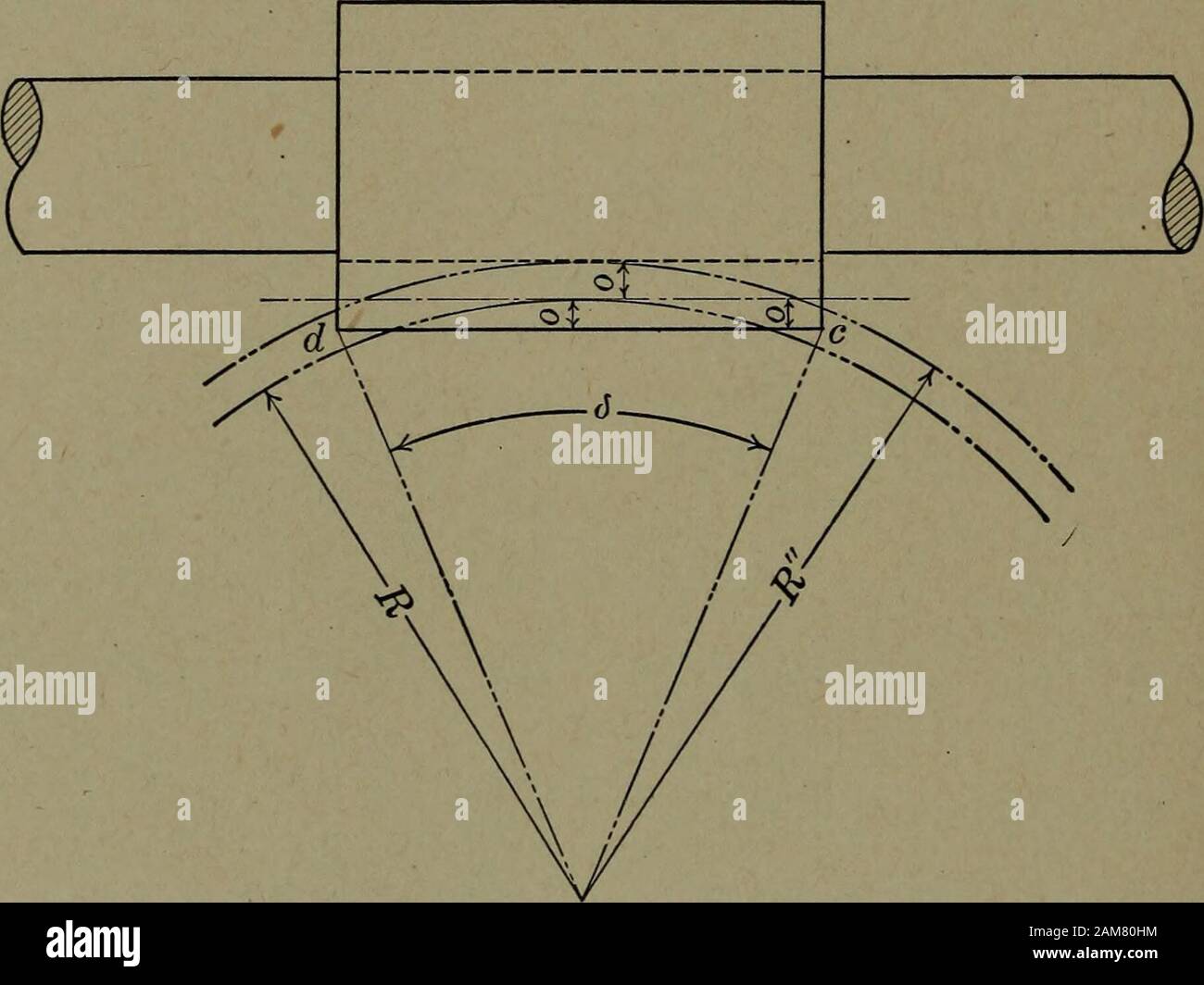
Worm gearing . at the number of threads on a wormhas the following relation to its pitch line diameter. nd = nP cot a (3) Tzd .. n = ^—.— (4) P cot a ^ ^ and to find the number of threads, it is first necessary to knowthe value of the lead angle a which again depends upon thelead L, and this in its turn upon the gear ratio required.The gear ratio G has the following value ttD ^-L (5) hence , . ^D ^~ G (6) and the lead angle a is such that tan a— , m (7) Substituting from equation (6) nD G tan « = —Tnd 7:0 D tan a- ^^ (8) from which a is at once found, and from this the value of n (equation 4). DETERMINATION OF LENGTH OF WORM AND NUMBER OF TEETH IN CONTACT The worm and worm wheel may be regarded as two cylinderswhich cut one another, their axes being at right angles. 18 WORM GEARS In Fig. 3, which is a section through the axis of the worm, theHne dc represents the hmiting surface of the worm; o is theaddendum of the teeth. R^, the radius of the hmiting circle of the worm wheel, isequal to R+o.. Fig. 3. The total height of the wheel teeth cutting the cylinder of theworm is 0 +0, and this is also the versin of the angle-. Therefore, Again, 2X0 b R- = ^^^^^^ 2 dc = 2 sin- d , . the length oi dc = 2 R sin ~=g (9) Since the teeth of the wheel are hobbed, it follows that everyspace between the worm threads has a wheel tooth corre-sponding to it and some portion of this is in contact with athread of the worm. The number of threads is ^ (10) PRELIMINARY PROPORTIONS 19 and this is the number of teeth in contact at all times. Letthis =n Then, n=| (11) Substituting for g, 2R sin^ 2 (12) n P Up to this point we have considered the method of determin-ing the following: Pitch of the wheel teeth, Diameter of worm, Diameter of worm wheel. Lead angle, Number of worm threads. Length of worm.The centers of the worm and wheel are evidently expressedby the following c = —2— (13) and having thus settled the leading dimensions, we are in aposition to investigate the correct form