. The Bell System technical journal . amounts ofdelay and attenuation. The first three pictures of Fig. 10 were taken with the path lengthsexactly equal. When the amplitudes were also equal there was completecancellation. As the signal in one branch was attenuated the amplitudeof the resultant pulse increased until it became equal to that of theoriginal pulse as shown in the third pictiue. Increasing one path by one-half wavelength brought the signals from the two branches into phaseand they added up to double amplitude as seen in the fourth picture. Itshould be pointed out that although in ou
Image details
Contributor:
Reading Room 2020 / Alamy Stock PhotoImage ID:
2CRTR46File size:
7.2 MB (389 KB Compressed download)Releases:
Model - no | Property - noDo I need a release?Dimensions:
2268 x 1102 px | 38.4 x 18.7 cm | 15.1 x 7.3 inches | 150dpiMore information:
This image could have imperfections as it’s either historical or reportage.
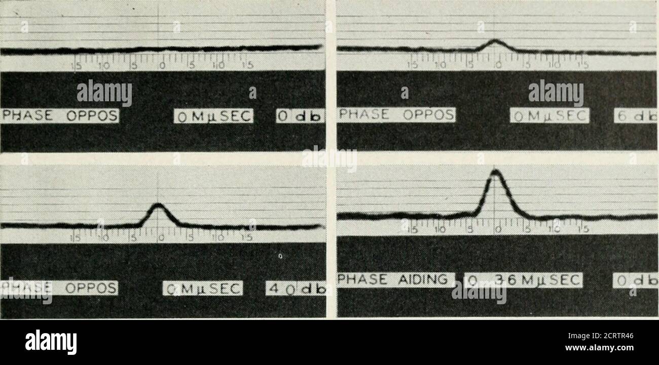
. The Bell System technical journal . amounts ofdelay and attenuation. The first three pictures of Fig. 10 were taken with the path lengthsexactly equal. When the amplitudes were also equal there was completecancellation. As the signal in one branch was attenuated the amplitudeof the resultant pulse increased until it became equal to that of theoriginal pulse as shown in the third pictiue. Increasing one path by one-half wavelength brought the signals from the two branches into phaseand they added up to double amplitude as seen in the fourth picture. Itshould be pointed out that although in our experiment we changed delayby 0.36 millimicroseconds in going from the fiist minimum to the firstmaximimi, in free space a change of delay of only 0.125 millimicroseconds SIDE ARM A--> /W^ ATT E N U ATORE PLANE ARM J Nk. H PLANE ARM PLUNGER A PULSE INPUT OUTPUTTO DETECTOR -//V/AT T E N U ATO R SIDE ARM B--> PLUNGER B Fig. 9—Apparatus to simulate two-path transmission. PROPAGATION STUDIES AT MKUOW AVI-; FUlXjlTKNCIKS 101. Fig. 10—Simulated two-path transmission. would be rec[iiired. The discrepancy lies in the large ratio between thephase elocity and group velocity in the wave guide used whereas infree space this ratio is, of course, ec^ual to unity. In free space the amountof delay rec^uired to go from a maximum to a minimum signal correspondsto a change of path difference of only about one and one-half inches.With only this slight shift rec^uired to change conditions from those shownIn the first picture of Fig. 10 to those shown by the last, it is not at allsiuprising that the received signal is very unstable during time of multi-path transmission. Fig. 11 shows the effect of changing relative phases in 90° steps whilekeeping the amplitudes equal to each other. It is seen that even with thecarriers in direct opposition cancellation is far from complete due to the •^ ^NwijiiW