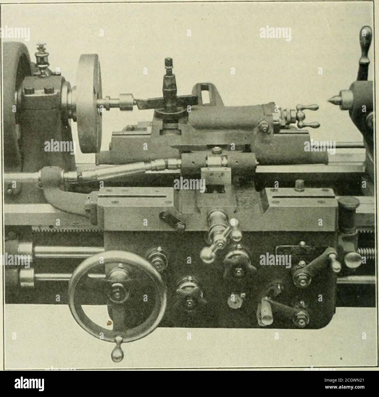
. American engineer . ven through achange gear mechanism supported by a bracket at the frontof the headstock. The gear train has a small ciuadrant thatis used to disengage the drive when not required. Power istaken from a spur gear on the end of the spindle and is trans-mitted through the change gear mechanism to the drivingshaft wdiich is journaled in a suitable bracket fastened tcthe left end of the carriage. Between this bracket and thetool rest are the universal joints which permit the cros.smovement of the tool slide. The driving shaft revolves con-stantly in one direction until the direc
Image details
Contributor:
Reading Room 2020 / Alamy Stock PhotoImage ID:
2CGWN21File size:
7.1 MB (274.9 KB Compressed download)Releases:
Model - no | Property - noDo I need a release?Dimensions:
1597 x 1564 px | 27 x 26.5 cm | 10.6 x 10.4 inches | 150dpiMore information:
This image is a public domain image, which means either that copyright has expired in the image or the copyright holder has waived their copyright. Alamy charges you a fee for access to the high resolution copy of the image.
This image could have imperfections as it’s either historical or reportage.
. American engineer . ven through achange gear mechanism supported by a bracket at the frontof the headstock. The gear train has a small ciuadrant thatis used to disengage the drive when not required. Power istaken from a spur gear on the end of the spindle and is trans-mitted through the change gear mechanism to the drivingshaft wdiich is journaled in a suitable bracket fastened tcthe left end of the carriage. Between this bracket and thetool rest are the universal joints which permit the cros.smovement of the tool slide. The driving shaft revolves con-stantly in one direction until the direction of the spindle isreversed at which time it ceases to operate. This valuablefeature results from the use of a clutch between the camand the driving shaft which is operative in one direction only. There are three cams provided in addition to thechange gears, giving the attachment an extremely widerange. The cams run in an oil bath and are located directlyin front of the tool slide, permitting them to be readily in-. American Uathe, Showinq End Relief Attachment. terchanged. Possibly the most important and valuable feat-ure of this new attachment is that which permits the toolslide to be operated at every 30 degrees, thus providingtwelve operating positions within a circle. This permits the