. Graphic statics, with applications to trusses, beams, and arches. Fig. 54. due to a vertical load of 20000 lbs. uniformly distributed overthe roof surface, together with a normal wind load of 12500 lbs.on the inclined roof surface. Also determine the direct stressesin all the members of the frame. Assume the columns to behinged at the base. ROOF-TRUSSES. 95 4. Solve Problem 3, assuming the columns to be fixed at thebase. 68. Sway-bracing. Illustration. The frame (Fig. 55) ismade up of a number of transverse frames or bents, braced so asto resist distortion of any kind. Each bent is composed
Image details
Contributor:
Reading Room 2020 / Alamy Stock PhotoImage ID:
2CEMEYMFile size:
7.2 MB (208.7 KB Compressed download)Releases:
Model - no | Property - noDo I need a release?Dimensions:
1652 x 1513 px | 28 x 25.6 cm | 11 x 10.1 inches | 150dpiMore information:
This image is a public domain image, which means either that copyright has expired in the image or the copyright holder has waived their copyright. Alamy charges you a fee for access to the high resolution copy of the image.
This image could have imperfections as it’s either historical or reportage.
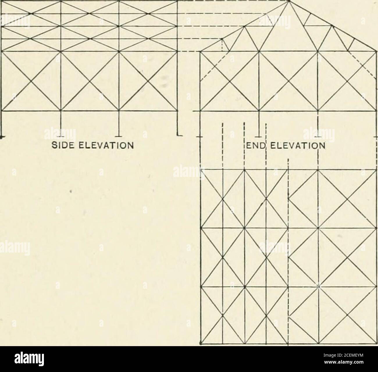
. Graphic statics, with applications to trusses, beams, and arches. Fig. 54. due to a vertical load of 20000 lbs. uniformly distributed overthe roof surface, together with a normal wind load of 12500 lbs.on the inclined roof surface. Also determine the direct stressesin all the members of the frame. Assume the columns to behinged at the base. ROOF-TRUSSES. 95 4. Solve Problem 3, assuming the columns to be fixed at thebase. 68. Sway-bracing. Illustration. The frame (Fig. 55) ismade up of a number of transverse frames or bents, braced so asto resist distortion of any kind. Each bent is composed of a. UPPER ; LOWER CHORD BRACING CHORD BRACING Fig. 55. truss supported on columns, the truss and columns being bracedtogether as shown in the end elevation. In the intermediatebents knee-braces, shown by the dotted lines, are commonlyused; while at the ends two intermediate columns are shown, the bracing for these consisting of diagonal tension-rods andhorizontal struts. The bents are braced together by (1) diagonaltension-rods in the plane of the upper chords, the purlins servingas struts; 12) diagonal tension-rods in the plane of the lower 96 GRAPHIC STATICS. chords; (3) diagonal tension-rods in the sides of the buildingbetween the columns. Such a system of bracing as described aims to prevent dis-tortion of the individual bents, and to keep the various bents ver-tical and in line, under the action of any horizontal force suchas wind on the side or end of the building, the pull of belts, thrust of jib-cranes, etc. The particular system of bracing em-