Skip navigation

Category Archives: classic computers

(right-clicking on any image and choosing “view image” will enlarge image)

Todays article we will be looking at the short lived Apple eMate 300. Apple’s late 90’s attempt to fuse the Newton PDA and laptop.

I won’t be taking this unit apart mostly for the reason of I do not actually own this machine and I’m borrowing it, thus I don’t want to risk accidentally damaging it seeing as I’m not very familiar with laptops and such nor do they particularly interest me. that said I didn’t want to pass up an opportunity to feature this interesting and kind of rare machine.

The eMate 300 was briefly sold for less then a year between 1997 and 1998, mostly to the educational market.

The eMate 300 comes in an all translucent green case and If I’m not mistaken is the first Apple computer to use the colored plastic motif that the later iMacs became so well known for. The plastic has actually held up fairly well over time and did not seem brittle to me.

Another thing you may notice is the eMate 300 kind of looks like a butt in tight green spandex. I’ve also been told it looks like a bust line, just the image you want to evoke for a device meant for the educational market…

Lets take a quick look at the specs for the eMate. The screen is a 480×320 resolution grayscale that operates as a touch screen with the use of the stylus. It does have a backlight that can be toggled on and off via a button on the keyboard and sort of resembles the look of the screen on the original Gameboy with the green soup look although the eMate screen does look much better.

There are some nice touches like the holes to place your stylus on either side of the eMates keyboard.

The CPU is a 25MHz ARM 710a RISC processor and the machine comes with 3MB of RAM standard. In a world with several hundred Megahertz Pentium and K6 CPU’s this feels like an extremely underpowered processor in 97/98 but remembering this was not meant to be an actual laptop but a beefed up PDA the power is acceptable for most tasks as far as I could see. Under the battery door there is an expansion slot that did make the RAM expandable via third party cards. There is also a headphone jack and PCMCIA slot on one side so adding things such as wireless and flash memory is possible.

On the opposite side of the eMate is a small sliding panel door that acts as a cover for Macintosh serial/localtalk ports.

Unfortunately I don’t have much else to say about the eMate. It seems like it was a good idea at the time but it never really caught on and sold very well. You could also at the same time buy the more traditional looking Apple Messagepad 2000 which was a more powerful and expandable PDF device.

As far as I know there are no games for the eMate 300 which makes sense as that was not it’s intended use nor does it even sport USB ports or floppy and/or CD drives to help facilitate such things. I did have some fun just mucking around on it. There are some neat features like the art program which lets you draw free form shapes and then the eMate sort of fixes them up. For instance I could draw a rough circle or triangle and the eMate would then adjust my hand drawn shapes to perfect circles and triangles. It was also neat to hand write sentences and then have the eMate transfer the hand written notes into text, although it didn’t always get things right.

Again, The eMate is a neat and pretty rare piece of Apple and computing history but it isn’t really my personnel cup of tea.

(right-clicking on any image and choosing “view image” will enlarge image)

I’ve always liked the Vectra line. I don’t exactly know why as I never owned one and they tended to be meant for more of the business side of computing then gaming or home use but none the less I still always kind of had a soft spot for the series.

Today we are going to look at the HP Vectra XA, a decidedly business oriented model that still can make a great retro PC with some slight tweaking.

On the far right of the Vectra XA we have one 5 1/2 expansion bay as well as two 3 1/2 bays. The bays though are a little different in that the two 3 1/2 bays sandwich the single 5 1/4 bay. The dual 3 1/2 bays also are not centered like you see in most cases but are in these sort of extended bays with plastic tabs covering the unused portion. It almost looks like if you removed everything you could turn it into a dual 5 1/4 bay but that doesn’t really work. These bays also use rails to secure the drives, yuk.

In the center we have a removable plate (when the case is open) which has our buttons and LED lights. starting on the top left we have a power button followed by a reset button and finally we have a “lock” button. This button when pressed would suspend the system until you entered a passcode. Handy if you were walking away from your desk and didn’t want nosy coworkers, children or perhaps spouses poking around. Mine didn’t seem to work which is probably for the best since I don’t have a passcode. There may be an option in the BIOS to enable this feature though I didn’t see it when I quickly checked.

Below this we have a hard drive activity light as well as a LAN network activity light. Some models came with an audio board and had audio jacks and volume controls on the under the LED lights but mine did not.

On the back starting on the left we have a security lock and under that a special built-in network card featuring a 10T and 100T Ethernet jacks.

Here is a look at that card installed from the side.

To the right of the Ethernet card we have four expansion slots and several clearly labeled built-in I/O ports. We have a parallel printer port as well as a single USB 1.1 port sandwiched between two serial ports. Finally we have dual PS/2 ports for mouse and keyboard. There is an option in the BIOS for this model to power on via pressing the space bar on the keyboard but I couldn’t get it to work on my machine even with the BIOS option enabled. A specific HP keyboard may be required for this function to work.

removing the top to the case is fairly simple and only involves sliding these plastic tabs located on the bottom front of the case.

After this just pull the case lid forward and up to remove.

Here we see the XA with the top of the case removed.

The hard drive is located behind the front drive bays and is secured upside down to a metal bracket hanging over the network card. The hard drive installed in my XA was a 1.6GB Quantum Fireball.

Now let’s take a look at the motherboard with all those expansion cards out of the way.

1 ) CPU – The Vectra XA uses a socket 7 motherboard. Mine came with an Intel 166MHz MMX CPU installed.

The 166MHz Pentium is a classic CPU and perfect for early Windows and late DOS retro machines. The XA should be able to support every CPU from the Intel 75 up to the 233 MMX as well as Cyrix and AMD equivalents. There is no fan on the heatsink since the CPU gets its active cooling from a fan located on the power supply. We will take a closer look at this later.

2 ) Voltage Regulator – It was pretty common for motherboards of this era to have voltage regulator modules. Rather than having the voltage regulator soldered onto the board it was sometimes on a removable module. In theory you could replace the module much easier if it should fail or even swap it out for one that supported different voltages. They tend to be pretty difficult to come across these days.

3 ) Cache Module – Located between the main system RAM and the CPU, the XA uses a pipeline burst COASt module or Cache On A Stick to provide level 2 cache memory. The cache stick in my XA is a 512kb module though a 256kb can be swapped in if you wanted to for some reason.

4 ) RAM – The XA has six 72-pin RAM slots accepting a total of 192MB of RAM. My PC came with 48MB installed

5 ) CMOS battery and switch box – The CMOS battery for the Vectra XA is a BR2325 coin battery as opposed to the more common CR2032 batteries most motherboards tend to use. The BR is slightly larger than the CR and there are some differences as far as battery life but that is beyond the scope of this article.

The switch is mostly used for setting the front side bus and CPU frequency.

6 ) Power supply – The XA power supply is a fairly low power 100w proprietary form factor power supply. To make it even worse the board requires an AUX power connector from the supply and a specifically positioned fan on the underside of the power supply is used to cool the CPU heatsink.

Replacements can be found on eBay but the asking price of these is usually more then what one is likely to purchase the computer for.

Next to the main AT power connector is a floppy drive connector and dual EIDE connectors for attaching hard drives, CD-ROM drives, ect.

Video – The XA does not have built-in video but it did come standard with a discrete PCI Matrox Millenium video card. This card makes sense seeing as the Vectra XA was aimed at business. The Millenium offers excellent image quality for the time. For gaming is offers fast speeds and decent compatibility.

Sound – The sound card that came with my XA is a Sound Blaster 16 with the Vibra16S sound chip. In my opinion the Vibra cards are a little less noisy then early SB cards but they may not sound quite the same. This card also does not have a true FM OPL chip but instead uses a CQM synthesis chip for FM.

The final card that came installed with my XA is some kind of HP branded interface card with an HP-IB aka IEEE-488 interface.

The HP Vectra XA is a pretty decent socket 7 machine and is fairly easily customizable for your retro needs. It can make a great retro game rig with the right video and sound cards. I’d of preferred two 5 1/4 expansion bays as opposed to one and the two 3 1/2 bays but that’s a minor gripe. The biggest weakness of the XA in my opinion (and most of the Vectra line of this period) is the proprietary form factor of the power supply. If your supply dies it does make things a little more difficult as far as replacements go.

(right-clicking on any image and choosing “view image” will enlarge image)

We’ve seen a lot of PC’s on this blog over the years from companies that you normally would not associate with the computer market attempting to get a slice of that yummy yummy PC market pie. Today we’re going to take a look at one from the Korean car manufacturer Hyundai.

Hyundai is mostly known for cars, at least here in the USA, but like so many others they actually had a line of IBM PC compatibles. Today we will be taking a look at one PC out of that line, the Super-16 Turbo. You may make the assumption like I did that this is going to be a 16MHz 286 based machine, but nope. The Super-16 Turbo is a completely bland, middle of the road but reliable and functional 8088 PC.

My Super-16 Turbo here has some uneven yellowing going on with the left side being noticeably darker than the right. The front of the PC is pretty bare bones. We just have the Hyundai badge on the left and duel 5 1/4 bays to the right. My machine came with a single 360KB 5 1/4 inch floppy drive (The original drive i’m told was also a 360KB drive but was belt driven and had a round LED) as well as a 30MB MFM hard drive mounted in the lower bay.

Completing the front face of the PC is a large block of a power button and a power LED light.

A PC style keyboard connector is located on the right side of the machine.

The rear of the Super-16 is pretty sparse mirroring the front. We do get a nice power pass though for a monitor which is always nice but as far as built in ports go all we get is a RS-232C serial port as well as a printer port. To the right are six slots for expansion cards.

The top of the case comes off after unscrewing two screws on each side as well as one screw on the rear of the case.

Here we have the motherboard with the expansion cards removed.

1 ) CPU – The CPU is a P8088-2 running at 8MHz though I’ve seen variations of this PC that used an 8088-1 at 10MHz. This is pretty fast for an 8088 CPU and allows some more versatility when playing some later CGA titles or titles that may chug just a bit at 4.77MHz. The problem with the Super-16 Turbo is that there does not seem to be a turbo button to switch CPU speeds between 4.77MHz and 8MHz nor can I find a keyboard command to switch between speeds. There is a DIP switch setting though on the large blue switch located on the motherboard to choose between speeds but unless your playing with the case off this is extremely inconvenient. I’ve been told by a user of this machine that originally the machine came with a TURBO.EXE program and hitting Ctrl+Alt+Enter on the keyboard would toggle speeds.

If there is a way to switch speeds with the cover on and I’m just not seeing it that makes the Super-16 Turbo a pretty nice XT PC as far as versatility goes with those old CGA games but if the only way to change speeds is the internal switch then that really handicaps the Super-16 as you have to choose between being more compatible with very early games or not.

Another big downside with this PC and a hallmark of cheapness is that the CPU is soldered onto the board. That means without removing the motherboard and desoldering the old CPU you can not swap the CPU for a faster 8088-1 or NEC V20 or easily change CPU’s in case yours fails.

Next to the CPU is an empty socket so you can add an 8087 math co-processor if desired though these rarely add much benefit on an XT class PC outside of a few select games and CAD software.

2 ) RAM – The Super-16 Turbo comes stock with 640KB soldered onto the motherboard. This is nice but by the time this machine came out this was standard. You can, of course, add more memory via an 8-bit ISA expansion card though even with an 8MHz 8088 your really not going to be playing any games that really require that much memory or at least not playing any that run all that ideally.

The motherboard itself is fairly compact for an XT board and has six expansion slots which should be enough for most XT class user’s needs. The floppy controller is built into the motherboard freeing up a potential expansion slot and there is a real cone speaker although its located sort of awkwardly in the center of the case further to the rear.


I do like that the CMOS battery on this board is a coin battery rather than a barrel one which not only makes it a little easier to replace but has less chance of leaking on your board and destroying components over time.

The large blue switch to the right of the battery sets things like your CPU speed, whether you have a math co-processor installed and video mode. You can find a layout of the motherboard as well as the switch settings Here.

Let’s take a quick look at the two expansions cards that came with my Super-16 Turbo PC

The first card was an 8-bit MFM hard disk controller from WDC which was attached to my PC’s 30MB ST-238R hard drive. On boot, the hard drive did in fact spin up but the machine would not boot from the HDD. If I booted from a floppy disk into DOS I was able to access the hard drive so maybe this drive was just used to store data and not set up as a bootable drive on my machine.

The second card installed was the video card.

The video card is a 64KB ATI Graphics Solution Plus 8-bit CGA card. This is an earlier card but like most of ATI’s video cards is supports Plantronics and Hercules graphics modes along with standard CGA modes. There is no color composite jack on this card though I see some headers on the top of the card near the video output which may allow one to connect a dongle.

The Hyundai Super-16 Turbo seemed to of been released in the latter half of the 1980s as a sort of budget machine competing against more capable but also more expansive 286 and even 386 PCs. Reading a few Computer magazine articles of the time that mention the Super-16 seems to paint it as a no thrills but reliable PC and thats mostly the impression I get. Corners were obviously cut on this machine and it does have a sort of boring utilitarian feel about it but it also does seem to be pretty reliable overall.

There isn’t a whole lot of bells and whistles built into this PC. The CPU is soldered to the board and the fact that you seemingly cannot switch CPU speeds without opening the case is a real pain but at the time if you just wanted a basic and cheap PC for the home that just worked I guess this would have been a nice compact choice. As a retro gaming PC though, if you find one cheap and don’t have a PC of this era go ahead and pick it up but otherwise there are more versatile PC’s of this era out there.

In 2002 Apple released the successor to their all-in-one computer, the iMac G3. Originally named the “New iMac” the PC would eventually be known as the iMac G4. The iMac G4 was extremely futuristic looking for it’s time with the entire motherboard and other components being housed inside a dome case. Coming out of the top of this dome was an adjustable metal arm and a TFT active matrix LCD screen with a native resolution of 1024 x 768. This was still a era of large heavy CRT monitors and seeing an LCD still felt pretty futuristic. In today’s article we will be looking at the 800MHz model which is the second of the four revisions Apple made of the iMac G4.

Even if your not an Apple fan you have to appreciate the industrial design and ability to fit everything into a small 10.6″ dome case. Even in 2019 as I write this article the iMac G4 wouldn’t look out of place on a sci-fi TV series taking place in the future home or on a starship.

Of course there is a price for this compactness and design and I’m not talking the dollar amount Apple wanted for one. I’m talking about expandability which is obviously severely lacking with the G4.

The front of the dome has no visible buttons or LEDs, just a shiny Apple logo and a slot for the optical drive. The optical drive in my model is a CD-R / DVD combo drive but the drive did vary by model.

Side shot

Full rear shot

On the back of the dome we have an array of different connections for connecting your G4 to the internet as well as other peripherals.

All the way, barely visible, on the left side we have a Kensington security lock for securing your iMac to some object so whomever doesn’t walk away with it. Next to this we have a standard 3.5mm headphone jack. The next jack looks to be another standard 3.5mm audio jack but it is not. This is actually a special audio jack for a set of Apple Pro speakers. The jack is a little smaller then a standard 3.5mm jack and it also delivers power to the speakers. I unfortunately do not have a pair of these speakers but many consider them some of the best speakers ever made for any Mac computer. Following this we have two firewire 400 ports and an Ethernet jack. In the center we have a three pin power connector followed by a modem, three USB 1.1 ports and finally a mini VGA output port. The port supposedly only mirrors the main display but still handy if your having issues with the built in monitor.

To access the internals of the iMac there are four small screws on the underside of the base.

Removing the metal base plate gives access to the airport wireless card, or if you don’t have one, the port to install it. To the right is a 144-pin SO-DIMM RAM slot. This RAM is the smaller style SDRAM more commonly found in things like laptops. This slot will accept up to a 512MB stick of PC133 memory which is what I have currently installed. The iMac G4 can accept up to 1GB or RAM total but the second RAM slot is not as easily accessible. Later versions used DDR memory and had a maximum limit of 2GB..

After removing several more screws on the base of the G4 you need to carefully pry the two pieces apart. Even with the screws removed it may take some effort as there should be thermal paste still bonding the two haves of the case together.

Here are the two halves separated. The upper half houses a fan and speaker as well as both the CD/DVD drive and hard drive above that. My 800MHz G4 came with the stock 5400RPM 60GB hard drive and OS X 10.4.11 installed. This hard drive can be upgraded to a larger size and can even be replaced with an SSD (via an adapter) if so desired.

Now lets take a look at the interesting part, the motherboard attached to the base of the g4.

1) CPU – My model features an 800MHz Power PC G4 but earlier models featured a 700MHz CPU. Later models went all the way up to 1.25GHz. There is no fan on the CPU but the heat sink is interesting on these models as it attaches to the side and makes contact with the upper half via thermal paste to use the entire case as a heat sink. This heat sink is more significant on the faster models. A metal clip holds the sink firm against the CPU but can easily be removed with the help of something like a flat head screwdriver and a bit of force though be careful not to gouge the motherboard or slip.

I do tend to like the Power PC chips and the 800MHz is sufficiently powered for the time though of course you’ll get more gaming mileage from a 1 or 1.25GHz model.

2) RAM – The second RAM slot is located on the upper half of the motherboard and uses a standard 168 pin DIMM slot. The slot on mine is also populated with a 512MB PC133 stick bringing my G4s memory up to the 1GB limit. I do understand Apple was working with space limitations and had to be creative to fit everything but it is an annoyance that one can only easily access half of the RAM sockets for upgrading without taking the computer apart. The difference in form factor could also potentially confuse less tech savoy consumers looking to upgrade their iMac G4s memory.

3) Video – I did not remove the small passive black heat sink to confirm but I’m almost 100 percent certain that lying underneath is the iMac’s Geforce 2 MX video chip. This model as well as the earlier iMac G4 also used this chip along with 32MB of non-upgradable video memory. Later models used the Geforce 4 MX chip as well as FX 5200 Ultra chips along with more memory. The Geforce 2 MX in the 800MHz here was not a high end or enthusiast oriented card but was a sort of cut down Geforce GTS with performance numbers a little higher in general then the older Geforce256. It did run cool and featured some advanced features for the time such as T&L (Transform and Lighting) capabilities making it a good choice for a non gaming oriented all in one machines like the iMac G4.

Next to the GPU chip we also have a small daughterboard like card. I believe this card has chips controlling the wireless and networking functions of the iMac.

4) Battery – This is the typical PRAM battery found ubiquitously in older Macintosh PCs. It’s always a good idea to change this battery when picking up an old Mac.

5) Various connectors

Above where the heat sink arm meets the upper case we have three connectors for interfacing with the upper half of the iMac. The smallest connector on the lower right is a power connector while the one above it is a standard ATA-66 IDE connector for interfacing with the CD/DVD and hard drive. The last connector strongly resembles a floppy drive connector but it is not. I believe this is just the interface between the monitor and the motherboard video and connects with a female connector on the upper half of the case.

The iMac G4 is a very futuristic design that even in 2019 I feel would fit in on the set of Star Trek or some other sci-fi production. As an everyday PC in its time it probably made a half decent space saving and fashionable family computer for tasks such as surfing the web and doing things like homework. As a gaming computer for a retro gamer though I find it very limited. The CPU is adequate but the Geforce MX is more suited for older 90’s games rather then early 2000’s mac titles. The RAM is a bit annoying to upgrade requiring you to open the case and upgrading in general is very limited. Unless your very short on space, only looking to play older 90’s Macintosh games or just love the stylish futuristic look of the iMac G4 your much better off with any of the Macintosh G4 towers such as the Digital Audio G4 or the Mirror Drive Door G4 towers, at least as far as expandability and gaming go. If you must have that iMac G4 look though there are always the more capable 1 and 1.25GHz models that should offer more in the way of early 2000’sOS X gaming capabilities.

Some time ago we took a look at another Commodore branded PC, the Commodore Colt. Today we will be looking at its more powerful brother, the Commodore Select Edition 286 also sometimes known as the PC40-III.

As you can see from the image above my Select Edition 286 is in pretty terrible condition and is covered by a residue that seems to be from some kind of adhesive tape that was once all over this PC. On the front we can see that things are pretty basic with two small power and HDD activity LEDs as well as the Commodore badging. I have seen several variations of the case with the “Commodore Select Edition 286” badging online though, so the look of your PC may vary from this one. There are only two 5 1/2 bays both being occupied by floppy drives. The top drive is a 1.2MB 5 1/4 floppy drive while the bottom is a very mangled and non-functioning 1.44MB 3 1/2 floppy drive.

When I picked this machine up it also came with an official Commodore branded keyboard which although a bit dirty is in much better shape then the PC itself.

Like other Commodore PC compatibles of the era the keyboard port is located on the side of the PC next to the reset button. This can be annoying when opening the case as the reset button does get in the way when removing the cover so you have to take care to press the button down and then slide the case cover over it and off.

The back of the Select Edition 286 is fairly bare as well. The power button is located above the power jack. To the right of these we have a label which interestingly marks the model as a PC30-III. Starting on the far lower left we have what looks to be a serial port for a mouse though my suspicions are that like the Commodore Colt this port is actually for an Amiga style mouse. As I could not get this particular machine to get past POST I was not able to test this. Next to this we have a single RCA jack labeled “Audio”. On the Commodore Colt this port was a composite video out port. I would assume on the Select Edition 286 this port has been rewired to output the speaker sound via an RCA output but again, I was unable to test. The area next to the RCA jack has been patched closed. On earlier machines this is where the video out and switches for video mode selection would have been. Next we have a serial port followed by a parallel port. Finally we have four expansion ports, one of which is currently taken up by a video card.

Here we have the Select Edition with the top case cover removed. We can see to the right of the floppy drives a mounted hard drive and on the motherboard we can see our four expansion slots, one 8-bit and three 16-bit ISA.

The installed hard drive is a Western Digital although I never pulled it to check the model number. It’s likely a 30-40MB hard drive give or take.

Here we have the motherboard exposed with all the bays out of the way. The yellow sticker at the center of the board marks it as a PC30-III though the silk screening on the board itself, between the ISA slots, marks the board as a PC40-III.

1 ) CPU – As one would expect from a PC labeled as a “Select Edition 286” the CPU is a Siemens 286 running at 12MHz. The CPU itself in this machine looks very worn and I was barely able to make out the speed. 12MHz is a pretty healthy speed for a 286. While not as beefy as a 16 or even 20MHz 286 the 12MHz is speedy enough to allow one to play a large variety of EGA and even VGA games at acceptable speeds.

2 ) FPU socket – This would be where you would add a 287 math co-processor. In terms of gaming adding a 287 is mostly pointless as very few games that would run well on a 286 support it (Sim City), though it would be useful for running things like CAD.

3) RAM – The Select Edition 286 comes with a full 1MB of memory on-board, at least if your to trust the setup screen. Having any chips soldered directly to the board is usually a disadvantage to the user since it makes replacing failed chips more difficult. 1MB is a healthy amount for the time but to play some later games your probably going to want to add a few more MB via an ISA expansion card.

4 ) floppy / IDE connectors – Controllers for both IDE and the floppy are built into the motherboard. This is something that wasn’t even a given all the way into the 486 era so it’s a nice feature to have built in. This is extra nice since we only have four ISA slots to work with and not having to take one up with an I/O controller card is certainly a plus.

5 ) Dallas RTC – Unfortunately the Select Edition 286 uses a soldered Dallas RTC battery to save its CMOS settings. The battery is long dead preventing the PC from progressing past the POST screen. It is possible to desolder the battery and solder in a socket or solder into the battery and connect a coin battery.

6 ) Video switch – The video switch is leftover from the earlier machines which share the same motherboard. On the Select Edition 286 Commodore decided to ditch the built in video and go with a discrete EGA card in an expansion slot. I attempted to install a VGA card and was unable to get video though adjusting this switch may of solved the issue I did not attempt it.

7 ) Pizo speaker & Power connector – Commodore went with a cheaper pizo speaker as opposed to a cone speaker for this PC. The power connector like the Colt and probably other Commodore IBM compatibles uses the Amiga style power connector making things inconvenient if your original PSU should die.

The card that came with my PC was a 8-bit ATI EGA Wonder 800+. The 800+ is an interesting card as it is more or less a VGA Wonder card cut down to work as an EGA card. The card has 256K of video memory and supports various video modes including SVGA 800×600 in 16 colors. The card is also jumper free and switchless and is configurable via software.

Overall the Commodore Select Edition 286 is a completely usable 286 machine with decent speed and nice built in features. There are a few annoying things that make it a bit less useful then a more generic 286 board though, such as the lower ISA slot count as well as the Amiga style mouse port and power connector. Unfortunately I was unable to get my machine up in running for this article due to the Dallas RTC and the POST loop it locked me in which is a shame. Of course this can be fixed with a mod but I decided to use my time and resources elsewhere.

In the year this article is being written (2019) what company comes to mind when you think of “Personal Computer”? Dell? HP? Gateway? possibly a maker of computer components like Asus? Well in the ’80s the answer would very likely be IBM.  IBM set the standard for the early personal computer with the model 5150 and continued to be a force in the home computer market for some time. By the late ’90s though IBM had started to withdraw from the home PC market and the average home computer buyer was more likely to think of companies like the aforementioned Dell or Gateway 2000 (as they were known at the time) when shopping for a PC. Today we are going to take a look at the IBM Aptiva model 2176 from the mid 90s and see what IBM had to offer to the home market in those later days.

The Aptiva 2176 is actually a pretty nice looking tower and for the day stood out with a unique looking design. At the top we have a large square power button with two LEDs for power and HDD activity located to the left. Lower down we have the classic IBM badge and of course that large sturdy handle on top that pretty much every tower of the day lacked giving the case its own look.

Pressing the large blue button on the upper left releases the upper cover which slowly and oddly satisfyingly slides down to reveal the drive bays.

There is room for two 5 1/4 drives as well as two of the 3 1/2 inch variety. I still have the original configuration of one 1.44MB floppy drive and the original 8x speed CD drive.

Turning the PC around and taking a look at the back.

On the back we have a curious indent near the top of the case and it took me a little while to realize that this was actually a grip for your other hand when using the handle at the front of the case to transport the Aptiva.

Under the power supply we have an odd jack with a sticker next to it showing a speaker and 12V. This is actually a pretty handy jack for powering certain external speakers, thus freeing up a socket on your wall or power strip. I’m surprised I’ve never seen this handy addition on any other PC case.

Below this we have a hefty eight expansion slots with various connectors lined up to the left of these. First of these connectors are two standard PS/2 ports for keyboard and mouse. This followed by a serial port and a single USB 1.0 port. The Aptiva 2176 is one of the earliest OEM machines I know of to feature a USB port. Lastly we have a standard printer port and a VGA port for the built-in video.

The case can be opened by unscrewing two screws at the top of the case near the handle to the front and then pulling back on the cover.

My Aptiva appears to of been mostly left stock upon taking a look inside. The first thing you notice is the odd riser board obscuring a majority of the motherboard which IBM used for this Aptiva. We will take a look at this after a quick look at the hard drive.

My machine came with the original 3.2GB hard drive installed. The hard drive on this model is installed in a small 3 1/2 inch bay directly above the power supply, thus leaving the frontal drive bays free. The built-in EIDE controller supports up to mode 4.

Let’s go back now and take a closer look at the riser board.

The riser board has one AUX style power connector connected to it and is pretty unique in its design having two PCI slots between two separate sets of 16-bit ISA slots, two ISA above and four below for a total of six ISA.

I find the choice of only including two PCI slots on a socket 7 Pentium class motherboard intended for a Windows OS especially odd. At the point the Aptiva was released PCI was certainly seen as the primary expansion style slot of the future and limiting the board to only two slots seems a tad short-sighted, especially when we consider that even 486 class motherboards that had PCI had at least three of the slots. The lack of PCI isn’t much of an issue if you intend to use the Aptiva as a DOS machine but could be limiting if you wanted a more capable Win9x PC. Thankfully having integrated graphics does alleviate the issue a small amount.

Here we have the motherboard with the riser board removed.

1) CPU – The motherboard is a socket 7 board and from what I could tell the model 2176 came with either a 166MHz or a 200MHz non-MMX Pentium CPU. My Aptiva came with the 166MHz Pentium non-MMX installed along with a fanless heatsink (though a case fan was nearby).

Officially the model 2176 only supports up to a 200MHz non-MMX but I’ve read from other sources that some individuals have had success with installing a 233MHz MMX CPU as well as later 333MHz K6-II CPU’s though you may encounter issues with the BIOS not reporting the correct CPU on POST. Installing a later K6 CPU may also require a voltage regulator that can support lower voltages. The regulator can be seen in the image below located above the CPU socket. I haven’t experimented with later CPU’s myself so I take no responsibility if you try later CPU’s though I would guess getting a 233MHz Pentium running by setting the multiplier to 1.5x to get 3.5x 66 = 233 along with a decent heatsink/fan wouldn’t be much trouble.

2) RAM – The model 2176 can accept a maximum of 128MB of memory via either a single 168-pin socket or four 72-pin sockets. I currently have 64MB of memory installed via a pair of 32MB 72-pin SIMMs.

3) L2 cache COAsT slot – The 2176 motherboard uses a COAst module or Cache On A SticK for L2 cache. The board can accept either 256KB or 512KB modules though mine has the seemingly more common 256KB module installed.

4) Video – The on-board video chip for the Aptiva 2176 is the ATI 3D Rage  chip with 2MB of memory. The 3D rage was more or less ATi’s Mach64 2D core with some 3D capabilities and MPEG-1 acceleration tacked on. As a 2D chip it does a decent job with Windows acceleration and has decent DOS compatibility. As a 3D accelerator through the first Rage is pretty lacking which is understandable seeing as this is a pretty early 3D chip. I tested a few games on this machine and found Tomb Raider playable but the sequel was missing textures. I wouldn’t expect great compatibility with 3D games past the 1997 or so mark even if you max the RAM in this system and beef up the CPU. I’d definitely recommend using one of those PCI slots for a video card upgrade.

Before moving on though I will say I found the Aptiva 2176 a bit picky when it came to video card upgrades. Some of the more “quirky” accelerator cards such as the Rendition Verite that may require some BIOS tweaking simply would not work with my Aptiva despite upgrading to the latest BIOS. A Matrox Millenium card however installed without issue.

5) Riser card connector – This is the slot for connecting the riser card. The slot uses edge connector pieces to make the connection. These edge connectors are not secured to either the slot on the motherboard or the riser card so if you do remove the riser card you may get a piece or two that stays stuck to either the card or the board. as you see below.

6) VRM – This is the voltage regulator module. I mostly see these on socket 5 and Pentium Pro and early socket 7 boards and are used to control the voltage to the CPU. If you want to use a CPU that requires a lower voltage make sure your installed VRM is capable of supplying that lower voltage.

7) This is the voltage regulator for the external 12v speaker jack

8) AT power connector

9) piezo speaker

Even though sound was not built into the motherboard IBM supplied every Aptiva 2176 with the infamous Mwave sound/modem combo card also known as the “Dolphin”.

The card is a 16-bit ISA combination sound card/modem. The card features IBM’s Mwave digital signal processor and a chip from Crystal. The Mwave is sound blaster compatible and has midi capabilities. The modem part of the card is quite interesting since it is a 28.8k modem software upgradable to 33.6k. Unfortunately the card had many issues and was infamously buggy, especially when using both the sound and modem functions. This was so bad a class action lawsuit was filed against IBM and the card was quickly dropped on later models.

I wanted to experience the sound capabilities of the Mwave myself so I installed the sound card drivers and left the modem drivers uninstalled. Doing this I had a pretty stable experience with the card overall.

There is a later plug and play version of the Mwave called the Stingray but for my non-plug and play Dolphin version Windows did not detect the card on install. The 2176 originally came with Windows 95 though I had upgraded my Aptivas OS to Windows 98SE and the drivers for the Mwave needed to be manually installed off of the Windows 98 installation.

Control Panel > Add New Hardware > No, I want to select hardware from a list > scroll down to “Other Devices” > in Manufactures select IBM and in Models select “IBM Dolphin Mwave DSP adaptor”

Doing this will give you basic sound functionality in Windows. Sound in DOS may take some extra steps to set up but this will give basic Windows sound support. The midi capabilities at this point are pretty bad and require an extra step.

For full midi support you’re going to need to find and download the Mwave midi samples on the internet and install them to C:\Mwave\Samples\Midimed

You can simply drag and drop the files to the specified folder and I found the midi capabilities of the card to be quite adequate after installing the samples.

The IBM Aptiva model 2176 isn’t a bad computer overall once you deal with its quirks. These things were quite expensive in their time and I wouldn’t have found them a great value when new but as a retro PC you can do a lot worse. The case is actually quite nice and stands out a bit from the other beige towers with its handle and sliding drive panel. There are some odd choices such as the riser board and the severe lack of PCI slots. The lack of PCI slots can hamper any thoughts of adding a new video card and a pair of Voodoo 2’s in SLI along with a USB 2.0 card and an ATA-133 controller (all at once) but I’d strongly suggest at least ditching the Mwave for another PCI or ISA sound card (depending if your leaning more DOS or Windows gaming) and bypassing the 3D Rage chip for a more capable PCI video card.


There is surprisingly little information floating on the net about the Kaypro PC as it’s generically called. This can be pretty surprising since if you’re into retro computers Kaypro was a pretty major player in the 80’s and is best known for their line of luggable CP/M machines like the Kaypro 10 which I glanced over in an earlier article. As the 80’s moved on CP/M was becoming less and less relevant as the world was being conquered by the might of the MS-DOS IBM compatibles. Kaypro, late in the game, finally decided to release a DOS IBM clone of their own around 1985 and thus we received the Kaypro PC or as my PC is badged, the Kaypro EXP.

The dual floppy drives on the right are dual 5 1/4 inch 360k drives.

On the left side of the case is the case badge along with a recessed section with a power and HDD activity LED.

The Kaypro PC, like many early PC’s, has a large power switch on the side and at the rear of the case.

The power supply itself is a 135w PSU from Phihong Enterprises, whom I’ve never heard of before but that should be enough juice to safely add a hard drive without issue.

Now let’s take a look on the back of the Kaypro EXP.

The Kaypro PC sports a power plug for a monitor to save some space on your wall outlet or power strip. There are eight slots for expansion cards as well as a PC keyboard connector. This is a PC keyboard connector and not AT so make sure if you don’t have the official keyboard that your keyboard is PC compatible or has the ability to switch between PC/AT compatibility.

Looking carefully you may notice the card all the way to the right is a little unusual. Originally I thought the card on the far right may have been an accelerator card but for the Kaypro PC, this isn’t the case. We will take a much closer look at this card when we get inside the case.

With the case open we can see various cards as well as the bays for the two floppy drives and an adjacent bay for a hard drive. My Kaypro EXP did not come with a hard drive installed but other models did have a 20MB and then 40MB option.

Attached to the side of the case is a real PC speaker as opposed to a piezo type speaker.

Now let’s remove the various expansion cards and take a better look at the motherboard itself.

This slideshow requires JavaScript.


Unlike the overwhelming majority of IBM compatibles of the time the bulk of the major PC components on the Kaypro PC come on a single interface card as opposed to the motherboard itself. This card contains the CPU as well as the chipset. The idea was that this layout was more convenient to the end user and when it came time to upgrade rather than buying a whole new motherboard and case and then transferring all previous cards you had over you could simply replace one card in the case and be done with it. It seems like a pretty good idea at first but the concept didn’t really catch on as PC technology moved faster then Kaypro probably anticipated which required changes more significant than a simple card swap. You can see this thinking in the image above as the “motherboard” has two 16 bit ISA slots even though as we will see the CPU on the main card is only 8-bit. Kaypro did make a 16-bit 286 CPU card as well as a 386 card.

It looks like the board has provisions to easily add more 16-bit slots in future productions. My guess is that the 286 Kaypro PCs likely came stock with a “motherboard” that contained more 16-bit slots.

Other then the ISA slots the board is extremely sparse and only has a few capacitors as well as the unidentified gray block you can see at the top in the image above. There is also a standard AT PSU connector and two other four pin auxiliary power connectors. I have no idea what these extra power connectors are for but maybe they were a way to add more power if needed on future revisions of the board.

My Kaypro EXP did not come with a hard drive or for that matter a hard drive controller card but it did come with a separate floppy drive controller card for the dual 5 1/4 inch 360kb drives.

My EXP also came with a rather large serial and parallel port controller card as seen below.

The video card in my Kaypro EXP was an ATI EGA Wonder 800 with 256kb of DRAM. The EGA Wonder 800 card also supports extended EGA text and graphics modes as well as 16 color VGA modes. For convenience I replaced my EGA Wonder card with an 8-bit VGA card.

None of the RAM for the Kaypro PC is installed on the main board but comes on its own RAM card.

Unfortunately, my Kaypro PC only came with 256kb of memory through the card itself can be expanded to a total of 768kb. Most 8088 based PC’s of the time were limited to 640kb of RAM within the first megabyte but the Kaypro PC could address an additional 128kb. I’m unsure if this extra memory could be fully utilized the same as the other 640kb or if it was only able to be used as a RAM drive.

Finally, we have the full length “CPU card” which hosts the CPU itself as well as the other vital chips for operation.

near the front of the card is the CPU as well as a socket to add a math co processor. My card came with an NEC V20 chip installed. The V20 was a common upgrade for 8088 based PC’s of the day and was a faster pin-compatible replacement for the 8088. I am unsure if the NEC V20 is factory stock or if someone replaced the original 8088 CPU though I’m inclined to believe the V20 came stock as most sources I’ve read claim the 8088 Kaypro PC was faster then most competitors of the time.

Rear of card


Front of card


Back of card

On the external plate the card has a small red button as well as a switch. The button is used to quickly reset the system while the switch sets the CPU speed and acts as a turbo switch. I couldn’t run any diagnostic programs to determine CPU speed due to the lack of RAM in my machine but after playing a few speed sensitive games on it I believe the speeds are likely 4.77Mhz and 7.16Mhz.

The Kaypro PC was late to the IBM compatibles market but when it did arrive it had a very interesting concept. It’s worth noting Kaypro wasn’t the only company to experiment with the “computer on a card” idea at this time but it is one of the most notable examples. When you think about it it’s an interesting idea and would allow a really easy and in theory cheaper upgrade path but computer technology was just moving too fast and motherboards just evolved to quickly for the concept in those days.

Today I’m going to be looking at a pretty rare classic PC in North America and that is the FM Towns II SE20. The FM Towns series of PC’s sold in Japan starting in 1989 and spanning until 1997. Initially the FM Towns series computers used mostly proprietary hardware though later machines like mine eased up on that somewhat and offered more standard hardware. The FM Towns PC’s were one of the earlier PC’s to really focus on the CD format and build a machine around the CD-ROM drive which as we will see in the article is both awsome and horrible for retro PC gamers. Like the Amiga or Atari ST, there are a number of exclusive FM Towns games and unique ports for the PC to take advantage of the proprietary hardware.

The machine we will be looking at in this article is a 90’s FM Towns II SE20. There is virtually no good and specific information on this model in the west so please keep in mind this article will be less specific and more of an overview from my limited experience with this machine. Also, keep in mind I acquired this PC in the USA in a trade and I was unable to get it fully functional thus limiting what I can present here even more. I’ve attempted to take more pictures than usual to help document this PC in the west so expect a more image heavy article then my usual offerings. Also, keep in mind individual images as always, can be clicked on to get a larger image. One final note, The information I could obtain on this machine is kind of sketchy and even having the actual PC in my position has not always provided answers for specifications. That said I will continuously update this article as I get more detailed information and specifics.

The FM Towns most people in the west are familiar with are the consolized FM Towns Marty and the dark grey FM Towns model 2F that features a frontal vertical loading CD drive on the lower front of the tower. The SE20 as we can see above is a desktop form factor PC and mine is quite yellowed. From what I could gleam from the stickers on the back of the case this model was released in 1994.

The left side of the front features a reset button as well as a door that opens downward to reveal an IC card slot. A quick google search reveals IC cards are cards used in Japan as mainly prepaid cards for using transportation but on the FM towns I think this slot accepts cards that operate more like either SRAM backed memory cards and operates as a Type I PCMCIA slot. It is possible that printer or modem cards are also compatible with this slot. I found some good information on explaining the slot and its possible use with memory cards HERE.

Above this is the CD-ROM drive. In my model is a single speed Matsushita EBP504 with interfaces via a proprietary connection. The Towns was heavily built around the CD drive and one of the first home computers to widely adopt the CD drive. Many games boot directly from the CD drive since there is a “hidden” C: ROM drive on the motherboard containing a minimal version of DOS with CD drivers.

On the right front side of the case we have several device inputs as well as a number of LEDs. On the bottom left below the CD drive open/close button is the keyboard port. this is NOT PS/2 so if you are acquiring an FM Towns try to get one with a keyboard and mouse included. To the right of the keyboard port are two 1/8 audio jacks. One for a microphone and next to that one intended for headphones with a volume adjust above. To the right of these audio jacks are two mouse/gamepad jacks. These are very convenient since the FM Towns had a reputation as a gaming PC. Above these ports are a series of activity LEDs and a small rectangular power button.

Finally we have two floppy drives labeled as drive 0 and drive 1. The cover door on my upper drive is bent a little inward but otherwise functions normally. These are both standard 3 1/2 inch Teac FD-235HG 1.44MB floppy drives.

Since we recently mentioned the keyboard.

Mine came with the keyboard above. It is not from the same model, which is immediately apparent from the color difference and is also missing a keycap but is fully functional with my Towns. several special function keys are Japanese labeled so google translate on a phone is your friend.

Now for the back of the case. There are three rather rusted on my case, slots for additional expansion cards though as we will see when we look inside they are not standard connectors.

below these and starting on the far left, we first have the video jack.

Video – Wikipedia states “video modes ranging from 320×200 to 720×512 resolutions, with 16 to 32,768 simultaneous colors out of a possible 4096 to 16 million (depending on the video mode) with the ability to overlay different video modes” and is likely sporting 512KB of VRAM with an additional 128KB of sprite RAM. I’m unsure if the video chip and capabilities changed between models over the years but the above specs are what Wikipedia writes in a sort of blanket statement. The video jack on the SE20 is a DB-15 jack labeled as “Analog RGB”. I’ve read a few different things concerning the video output on the FM Towns. Some sources claimed that the Towns outputs 15KHz RGB when booting up and displaying the POST screen while games displayed either at 24KHz or 31KHz depending.

Since I didn’t have the right adaptor available I found someone on eBay that hand made FM Towns DB-15 to standard VGA adaptors.

To my pleasant surprise the adaptor worked perfectly fine with my Sony Trinitron CRT. Keep in mind I never did get a game to run on this Towns but it did display the startup POST and run DOS 6.2 just fine with this adaptor. I did read some sources on various forums that claimed the adaptor did not work with LCD screens or would eventually damage LCD monitors but I could not confirm this.

Next to the video port we have a printer port followed by an RS-232C serial port. To the right of the serial we have a SCSI-1 port for connecting external SCSI devices like CD or hard drives. Lastly we have two pairs of RCA audio stereo jacks. One pair is output and the other input.

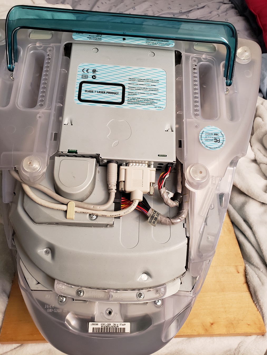
Above these is the power supply as well as some stickers giving model number mfg date and other information.

The plug is a standard 2-prong and is hard wired to the proprietary form factor power supply. All this together makes for a bad situation should the power supply die on you.

Removing the top cover of the case on the SE20 is not difficult at all but getting to the motherboard itself is a challenge.

Removing the case cover reveals that almost the entirety of the motherboard is covered by a metal shielding as well as the power supply and the drives. One of the few areas of the motherboard that is accessible is the dual 72 pin RAM slots for expanding the memory. specific details about memory for this model is basically nonexistent so my SE20 either has 1-2MB of RAM soldered directly onto the motherboard expandable to 10MB OR 6MB expandable to 64MB according to online sources. The 1994 manufacturing date on this model would suggest it’s probably a 6MB machine.

Below is the faceplate of the Towns SE20 which also holds the built-in speaker.

The floppy drives are connected to the motherboard via two separate floppy connectors located on the motherboard. Interestingly there are also two power connectors next to the floppy connectors. These power connectors act just like floppy Molex connectors but rather then coming off the PSU they connect via a small cable from the board to the floppy drive.

Behind the floppy drives lies the metal cage that supports any added expansion cards as well as the expansion card daughterboard.

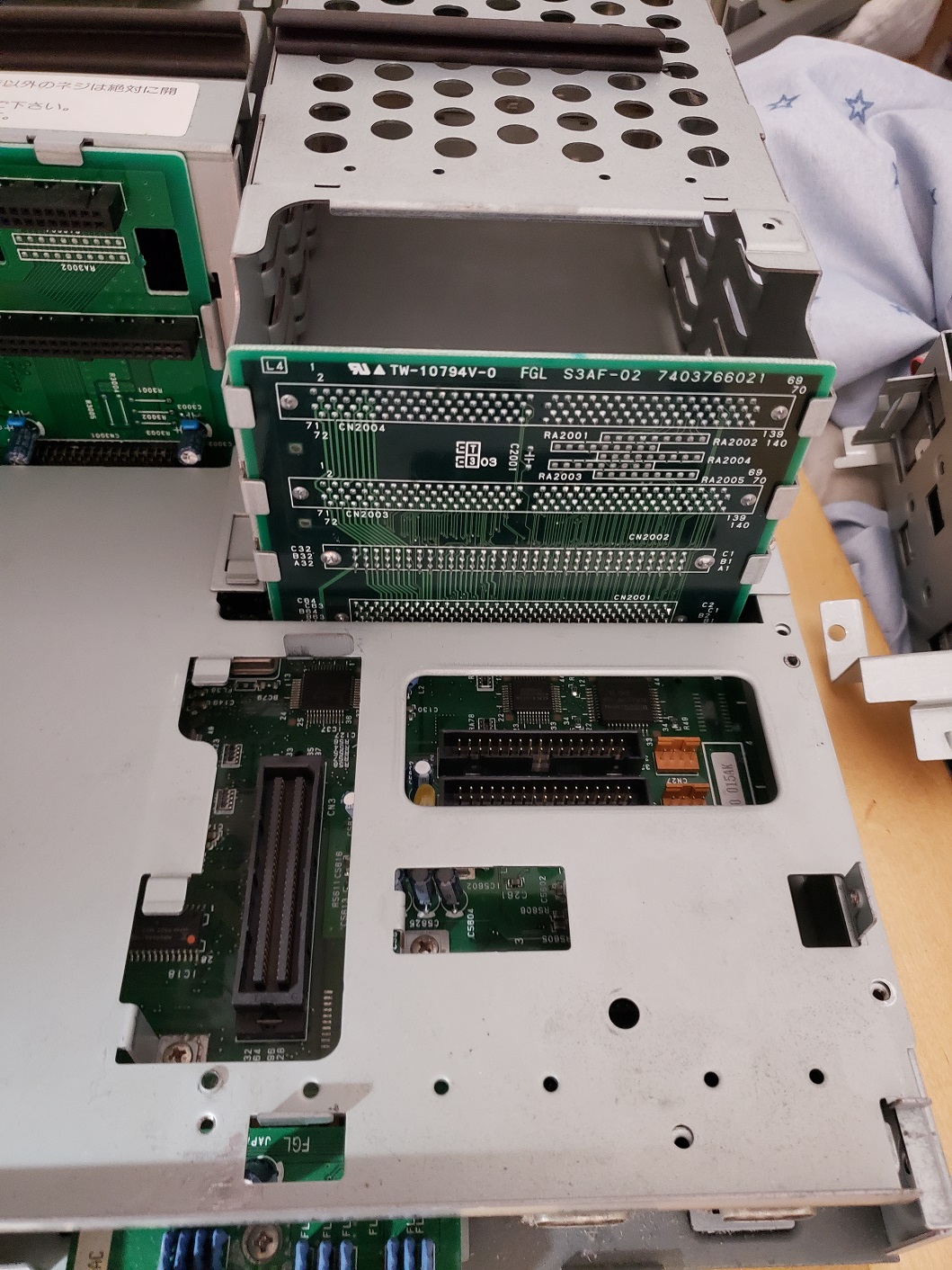
With the Floppy drives removed we can also see a slot for installing a CPU accelerator but we’ll talk about that shortly. First let’s take a look at the daughterboard located behind the floppy drives.

Here is the opposite side of the daughterboard. There are three proprietary looking connectors of types unknown to me. The bottom most looks like an Apple NuBus connector but I can’t confirm anything. Information on the FM Towns computers in the west is fairly scant when it comes to the fine details and the best I could find pertaining to these expansion slots was just a reference to the machine having three “bus slots”.

Now we move onto the what is both one of the FM Towns greatest strengths and definitely its greatest weakness, the CD-ROM drive.

The FM Towns line of computers was way ahead of other computers when it came to adopting the CD drive and had many exclusive CD enhanced versions of games when other PC systems were still using only Floppy drives. The operation of the FM Towns is more or less built around the CD drive, which leads us to the problem.

The drive itself is a Matsushita EBP504  x1 or x2 drive (information is sketchy). The CD drive interface and laser pick up are proprietary. This is understandable seeing as this was a very early attempt to add CD drives as standard to computes. The problem is two-fold. Firstly is that there was no third party alternatives or replacement drives made for the Towns proprietary interface which means if your CD drive dies and you can’t repair it then your pretty much out of luck.

This slideshow requires JavaScript.

The second big issue is that the majority of games expect to be run from this primary CD drive. You can add a hard drive or even an external SCSI CD drive as seen below via the rear SCSI connector but many games will still fail to load when attempting to boot via these alternative methods.

In short, if your primary CD drive dies in your FM Towns you have a severely compromised system which few options to fix the situation.

The CD drive connects via a daughterboard located in front of the power supply.

The lower connector is for the CD drive and although it looks like IDE it is NOT. As stated before the connection is a proprietary interface that as far as my research has found no one has made an adaptor to allow more common drives to work with nor were any other CD drives manufactured that used this interface. The CD drive is powered through this proprietary interface. The upper connector is a 50 pin SCSI connector intended for a hard drive although hard drives were not standard for the Towns as most programs were still meant to run from the CD drive. The interesting thing is that even though there is a spot to add a SCSI hard drive there is no molex connector coming off the power supply to power one.

The power supply is located behind the HDD/CD interface daughtercard and uses a connector with the motherboard I’ve never seen before. The form factor also seems to be proprietary.

With the various drives, bays and the power supply removed we get to the metal shield directly above the motherboard.

Removing the metal shield is a pretty straight forward process and just requires the removal of a few screws.

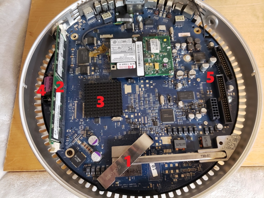
1) CPU – The CPU for the FM Towns SE20 is an Intel 486SX at 25MHz. This is a step up from earlier Towns computers that generally had 386 processors installed. The CPU is directly soldered to the motherboard but upgrading is possible via a CPU upgrade slot located next to the processor.

2) RAM – We already talked about memory but to go over it again. The Towns SE20 has two 72 pin slots for expanding the memory. My SE20 either has 1-2MB of RAM soldered directly onto the motherboard expandable to 10MB OR 6MB expandable to 64MB. The 1994 manufacturing date on this models would suggest it’s probably a 6MB machine though I only spot four memory chips suggesting it could be 2MB (512KB each, or 4MB (1MB each). Googling NEC 424800-70l seemed to indicate these are 512kx8 chips.

loading up MS-DOS 6.2 JPN version and running the mem command gives these details.

fmtextra1

After this I tried a variety of RAM modules and finally installed this 16MB module which on boot up created a RAM counter in the lower left hand corner of the screen which counted up to 18MB which would seem to confirm (16MB added + 2MB on-board).

fmymem2

I attempted to add a matching 16MB stick and recived an error on boot. counting up to 18MB would suggest online sources were wrong about 2MB motherboards being limited to 10MB maximum RAM.

3) CMOS battery – The battery thankfully is not the barrel type so it is not prone to leaking though it is not a standard CR2032 lithium coin battery and is a little bigger.

4) Power connector – The power supply connects to the motherboard by what I believe is another proprietary connection. You can see it in the image above for the RAM and the connection is obviously not AT or ATX. This can be an issue if you’re trying to replace the PSU.

5) Floppy connectors – As we saw earlier both of the floppy drives are connected via two separate floppy connectors on the motherboard itself along with two separate power jacks that will require two power cables.

6) CPU upgrade interface – This slot is for adding a “CPU upgrade card” which in effect disables the soldered on 25MHz 486SX and takes over control. The most popular card I’ve seen on sites like eBay replaces the on-board CPU with a 66MHz 486DX though other cards may exist.

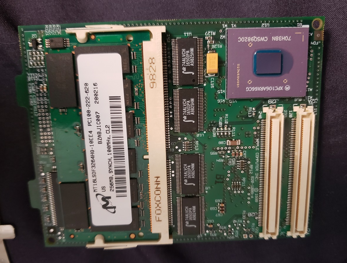
Below is an image of my 66MHz 486DX2 upgrade card.

The CPU is unfortunately soldered directly to the upgrade card though in theory you could simply desolder the current CPU and solder in a new one. One would have to be mindful of the voltage difference if you wanted to attempt a DX4 upgrade though since the DX2 operates at 5v while the DX4 is 3.3v so perhaps a 486 Overdrive chip with a voltage regulator would make a good upgrade candidate.

7) expansion card daughterboard interface – This is where the daughterboard that any expansion cards fit into interfaces with the motherboard.

8) CD and HDD interface – This is where the daughterboard for the CD drive and Hard drive interface with the motherboard.

A few final notes.

Games for the FMTowns are in general very expensive and almost all of them come exclusively on CDs. The primary CD drive should be able to read CD-R’s but as mine does not work at all I cannot confirm. Many games released for other PC’s but ported to the Towns line of computers are considered to be definitive versions usually since they were specifically enhanced for the Towns and the CD format. This along with a number of Towns exclusives make the Towns a desirable retro gaming PC. As I said most FM Towns games easily go for over $100 US dollar on sites like eBay though every once in awhile you may find a less desirable or incomplete game for cheaper. The sole FM Towns game I own is the port of Sim City seen below. Also keep in mind most Towns games require at least 2MBs of memory to be installed.

This slideshow requires JavaScript.

The Towns use its own OS called Towns OS and the upgraded Towns OS 2.1. Since a hard drive is not necessary for the FM Towns PC’s the OS is loaded via the CD drive. Windows 3,3.1 and 95 as well as DOS can be run on the FM Towns and Towns II. In order to boot from the CD drive there is a hidden C: drive contained in ROM with CD drivers. I was able to boot from the A: drive via a floppy before the machine eventually failed on me and I could not get the floppy drives to seek again.

The image above is a screen of a special version of DOS with SCSI drivers loaded in order to attempt to boot from the external SCSI drive though my efforts proved useless.

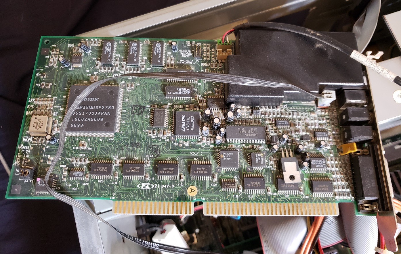
Audio – Besides being able to read and play Redbook CD audio @ 44.1KHz the towns is also capable of 6-channel stereo FM synthesis via a Yamaha chip as well as PCM sound via a sound chip from Ricoh. below is an image I took of the Yamaha chips as well as a chip from Ricoh that I believe is the PCM chip. The Ricoh chip is labeled RF5C190A while the Yamaha chips are labeled YMF276-M and YM3433B-F

Below are a number of photos I took of the motherboard. I can’t claim to understand what all these chips do but I assume these photos may prove helpful to those better versed on the technical side of things.

The FM Towns II SE20, as well as the rest of the FM Towns line of computers and including the consolized “Marty” to a lesser extent, are exotic and awesome retro computers. Unfortunately owning and collecting for one is a very frustrating and expensive pursuit. The computers themselves use so many proprietary components that if any one part fails it becomes extremely difficult to repair and/or replace. This is especially true for the CD drive which the entire computer is basically based around. Add in the further difficulties of having almost all the available information on the PC line is in Japanese and hardware and games are very expensive and you’re looking at a significant investment of money and time to maintain an FM Towns setup.

About two months ago I wrote an article on the Sun Ultra 10, a workstation from the late 1990s. This time we’re going to take a look at the first machine in the Sun Ultra line, the Sun Ultra 1 which launched in 1995.

Before we get into the article though I wanted to point out that I could not get this particular example to display and thus could not acquire some of the finer details or system specs. Also, as I’ve stated prior, I have very little experience with workstation type PC’s and thus will not be able to go into as much detail or specifics on various components. Please consider this article more of a simple overview and look into the internals of a Sun Ultra 1 case.

The Sun Ultra 1 uses a fairly compact desktop style case. Looking at the front you may be a little confused as to why there are no drives or maybe presume they are located under the holed grate which perhaps acts as a cover. Next to the Ultra 1 logo there is a green LED power light.

Turning the case to the side reveals that the drive bays are actually on the side of the computer. There is a floppy disk slot carved into the case of the computer intended for a standard 1.44MB floppy drive and a standard 5 1/4 drive bay on top generally occupied by a CD-ROM drive or a tape drive.

The keyboard for this PC is very similar to the one I have for the Sun Ultra 10 with a few differences, namely there is no individual LED lights on the top. Like the many Apple keyboards the Sun keyboard also has a connector on it for attaching a mouse. This keyboard is a little beat up with a cap missing but it feels like a fairly solid and heavy keyboard.

Here is the rear of the Ultra 1. Starting on the left we have two standard 3-pin power connectors, female and male, as well as a power switch that can be used to turn the Ulta 1 on and off. Moving to the right and ignoring the connector on top for now, the first port we come across is a parallel port and next to it is the keyboard/mouse port. The port above these built-in connectors is an expansion slot currently occupied by the video card.

To the right of the Keyboard/Mouse port is the AUI port or (Attachment Unit Interface), which according to the internet is apparently an interface between the network interface card and the ethernet cable. To the right of the AUI is the TPE (Twisted Pair Ethernet) Ethernet port. Above these ports are two serial ports labeled A and B.

Lastly to the right of the AUI and TPE ports is an external SCSI connector and four audio jacks. The four jacks from left to right are Headphones, Line Out, Line In and Microphone. Above these are two more slots for optional expansion cards.

Opening the case is a pretty easy process through the screws are interesting and have little springs on them. I’ve seen this before but not often on simple case screws.

Here is the Ultra 1 with the top of the case removed.

The upper right hand of the case has room for two hard drives. This example has two Seagate ST32155WC SCSI hard drives. These are server grade 2.1GB drives.

Now to look at the board itself and see if we can identify some parts.

1 ) CPU – The CPU area is covered by a plastic shield which I suppose acts as a sort of dust shield. Under the plastic is the CPU itself which is configured in a pretty common configuration for the time with a small black heatsink and small fan screwed on top. The CPU is a 64-bit Sun UltraSPARC processor, though since I haven’t removed the heatsink, boot to an OS or find a model tag I have no idea of the speed. Ultra 1’s came stock with CPU speeds of 143MHz, 167MHz and 200MHz, I suspect this example is the 143MHz model since the service ID tag has “140” within the ID which I’m guessing corresponds to the 143MHz model number.

The four screws that hold on the plastic shroud also hold the CPU fan to the heatsink. Also under the shroud are a number of tall back chip heatsinks that seem to be working to cool a number of chips located around the CPU. I’m guessing these chips are the 512KB of L2 cache for the CPU but I am unsure. On my Ultra 1, three of these heatsinks were extremely loose, one falling completely off the chip, and required some new thermal adhesive.

2 ) RAM – The Ultra 1 can accept up to a whopping 1GB of 60ns ECC RAM via eight slots. From my understanding the RAM is somewhat non-standard and is about the tallest I’ve ever seen RAM be. The RAM must be installed in pairs and the memory slots do use a special lever on the sides to secure and release the individual RAM modules.

3 ) The Ultra 1 has three SBus slots. These are Suns high-speed bus slots for connecting things like the video card. This model has three SBus connectors but some “E” models only had two SBus slots with an additional UPA slot (Ultra Port Architecture) for high bandwidth video cards.

The Ultra 1 unlike the later Ultra 10 does not have built-in video capabilities. The most common video card that seems to of come installed with the Ultra 1 is this card below from LSI. This card, like most Sun workstation video cards, uses a DB13W3 video connector so you will need a Sun DB13W3 to standard VGA connector adaptor. Make sure the adaptor is wired for Sun computers since Silicon Graphics workstations use the same style connector but are wired different.

This video card interfaces via one of the three SBus connectors on the motherboard.

I do not know the specifics of this card but it is a little odd as I’ve never seen a video card with LSI chips before this one. Also on the card are the names of various individuals, presumably the designers, but two of these names are crossed out. Was there some kind of falling out on the design team?

4 ) The board itself is covered in various proprietary chips that I couldn’t begin to tell you what they do.

This slideshow requires JavaScript.

5 ) SCSI cable & connector.

6 ) Battery – Much like the Dallas RTC the battery on the Ultra 1 is enclosed in a hard plastic shell. Thankfully the battery is socketed and can be removed and replaced or even modified like a Dallas RTC to use a Lithium coin battery.

7 ) Sound – Sound on the Ultra 1 is provided by a Crystal CS4231A-KQ chip.

And that’s about the extent of my journey with the Sun Ultra 1. I could not get the machine to display on any monitor. I’m unsure if my issue was my DB13W3 to standard VGA adaptor for the video output or a more serious issue with the video card or board itself. Doing a bootup diagnostic test via holding the STOP key and the D key I did not get any kind of error codes so I’m at a loss. The Ultra 1 was said to be one of the workstations used to produce the hit movie Toy Story so it is quite a capable 90s workstation and graphic design PC but for gaming, obviously, look elsewhere.

Way back in Jan of 2016 I wrote an article on the slot loading iMac G3. This time we’re going to take a look at the original Bondi blue “tray loading” iMac G3 and see how this iconic computer that is often times referred to as “the Mac that saved Apple” compares to its later “slot loading” revision. In this article we will be looking at a more or less bone stock very first revision or revision A model originally released in August of 1998.

As I stated in my original post on the slot loading variant of the iMac I was not the greatest fan of the Mac and was firmly in the Wintel PC camp during that time. My disdain for the iMac though was at the height of my displeasure with all things Apple and I honestly did not know why anyone would want one of those computers. Time and experience though has softened my stance and I now can appreciate these computers for what they are and the use they were intended for. The all in one iMac G3 was not a new idea but it was an idea that Apple as a company had moved away from during the latter half of the ’90s to make more generic “PC” type machines and hence lost a lot of what made Apple unique and stand out in the market. The iMac G3 was an all-in-one machine and was extremely simple to set up and played with Apple’s strength of focusing on industrial design with a colorful and inviting Bondi blue colored shell as opposed to the standardized beige of almost all other PC cases. The iMac was intended to be extremely user-friendly and be simple to set up like a microwave or a toaster. This computer was aimed at the average user just wanting to “surf the net” or write school assignments rather than power users or gamers (even though the iMac certainly could be gamed on).

The original model seen here only came in Bondi blue as opposed to later models that were offered in a variety of colored shells. A handle was provided at the top to help move the Mac around but to be honest it always feels a little awkward to use and I always feel like it’s going to snap off despite the handle being very sturdy.

The bulk of the iMac is taken up by the built-in 15-inch shadow mask CRT monitor capable of resolutions up to 1024 x 768. The iMac G3’s kept this same spec monitor throughout all models though later slot loading iMac’s supplied an external VGA port to connect to an external monitor. These early tray loaders did not which makes it quite unfortunate if your monitor dies. The rear of the Mac hides only a small handle, which is used when removing the motherboard, and a standard 3-prong power connector.

They also came with a matching Bondi blue iMac keyboard and mouse. The keyboard is a simple Apple USB keyboard and is not so dissimilar from others besides the color but the mouse, a USB ball type mouse, is the infamous “puck mouse” so called because of its hockey puck like shape.

Unfortunately the rumors of the poor ergonomics of the of the puck mouse are completely true and the mouse can be very awkward and uncomfortable to use over any extended period of time. This isn’t a major problem since the mouse can be swapped out with any Apple USB mouse including later Apple Pro mice which use a standard shape and sports a laser as opposed to the older ball for tracking. The puck mouse also uses the traditional one-button Apple style mouse so no scroll wheel. The mouse has held up well though I’m not sure if this is from rugged construction or lack of use.

The iMac was famously the first Mac to drop the floppy drive although one was easily added via a USB port. In its place a 24x CD-ROM drive was standard and is located below the monitor. The early runs of the iMac used a tray loading CD drive, hence the “tray loader” title where as the later models used a self-loading slot mechanism. Next to the CD drive we have a power button that emits a soft green light when on and on the right and left sides we have two built-in stereo speakers. These speakers do have a habit of rotting a bit but it is a repairable issue and fortunately this particular iMac does not suffer from the foam around the speakers deteriorating.

The speaker on the left has a wireless 4Mbits/s IrDA inferred sensor which was removed starting with the revision C tray loaders. The right speaker has dual 1/8 stereo jacks for hooking up headphones that two users can use at once which is quite nice. Underneath the Mac is a fold-out stand of the same Bondi blue as the case.

On the left side of the iMac we have a small compartment housing some various ports. The is a plastic cover which can either be removed entirely or replaced after your various peripherals are plugged in and the wires snaked out through the several openings provided.

Once the plastic cover is removed we are greeted by a variety of ports.

On the left we have two more audio jacks, one for a microphone and a second for optional external speakers, handy if the built-in speakers fail or are not powerful enough for your liking. Next to that is a scant two USB 1.1 ports. The iMac is also known for going all in on USB and ditching the traditional Apple ADB ports in favor of USB though I wish more USB ports were made available. The mouse is generally expected to plug into the USB port on the keyboard (this why the cord is generally so short) and this does help free things up. A USB hub can also be used without issue in case you have multiple USB devices you want to use. Next we have a 10/100 Ethernet jack and lastly a 56k Modem jack.

Under these ports we have a mysterious little covered cutout held in by two screws. Behind this cover is what is commonly called a “mezzanine slot”. This is a sort of expansion slot that originally was only supposed to be for Apple’s internal use but you can use it for other things and third parties did make expansion devices that took advantage of the presence of this slot though from my research they seem to be extremely rare. I even know of at least one third party adaptor that uses the slot to add a 3DFX Voodoo II upgrade and according to Wikipedia SCSI and TV tuner cards were also available though I’ve never seen any of these cards in person. This port was removed along with the previously mentioned inferred sensor with the tray loading revision C model.

Opening the iMac is much easier then it is on later revisions and there is no “mesh” layer present that requires removal. You just need to remove a few screws on the underside and then use the handle to pull off the plastic case section. Once the outer case is removed as well as a few more screws and cables the motherboard assembly will slide out though be careful as with most older Macintosh computers the plastic casing can be delicate and things tend to snap off.

Here is the underside of the case with the motherboard assembly removed. The early tray loaders sport a fan for cooling as seen here while the later slot loaders used a fanless convection process to cool internals.

Here we have the tray that holds the motherboard and most of the iMac’s components completely removed from the case. The hard drive is located under the CD-ROM drive as seen in the image below. Mine came with the original 4GB 5400 RPM drive.

imactlx1

Originally the iMac came preloaded with Mac OS 8.1 or 8.5 with the ability to officially upgrade to OS X 10.3.9 though mine has been upgraded to OS 9.2.2.

1 ) CPU/RAM – The CPU and RAM on the tray loaders were both located on daughterboards that connected directly to the main motherboard. The metal cage enclosing the daughterboard easily wiggles off with some light force. Revision A as seen in this article and revision B iMacs only shipped with a 233MHz PowerPC 750 G3 processor w/ 512kb of L2 cache but later revision C and D tray loader iMacs had 266MHz and 333MHz CPUs installed.

tlmac12

imactlx3

imactlx4

CPU module top

imactlx5

CPU module bottom

Standard RAM amount was 32MB of PC100 SDRAM in a smaller laptop style form factor. The revision A iMac was expandable officially to 128MB and unofficially to 384MB. Revision B, C and D were officially expandable to 256MB and unofficially to 512MB. My machine came with the oddly numbered 288MB of RAM installed. It seems the previous owner did make the sole upgrade of adding a 256MB stick of memory in addition to the 32MB of RAM already installed.

I had no problem up upgrading my RAM to a full 512MB by installing two 256MB RAM modules despite being a Rev. A motherboard and sources online indicating 384MB being the limit.

2) Video – Original revision A iMacs shipped with a built-in Rage IIc chip and 2MB of SGRAM as seen on my iMac but this was quickly changed in revision B and up tray loaders to the much more powerful Rage Pro chipset with 6MB of SGRAM standard. The original revision A boards can be upgraded to a full 6MB of SGRAM.

The ATI chip isn’t a surprise as Apple has a history of using ATI chips for graphics in this era. As far as I can tell the revision A iMac G3 is the sole computer to use this specific version of the Rage chip built in. Overall the Rage IIc is an adequate chip, though by 1998 it was getting quite outdated and was seen as a entry level 3D video chip. 2D applications should run just fine as well as less intensive 3D titles as long as resolutions and features are kept in check.

imactlx2

with 4MB extra video RAM module

3) Sound – Sound has always seemed like a bit of an afterthought in Apple machines and finding specifics has always been a bit of a chore as sound chips aren’t commonly noted on spec sheets. The iMac would appear to use Crystal CS4211-KM chip which supports simulated surround sound via the two built-in speakers.

4) Battery – Lastly we have the PRAM battery which acts just like the CMOS battery in a standard motherboard. Be sure to replace this on any newly acquired Macintosh computer.

Accessories

Compucable iDock II

The iDock is an interesting accessory that was designed for the iMac to extend its capabilities. My version is the iDock II which features a built-in 1.44MB floppy drive. As far as I can tell the floppy drive is the only difference between the iDock I and II. The iDock connects to the iMac by way of a standard USB cable and requires its own power supply.

20220712_185418

The top of the iDock swivels allowing you some measure of turning your iMac which sits on top of the iDock.

20220712_185413

The rear of the iDock features several ports to expand your iMac such as four USB ports, two Geo ports and one ADB port. The ADB port has been reported to not work or only partially work on these units. On mine I was able to get an ADB mouse to work but it was very iffy and the response was poor. The iDock does require special drivers to function.

20220712_185433

The iMac does what it set out to achieve and I can see now what I couldn’t see as my high school self, why the iMac succeeded. It wasn’t meant for people like me. It was meant less for hardcore PC gamers and those that liked to expand and tinker with their computers and more for the everyday user, the soccer mom, the person that just wanted to do homework and surf the internet and it made a pretty easy to setup and usable computer to sit in the corner of the family room and have for general family usage.

As a collectors piece the Bondi blue iMac is certainly worth adding to the collection and holds a significant place in computer history and especially Apple’s history. They are still relatively inexpensive as of 2019 though an original revision A may take some work track down and identify. If your purely looking for a Macintosh for late 90’s gaming though there are much better options. Personally, I think your better off acquiring a Power Macintosh G3 tower or desktop simply for the vastly greater options you get in upgrading (such as PCI slots) and higher ease of repair. Failing finding one of these a later slot loading iMac or even a G4 could make a good choice as they seem to be easier to source and are more powerful out of the box.

This slideshow requires JavaScript.

FDISKformat

A place for the pc collector

I ❤ Old Games!

Probabilmente il miglior blog bilingue al mondo*

Waltorious Writes About Games

Game-related ramblings.

NekoJonez's Gaming Blog

My Gaming Timeline

Evelynn Star

Lynn talks about video games, records and books ...

Retro Megabit

Sharing My Retro Video Game Collection.

133MHz's Junk Box

Random electronics and gaming crap

SNES A Day

Chronogaming project featuring reviews, screenshots, and videos of the entire Super Nintendo library in release order.

Retrocosm's Vintage Computing, Tech & Scale RC Blog

Random mutterings on retro computing, music, plus radio controlled scale modelling.

The PewPew Diaries.

Work(s) in Progress!

1001Up

1001 video games and beyond

retro computing and gaming plus a little more

sparcie

retro computers and stuff

jispylicious

Stay Jispy!