PasM24 / Pas M24W IP1646
PasM24 / Pas M24W IP1646
PasM24 / Pas M24W IP1646

You also want an ePaper? Increase the reach of your titles
YUMPU automatically turns print PDFs into web optimized ePapers that Google loves.
<strong><strong>Pas</strong>M24</strong> / <strong>Pas</strong> <strong>M24W</strong><br />
<strong>IP1646</strong><br />
rev. 2004-09-02<br />
I GB F D E P<br />
Manuale di<br />
installazione per<br />
radar a microonde<br />
Installation manual<br />
for microwave<br />
sensor<br />
Manuel<br />
d’installation pour<br />
radars à microondes<br />
Installationsanleitung Manual de<br />
für Mikrowellen- instalaciòn para<br />
Bewegungsmelder radar de<br />
microondas<br />
Manual de instalação<br />
para radar a microondas<br />
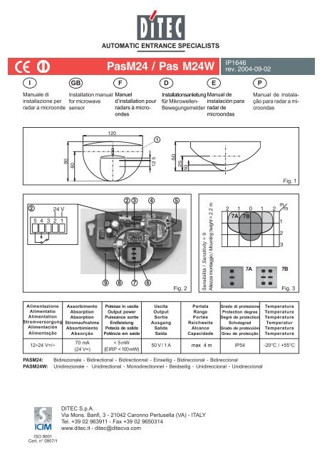
120<br />
1<br />
80<br />
60<br />
12 5<br />
25<br />
10<br />
50<br />
Fig. 1<br />
2<br />
5<br />
4<br />
3<br />
24 V<br />
2<br />
1<br />
9<br />
2 3 4 5<br />
8 7 6<br />
Sensibilità / Sensitivity = 9<br />
Altezza montaggio / Mounting height = 2.2 m<br />
2 1 0 1 2<br />
7A 7B<br />
7A<br />
m m<br />
7B<br />
Fig. 2 Fig. 3<br />
1<br />
2<br />
3<br />
Alimentazione<br />
Alimentatio<br />
Alimentation<br />
Stromversorgung<br />
Alimentaciòn<br />
Alimentação<br />
Assorbimento<br />
Absorption<br />
Absorption<br />
Stromaufnahme<br />
Absorbimiento<br />
Absorção<br />
Potenza in uscita<br />
Output power<br />
Puissance sortie<br />
Endleistung<br />
Potecia de salida<br />
Potência em saída<br />
Uscita<br />
Output<br />
Sortie<br />
Ausgang<br />
Salida<br />
Saída<br />
Portata<br />
Range<br />
Portée<br />
Reichweite<br />
Alcance<br />
Capacidade<br />
Grado di protezione<br />
Protection degree<br />
Degré de protection<br />
Schutzgrad<br />
Grado de protecciòn<br />
Grau de protecção<br />
Temperatura<br />
Temperature<br />
Température<br />
Temperatur<br />
Temperatura<br />
Temperatura<br />
12÷24 V=/~<br />
70 mA<br />
(24 V=)<br />
< 5 mW<br />
(EIRP < 100 mW)<br />
50 V / 1 A max 4 m<br />
IP54<br />
-20°C / +55°C<br />
PASM24:<br />
PAS<strong>M24W</strong>:<br />
Bidirezionale - Bidirectional - Bidirectionnel - Einseitig - Bidireccional - Bidireccional<br />
Unidirezionale - Unidirectional - Monodirectionnel - Beidseitig - Unidireccional - Unidireccional<br />
DITEC S.p.A.<br />
Via Mons. Banfi, 3 - 21042 Caronno Pertusella (VA) - ITALY<br />
Tel. +39 02 963911 - Fax +39 02 9650314<br />
www.ditec.it - ditec@ditecva.com
ANTENNA = 7A<br />
Sensibilità / Sensitivity = 9<br />
2.2 m<br />
AVVERTENZE GENERALI PER LA SICUREZZA<br />
Il presente manuale di installazione è rivolto esclusivamente a<br />
personale professionalmente competente. Leggere attentamente<br />
le istruzioni prima di iniziare l’installazione del prodotto. I materiali<br />
dell’imballaggio (plastica, polistirolo, ecc.) non vanno dispersi nell’ambiente<br />
e non devono essere lasciati alla portata dei bambini in quanto<br />
potenziali fonti di pericolo. Prima di iniziare l’installazione verificare<br />
l’integrità del prodotto. Per l’eventuale riparazione o sostituzione dei<br />
prodotti dovranno essere utilizzati esclusivamente ricambi originali.<br />
I<br />
ANTENNA = 7A<br />
Sensibilità / Sensitivity = 9<br />
2.2 m<br />
30˚<br />
45˚<br />
2 1 0 1 2<br />
2 1 0 1 2<br />
0˚<br />
15˚<br />
30˚ 20˚<br />
45˚<br />
45˚<br />
m m<br />
1<br />
2<br />
3<br />
Fig. 4<br />
m m<br />
1<br />
2<br />
3<br />
1. INSTALLAZIONE<br />
Fissare il radar in modo stabile ad una altezza non superiore a 4 m e in<br />
modo tale da rilevare tutta l’area di fronte al vano passaggio. Evitare di<br />
collocare degli oggetti che possono oscillare o vibrare nell’area di<br />
rilevamento come tende, cartelli o piante. Assicurarsi che non ci siano<br />
luci fluorescenti nell’area di rilevamento.<br />
1.1 Incollare l’etichetta in dotazione nel punto dove intendete fissare<br />
il radar.<br />
1.2 Forare come indicato nell’etichetta.<br />
1.3 Inserire le viti in dotazione, senza avvitarle completamente.<br />
1.4 Prevedere l’uscita cavi [9], accertandosi di lasciare abbastanza<br />
cavo per il collegamento alla morsettiera [2] e [4].<br />
1.5 Togliere il coperchio [1], fissare la base a parete e avvitare<br />
completamente le viti.<br />
N.B. Per installazioni a soffito, la parte sferica del radar deve essere<br />
posizionata frontalmente e opposta rispetto alla porta (fig. 4). E’<br />
possibile utilizzare il supporto ad incastro (<strong><strong>Pas</strong>M24</strong>I) per installazioni<br />
a soffitto e il cappello di protezione (<strong><strong>Pas</strong>M24</strong>C) per una migliore<br />
protezione all’acqua.<br />
ANTENNA = 7A<br />
Sensibilità / Sensitivity = 0, 3, 6, 8, 9.<br />
2.2 m<br />
30˚<br />
2 1 0 1 2<br />
0<br />
3<br />
6<br />
9<br />
Fig. 5<br />
m m<br />
REGOLAZIONE LATERALE / LATERAL ADJUSTMENT<br />
ANTENNA = 7A<br />
Sensibilità / Sensitivity = 1 , 6, 9.<br />
Altezza montaggio / Mounting height = 2.2 m<br />
1<br />
2<br />
3<br />
Fig. 6<br />
2. COLLEGAMENTI ELETTRICI<br />
Effettuare i collegamenti alla morsettiera [2] usando il cablaggio in<br />
dotazione (lunghezza 2.5 m) come indicato in fig. 2.<br />
3. REGOLAZIONE AREA DI RILEVAMENTO<br />
3.1 L’area di rilevamento è determinata dalla scelta dell’antenna<br />
planare [7]: per ottenere un’area di rilevamento ampia usare<br />
l’antenna a 3 elementi [7A]; per un’area di rilevamento più stretta<br />
usare l’antenna a 6 elementi [7B] (fig. 3).<br />
Per sostituire l’antenna a 3 elementi con quella a 6 in dotazione<br />
(posta sotto il circuito stampato), rimuovere il coperchio di<br />
protezione, cambiare l’antenna e rimettere il coperchio di<br />
protezione.<br />
3.2 E’ possibile modificare l’area di rilevamento variando 3 parametri:<br />
- l’angolazione verticale dell’antenna [8] come indicato nelle figure<br />
5 e 6;<br />
- la sensibilità di rilevazione mediante la pressione dei tasti +/- [5]<br />
da 0 a 9, ogni pressione equivale ad un aumento o una<br />
diminuzione pari ad una unità, come indicato in figura 6 (sensibilità<br />
di default = 7);<br />
- l’altezza di installazione del radar (max. 4 m).<br />
3.3 La posizione laterale dell’area di rilevamento è determinata dalla<br />
rotazione laterale dell’antenna [6], come indicato in fig. 7.<br />
-30˚ +30˚<br />
0˚<br />
2 1 0 1 2<br />
1 1<br />
3 3<br />
6 6<br />
9 9<br />
-30˚ +30˚<br />
m m<br />
1<br />
2<br />
3<br />
Fig. 7<br />
4. REGOLAZIONE CON TELECOMANDO Tel2<br />
I parametri del radar possono essere modificati mediante il telecomando<br />
Tel2 (consultare il relativo manuale).<br />
Questi parametri di default possono essere ripristinati premendo contemporaneamente<br />
i pulsanti +/- [5] per 2 s.<br />
Solo per <strong><strong>Pas</strong>M24</strong>. Il telecomando Tel2 consente la regolazione dei<br />
parametri del QE 94 collegando il connettore [4] al TelRS mediante<br />
l’apposito cablaggio in dotazione (lunghezza 2 m).<br />
5. SEGNALAZIONI<br />
Il LED [3] lampeggia un paio di secondi quando il radar è attivato e<br />
lampeggia continuamente durante le regolazioni da Tel2.<br />
Il LED [3] si accende quando il sensore rileva movimento.<br />
DITEC S.P.A - <strong>IP1646</strong> - PAS M24/<strong>M24W</strong><br />
2
GB<br />
GENERAL SAFETY PRECAUTIONS<br />
This installation manual is intended for professionally competent<br />
personnel only. Read the instructions carefully before beginning<br />
to install the product.<br />
Packaging materials (plastic, polystyrene, etc.) must not be allowed to<br />
litter the environment and must be kept out of the reach of children for<br />
whom they may be a source of danger.<br />
Before beginning the installation check that the product is in perfect<br />
condition. For repairs or replacements of product only original spare<br />
parts must be used.<br />
CONSIGNES GENERALES DE SECURITE<br />
Cette notice d’installation est destinée exclusivement aux<br />
professionels qualifiés.<br />
Lire attentivement les instructions avant de procéder à l’installation du<br />
produit.<br />
Les materiaux de l’emballage (plastique, polystyréne, etc ne doivent<br />
pas être abandonnés dand la nature et ne doivent pas être laissés à<br />
la portée des enfants, car ils sont une source potentielle de danger. En<br />
cas de réparation ou de remplacement des produits, sed piéces de<br />
rechange originales impérativement être utilisées.<br />
F<br />
1. INSTALLATION<br />
Firmly secure the radar at a height of no more than 4 m, installing it so<br />
that it can properly scan the entire area in front of the passageway.<br />
Never place in the detection area any objects which may move such<br />
as shades, signs or plants. No fluorescent lighting in sensing field<br />
must be.<br />
1.1 <strong>Pas</strong>te the label provided on the point in which you have decided<br />
to secure the radar.<br />
1.2 Drill as instructed.<br />
1.3 Insert screws supplied but not screw them fully home.<br />
1.4 Provide a cable output [9] making sure you have enough extra<br />
cable for the connection to terminal strips [2] and [4].<br />
1.5 Remove cover [1], fix the base on the wall and tighten the screw.<br />
NOTE: As far as ceiling installations are concerned, the spheric part<br />
of the radar should be located on the front, side opposite the door (fig.<br />
4). It is possible to use the embedding support (<strong><strong>Pas</strong>M24</strong>I) for a ceiling<br />
mounting and the protection cap (<strong><strong>Pas</strong>M24</strong>C) for a better water<br />
tightness.<br />
2. ELECTRICAL CONNECTION<br />
Make the connections to the terminal strip [2] using the wiring provided<br />
(length 2.5 m) as shown in fig. 2.<br />
3. SENSING FIELD ADJUSTMENT<br />
3.1 The sensing field is determined by the choise of the planar<br />
antenna [7]: to obtain a wide sensing field use the 3-elements<br />
antenna [7A]; for a narrow sensing field use the 6-elements<br />
antenna [7B] (fig. 3).<br />
In order to replace the 3-element antenna with the 6-element<br />
antenna provided (located beneath the printed circuit), remove<br />
the protective cover of the antenna, change the antenna and<br />
replace the protective cover.<br />
3.2 Change the following 3 parameters for modifying the detection<br />
area:<br />
- the vertical tilt angle of the antenna [8] as shown in figs 5 and 6;<br />
- detection sensitivity by pressing keys +/- [5] from 0 to 9. Every<br />
time the key is pressed, the value increases or decreases by<br />
one digit as shown in figure 6 (default sensitivity = 7);<br />
- the sensor mounting height (max. 4 m).<br />
3.3 The lateral position of the sensing field is determined by the<br />
lateral rotation of antenna [6], as shown in fig. 7.<br />
4. ADJUSTMENT WITH TEL2 REMOTE CONTROL<br />
The radar parameters can be modified by means of the Tel2 remote<br />
control (refer to the corresponding manual).<br />
These default values may be restored pressing together the push<br />
buttons +/- [5] for at least 2 s.<br />
Only for <strong><strong>Pas</strong>M24</strong>. The Tel2 remote control allows the setting of the QE<br />
94 parameters by connecting the connector [4] to the TelRS by means<br />
of the specific wiring provided (length 2 m).<br />
5. SIGNALING<br />
The LED [3] flashes for a fews seconds when the sensor is started<br />
up, and flashes continuosly during Tel2 configuration.<br />
The LED [3] lights up when the sensor detects motion.<br />
1. INSTALLATION<br />
Fixer le radar de façon stable à une hauteur maximale de 4 m, de telle<br />
sorte qu’il détecte toute la zone située en face de l’ouverture de passage.<br />
Eviter de placer des objets qui peuvent osciller dans la zone de<br />
détection, tels que, par exemple, des rideaux, des panneaux ou des<br />
plantes. Le détecteur ne doit pas avoir de tube néon dans lobe de<br />
détection.<br />
1.1 Coller l’étiquette fournie avec le radar sur le point où l’on souhaite<br />
fixer le radar.<br />
1.2 Forer selon les indications sur le gabarit.<br />
1.3 Engager les vis, ne pas visser à fond.<br />
1.4 Prévoir la sortie pour les câbles [9], en veillant à laisser assez<br />
de câble pour la connexion au bornier [2] et [4].<br />
1.5 Enlever le couvercle [1], placer l’embase au mur et serrer les vis.<br />
Nota. Pour les installations au plafond, la partie sphérique du radar<br />
doit être en position frontale et opposée par rapport à la porte (fig. 4).<br />
Il est possible de utiliser le support d’encastrement (<strong><strong>Pas</strong>M24</strong>I) pour<br />
montage encastré au plafond et le capot de protection (<strong><strong>Pas</strong>M24</strong>C)<br />
pour une meilleure protection contre la pluie.<br />
2. RACCORDEMENTS ELECTRIQUES<br />
Effectuer les connexions au bornier [2] en utilisant le câblage fourni<br />
(longueur 2,5 m) de la façon indiquée à la figure 2.<br />
3. REGLAGES DU LOBE DE DETECTION<br />
3.1 La largeur du lobe est déterminée par le choix de l’antenne<br />
planaire [7]: pour obtenir un lobe large utiliser l’antenne à 3<br />
éléments [7A]; pour un lobe étroit utiliser l’antenne à 6 éléments<br />
[7B] (fig. 3).<br />
Pour remplacer l’antenne à 3 éléments par celle à 6 fournie avec<br />
le radar (placée sous le circuit imprimé), elever la protection de<br />
l’antenne, changer l’antenne et remettre la protection de l’antenne.<br />
3.2 Il est possible de modifier la zone de détection, en modifiant 3<br />
paramètres:<br />
- la position angulaire verticale de l’antenne [8] de la façon indiquée<br />
à la figure 5 et 6;<br />
- la sensibilité de détection peut être variée au moyen de la pression<br />
des touches +/- [5] de 0 à 9. Chaque pression équivaut à une<br />
augmentation ou à une diminution d’une unité, tel qu’il est indiqué<br />
à la figure 6 (sensibilité par défaut = 7);<br />
- la hauteur de montage du détecteur (max. 4 m).<br />
3.3 La position latérale du lobe est determinée par la rotation latérale<br />
de l’antenne [6], de la façon indiquée à la figure 7.<br />
4. REGLAGES AVEC TELECOMMANDE TEL2<br />
Les paramètres du radar peuvent être modifiés au moyen de la<br />
télécommande Tel2 (voir le manuel correspondant).<br />
Ou peut retrouver ces valeurs par défault en paussant simultanément<br />
les deux boutons poussoirs +/- [5] pendant au moins 2 s.<br />
Soulement pour <strong><strong>Pas</strong>M24</strong>. La télécommande Tel2 permet le réglage<br />
des paramètres du QE 94 en reliant le connecteur [4] au TelRS au<br />
moyen du câblage fourni prévu à cet effet (longueur 2 m).<br />
5. SIGNALISATION<br />
La LED [3] clognote pendant qualques secondes lors de la mise en<br />
serive et elle clignote en permanence lors de la reglage avec Tel2.<br />
La LED [3] s’allume quand le détecteur détecte.<br />
3 DITEC S.P.A - <strong>IP1646</strong> - PAS M24/<strong>M24W</strong>
D<br />
ALLGEMEINE SICHERHEITSHINWEISE<br />
Das vorliegende Installationshandbuch ist ausschliesslich für<br />
Fachpersonal bestimmt. Vor Einbaubeginn sind die Anweisungen<br />
sorgfältig durchzulese.<br />
Das Verpackunsmaterial (Kunststoff, Polystyrol, usw.) ist vorschriftsmäßig<br />
zu entsorgen.<br />
Es ist von Kindern fernzuhalten, da es eine Gefahr für sie bedeutet.<br />
Vor Beginn der Montage ist der einwandfreie Zustand des Produkts zu<br />
überprüfen. Bei Reparatur und Austausch sind ausschliesslich<br />
Originalersatzteile zu verwenden.<br />
1. MONTAGE<br />
Das Radargerät in einer Höhe von max. 4 m befestigen, so dass es<br />
den gesamten Bereich vor dem Durchgang erfasst. Es dürfen keine<br />
Gegenstände so positioniert werden, dass sie durch Bewegung in<br />
den Erfassungsbereich hineinreichen können, wie z.B. Gardinen,<br />
Schilder oder Pflanzen. Es darf sich keine Neonröhre im Erfassungsfeld<br />
des Sensors befinden.<br />
1.1 Das mitgelieferte Etikett an der Stelle aufkleben, an der das<br />
Radarsystem befestigt werden soll.<br />
1.2 Gemäß den Angaben in der Schablone bohren<br />
1.3 Die Schrauben anlegen, nicht ganz festschrauben.<br />
1.4 Kabelausgang [9] vorsehen, wobei sicherzustellen ist, daß das<br />
Kabel lang genug ist, um mit der Klemme [2] und [4] verbunden<br />
zu werden.<br />
1.5 Nehmen Sie den Deckel ab [1]. Befestigen Sie die Platte an der<br />
Wand und die Schrauben festschrauben.<br />
N.B. Bei Deckeninstallationen muß der runde Teil des Radar-<br />
Bewegungsmelders genau vor die Tür und auf die der Tür<br />
gegenüberliegende Seite gesetzt werden (Abb. 4).<br />
Für den Deckeneinbau benötigen Sie das dafügeeignete<br />
Einbauzubehör (<strong><strong>Pas</strong>M24</strong>I). Für eine wirksameren Schutz gegen Regen<br />
ist das Watterdach bestimmt (<strong><strong>Pas</strong>M24</strong>C).<br />
2. ELEKTRISCHE ANSCHLUSSE<br />
Die mitgelieferten Kabel (Länge 2,5 m) wie in Abb. 2 an die Klemmen [2]<br />
anschließen.<br />
3. EINSTELLUNG DES ERFASSUNGSFELD<br />
3.1 Der Erfassungsfeld wird durch die Wahl der Planarantenne<br />
bestimmt [7]: um eine breites Feld zu erhalten, die Antenne mit<br />
den 3 Elementen [7A] gebrauchen; um eine schmales Feld zu<br />
erhalten, die Antenne mit den 6 Elementen [7B] gebrauchen<br />
(Abb. 3).<br />
Um die dreiteilige Antenne durch die mitgelieferte sechsteilige<br />
Antenne zu ersetzen (die unter der gedruckten Schaltung<br />
angeordnet wird), nehmen Sie vorsichtig den Schutz von der<br />
Antenne ab, wechseln Sie die Antenne und bringen Sie den<br />
Antenneschutz wieder an.<br />
3.2 Es ist möglich, den Erfassungsbereich zu ändern, indem drei<br />
Parameter geändert werden:<br />
- die Senkrechte Winkelposition der Antenne [8] wie in Abb. 5 und<br />
6 angezeigt;<br />
- die Empfindlichkeit durch Druck der Tasten +/- [5] von 0 bis 9,<br />
wobei jeder Tastendruck einer Erhöhung oder Reduzierung um<br />
eine Einheit erhöht, wie in Abb. 6 dargestellt<br />
(Standardempfindlichkeit = 7);<br />
- die Empfindlichkeit des Sensors (max. 4 m).<br />
3.3 Die Seitliche position des Erfassungsfeldes wird durch die<br />
Seitliche Drehung der Antenne bestimmt [6], wie in Abb. 7<br />
angezeigt ;<br />
4. EINSTELLUNG MIT FERNSTEUERUNG TEL2<br />
Die Radarparameter können mit Hilfe der Fernsteuerung Tel2 geändert<br />
werden (siehe entsprechendes Handbuch).<br />
Man kann diese Richtwerte wiederfinden, indem man zu gleicher Zeit<br />
mindestens 2 s lang auf die beiden Drucktasten +/- [5] drückt.<br />
Nur für <strong><strong>Pas</strong>M24</strong>. Die Fernsteuerung Tel2 ermöglicht die Einstellung<br />
der Parameter der Steuerung 94, indem der Stecker [4] über das<br />
mitgelieferte Kabel (Länge 2 m) mit TelRS verbunden wird.<br />
ADVERTENCIAS GENERALES DE SEGURIDAD<br />
El presente manual de instalaciòn està destinado exclusivamente<br />
a professionales calificados.<br />
Leer atentamente las instrucciones antes de comenzar la instalaciòn<br />
del producto. El material de embalaje (plàstico, poliestirol, etc.) debe<br />
desecharse sin causar daño al medio ambiente y mantenerse fuera<br />
del alcance de los niños, porque es una potencial fuente de peligro.<br />
Antes de comenzar la instalaciòn verificar que el producto esté integro.<br />
Para cualquier reparaciòn o sustituciòn del producto, utilizar<br />
exclusivamente repuestos originales<br />
1. INSTALACION<br />
Fijar el radar de forma estable a una altura no superior a 4 m, de tal<br />
manera que se detecte toda el área frontal de la zona de paso. Evitar<br />
la colocación de objetos que pudieran oscilar o vibrar dentro del área<br />
de detección como cortinas, carteles o plantas. Asegurarse de que<br />
no hayan luces fluorescentes dentro de dicha área.<br />
1.1 Pegar la etiqueta proporcionada en el punto donde se desea<br />
fijar el radar.<br />
1.2 Perforar como se indica en la etiqueta.<br />
1.3 Insertar los tornillos suministrados, sin ajustarlos totalmente.<br />
1.4 Prever la salida de los cables [9], asegurándose de dejar suficiente<br />
cable para efectuar la conexión con los tableros de bornes<br />
[2] y [4].<br />
1.5 Remover la cubierta [1], fijar la base de la pared y atornillar<br />
completamente los tornillos.<br />
N.B. Para instalaciones en el techo, la parte esférica del radar deberá<br />
ser posicionada de forma frontal y opuesta a la puerta (Fig. 4). Es<br />
posible utilizar el soporte de encaje (<strong><strong>Pas</strong>M24</strong>I) para efectuar instalaciones<br />
en el techo así como el casquete de protección (<strong><strong>Pas</strong>M24</strong>C)<br />
para una mayor protección contra el agua.<br />
2. CONEXIONES ELÉCTRICAS<br />
Realizar las conexiones al tablero de bornes [2] utilizando el cableado<br />
proporcionado, (longitud, 2.5 m) tal como se indica en la Fig. 2.<br />
3. REGULACIÓN DEL ÁREA DE DETECCIÓN<br />
3.1 El área de detección está determinada por la elección de la<br />
antena planear [7]: para obtener un área de detección amplia,<br />
utilizar la antena de 3 elementos [7A]; para un área de detección<br />
más estrecha, utilizar la antena de 6 elementos [7B] (Fig. 3).<br />
Para llevar a cabo la sustitución de la antena de 3 elementos por<br />
la otra de 6 que se suministra (colocada debajo del circuito<br />
impreso), remover la cubierta de protección, cambiar la antena<br />
y reponer la cubierta de protección.<br />
3.2 Se puede modificar el área de detección variando 3 parámetros:<br />
- la angulación vertical de la antena [8], como se indica en las<br />
figuras 5 y 6;<br />
- la sensibilidad de detección, mediante la presión de las teclas +/<br />
- [5] del 0 al 9, cada presión equivale a un aumento o disminución<br />
equivalentes a una unidad, como se indica en la figura 6 (sensibilidad<br />
por defecto = 7);<br />
- altura de instalación del radar (máx. 4 m).<br />
3.3 La posición lateral del área de detección está determinada por la<br />
rotación lateral de la antena [6], como se indica en la Fig. 7.<br />
4. REGULACIÓN CON TELEMANDO TEL2<br />
Los parámetros del radar pueden ser modificados mediante el telemando<br />
Tel2 (consultar el manual respectivo).<br />
Estos parámetros por defecto pueden ser restablecidos presionando<br />
simultáneamente los pulsadores +/- [5] durante 2 seg.<br />
Solamente para <strong><strong>Pas</strong>M24</strong>. El telemando Tel2 permite la regulación de<br />
los parámetros del tablero eléctrico 94 conectando el conector [4] al<br />
TelRS mediante el cableado suministrado (longitud, 2 m).<br />
E<br />
5. SIGNALISIERUNG<br />
Bei Inbetriebnahme des Sensors blinkt die LED [3] während einieger<br />
Sekunden auf. Beim Einstellen die Einstellung mit Tel2 blinkt sie ständig.<br />
Später leuchtet die LED [3] auf, wenn der Sensor etwas erfaß hat.<br />
5. SEÑALIZACIONES<br />
El LED [3] relampaguea un par de segundos cuando el radar es activado<br />
y relampaguea continuamente durante las regulaciones del Tel2.<br />
El LED [3] se enciende cuando el sensor detecta el movimiento.<br />
DITEC S.P.A - <strong>IP1646</strong> - PAS M24/<strong>M24W</strong><br />
4
P<br />
ADVERTÊNCIAS GERAIS PARA A SEGURANÇA<br />
O presente manual de instalação é dirigido exclusivamente ao<br />
pessoal profissionalmente competente. Ler atentamente as<br />
instruções antes de iniciar a instalação do produto. Os materiais da<br />
embalagem (plástico, polistireno, etc.) não devem ser jogados no ambiente<br />
e não devem ser deixados ao alcance de crianças pois potenciais<br />
fontes de perigo. Antes de iniciar a instalação verificar a integridade<br />
do produto. Para a eventual reparação ou a substituição dos<br />
produtos deverão ser utilizadas exclusivamente peças de reposição<br />
genuínas<br />
1. INSTALAÇÃO<br />
Fixar o radar de modo estável numa altura não superior aos 4 m e de<br />
modo que possa detectar toda a área de frente ao vão de passagem.<br />
Evitar de colocar objectos que possam oscilar ou vibrar na área de<br />
detecção como cortinas, cartazes ou plantas. Certifique-se que não<br />
existam luzes fluorescentes na área de detecção.<br />
1.1 Colar a etiqueta fornecida pela fábrica no ponto onde se deseja<br />
fixar o radar.<br />
1.2 Perfurar como indicado na etiqueta.<br />
1.3 Introduzir os parafusos fornecidos pela fábrica, sem apertálos<br />
completamente.<br />
1.4 Prever a saída dos cabos [9], certificando-se de deixar<br />
suficiente cabo para a ligação no terminal [2] e [4].<br />
1.5 Remover a tampa [1], fixar a base na parede e aparafusar<br />
completamente os parafusos.<br />
OBS.: Para instalações no tecto, a parte esférica do radar deve ser<br />
posicionada de frente e oposta em relação a porta (fig. 4). É possível<br />
utilizar o suporte a engate (<strong><strong>Pas</strong>M24</strong>I) para instalações no tecto e a<br />
tampa de protecção (<strong><strong>Pas</strong>M24</strong>C) para uma melhor protecção contra a<br />
água.<br />
2. LIGAÇÕES ELÉCTRICAS<br />
Efectuar as ligações no terminal [2] utilizando os cabos fornecidos<br />
pela fábrica (comprimento de 2.5 m) como indicado na fig. 2.<br />
3. REGULAÇÃO DA ÁREA DE DETECÇÃO<br />
3.1 A área de detecção se determina com a escolha da antena<br />
planar [7]: para obter uma área de detecção ampla use a antena<br />
com 3 elementos [7A]; para uma área de detecção mais estreita<br />
use a antena com 6 elementos [7B] (fig. 3).<br />
Para substituir a antena com 3 elementos com aquela de 6<br />
fornecida pela fábrica (situada sob o circuito estampado),<br />
remover a tampa de protecção, trocar de antena e repor a<br />
tampa de protecção.<br />
3.2 É possível modificar a área de detecção variando 3 parâmetros:<br />
- o ângulo vertical da antena [8] como indicado nas figuras 5 e 6;<br />
- a sensibilidade de detecção mediante a pressão das teclas +/<br />
- [5] de 0 a 9, cada pressão equivale a um aumento ou uma<br />
diminuição igual a uma unidade, como indicado na figura 6<br />
(sensibilidade de default = 7);<br />
- a altura de instalação do radar (máx. 4 m).<br />
3.3 A posição lateral da área de detecção é determinada pela<br />
rotação lateral da antena [6], como indicado na fig. 7.<br />
4. REGULAÇÃO COM TELECOMANDO Tel2<br />
Os parâmetros do radar podem ser modificados mediante o<br />
telecomando Tel2 (consultar o relativo manual).<br />
Estes parâmetros de default podem ser restabelecidos premendo ao<br />
mesmo tempo os botões +/- [5] por 2 s.<br />
Somente para o <strong><strong>Pas</strong>M24</strong>. O telecomando Tel2 permite a regulação<br />
dos parâmetros do QE 94 ligando o conector [4] ao TelRS mediante o<br />
adequado cabo fornecido pela fábrica (comprimento 2 m).<br />
5. SINALIZAÇÕES<br />
O LED [3] pisca por um par de segundos quando o radar é activado<br />
e pisca continuamente durante as regulações de Tel2.<br />
O LED [3] acende quando o sensor detecta movimento.<br />
DICHIARAZIONE CE DI CONFORMITÀ<br />
Fabbricante: DITEC S.p.A.<br />
via Mons. Banfi, 3<br />
21042 Caronno Pertusella (VA) - ITALY.<br />
Dichiara che i radar a microonde PAS M24 (bi-direzionale) e PAS <strong>M24W</strong><br />
(monodirezionale) sono conformi alle condizioni delle seguenti direttive<br />
CE: Direttiva R&TTE 1999/5/CE, Direttiva EMC 89/336/CEE, Direttiva<br />
bassa tensione 73/23/CEE.<br />
Caronno Pertusella, 01-08-2000.<br />
Fermo Bressanini<br />
(Presidente)<br />
EC DECLARATION OF CONFORMITY<br />
Manufacturer: DITEC S.p.A.<br />
via Mons. Banfi, 3<br />
21042 Caronno Pertusella (VA) - ITALY.<br />
Herewith declares that the microwave radar PAS M24 (bi-directional)<br />
and PAS <strong>M24W</strong> (uni-directional) are in conformity with the provisions<br />
of the following EC directives: R&TTE Directive 1999/5/EC, EMC Directive<br />
89/336/EEC, Low Voltage Directive 73/23/EEC.<br />
Caronno Pertusella, 01-08-2000.<br />
Fermo Bressanini<br />
(Chairman)<br />
DECLARATION CE DE CONFORMITE<br />
Fabricant: DITEC S.p.A.<br />
via Mons. Banfi, 3<br />
21042 Caronno Pertusella (VA) - ITALY.<br />
Déclare ci-après que les radars à micro-ondes PAS M24 (bidirectionnel)<br />
et PAS <strong>M24W</strong> (unidirectionnel) sont conformes aux dispositions<br />
des directives CEE suivantes: Directive R&TTE 1999/5/CE, Directive<br />
EMC 89/336/CEE, Directive basse tension 73/23/CEE.<br />
Caronno Pertusella, 01-08-2000.<br />
Fermo Bressanini<br />
(Président)<br />
EG-KONFORMITÄTSERKLÄRUNG<br />
Hersteller: DITEC S.p.A.<br />
via Mons. Banfi, 3<br />
21042 Caronno Pertusella (VA) - ITALY.<br />
erklärt hiermit, daß das ausgerichtete Mikrowellenradar PAS M24<br />
(beidseitig) und PAS <strong>M24W</strong> (einseitig) mit den einschlägigen<br />
Bestimmungen folgender EG-Richtlinien übereinstimmen: R&TTE-<br />
Richtlinie 1999/5/EWG, EMC-Richtlinie 89/336/EWG,<br />
Niederspannungsrichtlinie 73/23/EWG.<br />
Caronno Pertusella, 01-08-2000.<br />
Fermo Bressanini<br />
(Präsident)<br />
DECLARACIÓN CE DE CONFORMIDAD<br />
Fabricante: DITEC S.p.A.<br />
via Mons. Banfi, 3<br />
21042 Caronno Pertusella (VA) - ITALY.<br />
Declara que los radares de microondas PAS M24 (bidireccional) y PAS<br />
<strong>M24W</strong> (unidireccional) son conformes con las condiciones de las<br />
siguientes directivas CE: Directiva R&TTE 1999/5/CE, Directiva EMC<br />
89/336/CEE, Directiva baja tensión 73/23/CEE.<br />
Caronno Pertusella, 01-08-2000.<br />
Fermo Bressanini<br />
(Presidente)<br />
DECLARAÇÃO DO FABRICANTE<br />
Fabricante:<br />
DITEC S.p.A.<br />
via Mons. Banfi, 3<br />
21042 Caronno P.lla (VA) - ITALY<br />
Declara que os radares a microondas <strong><strong>Pas</strong>M24</strong> (bidirecional) e <strong><strong>Pas</strong>M24</strong>W<br />
(unidirecional) são conforme as condições das seguintes outras directrizes<br />
CE: Directriz R&TTE 1999/5/CE, Directriz EMC 89/336/CEE,<br />
Directriz de tensão baixa 73/23/CEE.<br />
Caronno Pertusella, 01-08-2000.<br />
Fermo Bressanini<br />
(Presidente)<br />
5 DITEC S.P.A - <strong>IP1646</strong> - PAS M24/<strong>M24W</strong>
USE OF THE RADIO EQUIPMENT INSIDE THE COUNTRIES OF EUROPEAN COMUNITY<br />
COUNTRY<br />
AUSTRIA<br />
BELGIUM<br />
DENMARK<br />
FINLAND<br />
FRANCE<br />
GERMANY<br />
GREECE<br />
IRELAND<br />
ITALY<br />
LUXEMBOURG<br />
NETHERLANDS<br />
PORTUGAL<br />
SPAIN<br />
SWEDEN<br />
UNITED KINGDOM<br />
NORWAY<br />
SWITZERLAND<br />
OUTPUT POWER<br />
100 mW E.I.R.P.<br />
100 mW E.I.R.P.<br />
100 mW E.I.R.P.<br />
100 mW E.I.R.P.<br />
100 mW E.I.R.P.<br />
100 mW E.I.R.P.<br />
100 mW E.I.R.P.<br />
100 mW E.I.R.P.<br />
100 mW E.I.R.P.<br />
100 mW E.I.R.P.<br />
100 mW E.I.R.P.<br />
100 mW E.I.R.P.<br />
100 mW E.I.R.P.<br />
100 mW E.I.R.P.<br />
100 mW E.I.R.P.<br />
100 mW E.I.R.P.<br />
100 mW E.I.R.P.<br />
FREQUENCY BAND<br />
24.050 - 24.250 GHz<br />
24.050 - 24.250 GHz<br />
24.050 - 24.250 GHz<br />
24.000 - 24.250 GHz<br />
24.000 - 24.250 GHz<br />
24.050 - 24.250 GHz<br />
24.050 - 24.250 GHz<br />
24.000 - 24.250 GHz<br />
24.050 - 24.250 GHz<br />
24.000 - 24.250 GHz<br />
24.050 - 24.250 GHz<br />
24.000 - 24.250 GHz<br />
24.050 - 24.250 GHz<br />
24.050 - 24.250 GHz<br />
24.150 - 24.250 GHz<br />
24.050 - 24.250 GHz<br />
24.050 - 24.250 GHz<br />
STATUS<br />
NO LICENCE REQUIRED<br />
NO LICENCE REQUIRED<br />
NO LICENCE REQUIRED<br />
NO LICENCE REQUIRED<br />
NO LICENCE REQUIRED<br />
NO LICENCE REQUIRED<br />
NO LICENCE REQUIRED<br />
NO LICENCE REQUIRED<br />
NO LICENCE REQUIRED<br />
NO LICENCE REQUIRED<br />
NO LICENCE REQUIRED<br />
NO LICENCE REQUIRED<br />
NO LICENCE REQUIRED<br />
NO LICENCE REQUIRED<br />
NO LICENCE REQUIRED<br />
NO LICENCE REQUIRED<br />
NO LICENCE REQUIRED<br />
Tutti i diritti sono riservati<br />
I dati riportati sono stati redatti e controllati con la massima cura. Tuttavia non possiamo assumerci alcuna responsabilità per<br />
eventuali errori, omissioni o approssimazioni dovute ad esigenze tecniche o grafiche.<br />
All right reserved<br />
All data and specifications have been drawn up and checked with the greatest care. The manufacturer cannot however take any<br />
responsibility for eventual errors, ommisions or incomplete data due to technical or illustrative purposes.<br />
Touts droits reservés<br />
Les informations mentionnées dans ce catalogue ont été controlées avec la plus grande attention. Toutefois, nous déclinos<br />
toute responsabilité en cas d’erreurs, omissions ou approximations dépendant d’exigences techniques ou graphiques.<br />
Alle Rechte vorbehalten<br />
Die wiedergegebenen Daten wurden mit höchster Sorgfalt zusammengestellt und überprüft. Es kann jedoch keinerlei<br />
Verantwortung für eventuelle Fehler, Auslassungen oder Näherungen, die technischen oder graphischen Notwendigkeiten<br />
zuzuschreiben sind, übernommen werden.<br />
Todos los derechos son reservados<br />
Los datos que se indican han sido redactados y controlados con la màxima atenciòn. Sin embargo no podemos asumir<br />
ninguna responsabilidad por eventuales errores, omisiones o aproximaciones debidas a exigencias técnicas o gràficas.<br />
Todos os direitos são reservados<br />
Os dados indicados foram redigidos e controlados com o máximo cuidado. Contudo, não podemos assumir qualquer<br />
responsabilidade por eventuais erros, omissões ou aproximações devidas a exigências técnicas ou gráficas.<br />
41.9406/V4 - 09.04<br />
DITEC S.P.A - <strong>IP1646</strong> - PAS M24/<strong>M24W</strong><br />
6