

BIX L..
BIX L..
BIX L..

Create successful ePaper yourself
Turn your PDF publications into a flip-book with our unique Google optimized e-Paper software.
IP1575 28-02-2003<br />
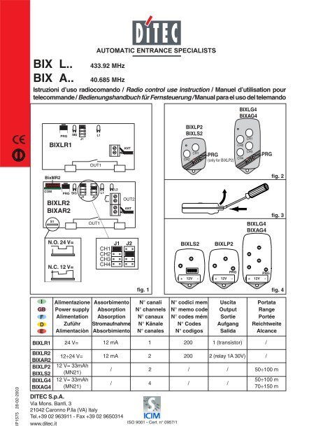
<strong>BIX</strong> L.. 433.92 MHz<br />
<strong>BIX</strong> A.. 40.685 MHz<br />
Istruzioni d’uso radiocomando / Radio control use instruction / Manuel d’utilisation pour<br />
telecommande / Bedienungshandbuch für Fernsteuerung / Manual para el uso del telemando<br />
I<br />
GB<br />
F<br />
D<br />
E<br />
COM<br />
<strong>BIX</strong>LR1<br />
<strong>BIX</strong>LR2<br />
<strong>BIX</strong>AR2<br />
<strong>BIX</strong>LP2<br />
<strong>BIX</strong>LS2<br />
<strong>BIX</strong>LG4<br />
<strong>BIX</strong>AG4<br />
PRG SIG<br />
<strong>BIX</strong>LR1<br />
BixMR2<br />
<strong>BIX</strong>LR2<br />
<strong>BIX</strong>AR2<br />
S1<br />
PRG SIG<br />
N.O. 24 V=<br />
N.C. 12 V=<br />
DITEC S.p.A.<br />
Via Mons. Banfi, 3<br />
21042 Caronno P.lla (VA) Italy<br />
Tel.+39 02 963911 - Fax +39 02 9650314<br />
www.ditec.it<br />
J1<br />
J1<br />
Alimentazione<br />
Power supply<br />
Alimentation<br />
Zuführ<br />
Alimentaciòn<br />
24 V=<br />
12÷24 V=<br />
12 V= 33mAh<br />
(MN21)<br />
12 V= 33mAh<br />
(MN21)<br />
L1<br />
OUT1<br />
J2<br />
OUT1<br />
L1<br />
CH1<br />
CH2<br />
CH3<br />
CH4<br />
L2<br />
J1<br />
ANT<br />
OUT2<br />
ANT<br />
J2<br />
Assorbimento<br />
Absorption<br />
Absorption<br />
Stromaufnahme<br />
Absorbimiento<br />
12 mA<br />
12 mA<br />
/<br />
/<br />
fig. 1<br />
N° canali<br />
N° channels<br />
N° canaux<br />
N° Känale<br />
N° canales<br />
1<br />
2<br />
2<br />
4<br />
ISO 9001 - Cert. n° 0957/1<br />
<strong>BIX</strong>LP2<br />
<strong>BIX</strong>LS2<br />
CH2<br />
ON<br />
CH1<br />
PRG<br />
(only for <strong>BIX</strong>LP2)<br />
<strong>BIX</strong>LS2 <strong>BIX</strong>LP2<br />
<strong>BIX</strong>LG4<br />
<strong>BIX</strong>AG4<br />
CH2<br />
CH4<br />
CH1<br />
CH3<br />
PRG<br />
<strong>BIX</strong>LG4<br />
<strong>BIX</strong>AG4<br />
12345678910<br />
PRG PRG<br />
+ 12V - + 12V - + 12V -<br />
N° codici mem<br />
N° memo code<br />
N° codes mém<br />
N° Codes<br />
N° codigos<br />
200<br />
200<br />
/<br />
/<br />
Uscita<br />
Output<br />
Sortie<br />
Aufgang<br />
Salida<br />
1 (transistor)<br />
2 (relay 1A 30V)<br />
/<br />
/<br />
Portata<br />
Range<br />
Portée<br />
Reichtweite<br />
Alcance<br />
/<br />
/<br />
fig. 2<br />
fig. 3<br />
fig. 4<br />
50÷100 m<br />
50÷100 m<br />
70÷150 m
2<br />
PRG<br />
1 1<br />
CH2<br />
Nuovo TX<br />
New TX<br />
CH1<br />
DITEC S.P.A. - IP1575 - <strong>BIX</strong> L / A<br />
CH2<br />
Attendere10 s<br />
Wait for 10 s<br />
2 s<br />
CH1<br />
PRG<br />
TX già memorizzato<br />
Stored TX (NO <strong>BIX</strong>LS2)<br />
Fig. 5<br />
PAESI CHE HANNO RECEPITO LA DIRETTIVA<br />
R&TTE 1999/5/CE<br />
COUNTRIES WHICH HAVE ADMITTED THE R&TTE<br />
DIRECTIVE, 1999/5/C, INTO THEIR LEGISLATION.<br />
COUNTRY<br />
AUSTRIA<br />
BELGIUM<br />
DENMARK<br />
ESTONIA<br />
FINLAND<br />
FRANCE<br />
GERMANY<br />
GREECE<br />
HUNGARY<br />
ICELAND<br />
IRELAND<br />
ITALY<br />
LICHTENSTEIN<br />
LUXEMBOURG<br />
NETHERLANDS<br />
NORWAY<br />
PORTUGAL<br />
SPAIN<br />
SWEDEN<br />
SWITZERLAND<br />
UNITED KINGDOM<br />
3<br />
STATUS<br />
NO LICENCE REQUIRED<br />
NO LICENCE REQUIRED<br />
NO LICENCE REQUIRED<br />
NO LICENCE REQUIRED<br />
NO LICENCE REQUIRED<br />
NO LICENCE REQUIRED<br />
NO LICENCE REQUIRED<br />
NO LICENCE REQUIRED<br />
NO LICENCE REQUIRED<br />
NO LICENCE REQUIRED<br />
NO LICENCE REQUIRED<br />
NO LICENCE REQUIRED<br />
NO LICENCE REQUIRED<br />
NO LICENCE REQUIRED<br />
NO LICENCE REQUIRED<br />
NO LICENCE REQUIRED<br />
NO LICENCE REQUIRED<br />
NO LICENCE REQUIRED<br />
NO LICENCE REQUIRED<br />
NO LICENCE REQUIRED<br />
NO LICENCE REQUIRED<br />
Tutti i diritti sono riservati<br />
I dati riportati sono stati redatti e controllati con la massima cura. Tuttavia<br />
non possiamo assumerci alcuna responsabilità per eventuali errori,<br />
omissioni o approssimazioni dovute ad esigenze tecniche o grafiche.<br />
All right reserved<br />
All data and specifications have been drawn up and checked with the<br />
greatest care. The manufacturer cannot however take any responsibility<br />
for eventual errors, ommisions or incomplete data due to technical or<br />
illustrative purposes.<br />
Touts droits reservés<br />
Les informations mentionnées dans ce catalogue ont été controlées<br />
avec la plus grande attention. Toutefois, nous déclinos toute<br />
responsabilité en cas d’erreurs, omissions ou approximations dépendant<br />
d’exigences techniques ou graphiques.<br />
Alle Rechte vorbehalten<br />
Die wiedergegebenen Daten wurden mit höchster Sorgfalt<br />
zusammengestellt und überprüft. Es kann jedoch keinerlei<br />
Verantwortung für eventuelle Fehler, Auslassungen oder Näherungen,<br />
die technischen oder graphischen Notwendigkeiten zuzuschreiben sind,<br />
übernommen werden.<br />
Todos los derechos son reservados<br />
Los datos que se indican han sido redactados y controlados con la<br />
màxima atenciòn. Sin embargo no podemos asumir ninguna<br />
responsabilidad por eventuales errores, omisiones o aproximaciones<br />
debidas a exigencias técnicas o gràficas.<br />
2<br />
AVVERTENZE GENERALI PER LA SICUREZZA<br />
Le presenti avvertenze sono parte integrante ed essenziale del prodotto<br />
e devono essere consegnate all’utilizzatore.<br />
Tenere fuori dalla portata dei bambini i radiocomandi, per evitare che la porta<br />
o cancello motorizzati possa essere azionata involontariamente.<br />
Non usare il radiocomando senza avere la completa visuale della porta o<br />
cancello motorizzati.<br />
I materiali dell’imballaggio (plastica, polistirolo, ecc.) e le batterie non vanno<br />
dispersi nell’ambiente e non devono essere lasciati alla portata dei bambini in<br />
quanto potenziali fonti di pericolo.<br />
DICHIARAZIONE CE DI CONFORMITÀ<br />
Fabbricante: DITEC S.p.A. - via Mons. Banfi, 3 - 21042 Caronno<br />
Pertusella (VA) – ITALY.<br />
Dichiara che i radiocomandi <strong>BIX</strong>LR1, <strong>BIX</strong>LR2, <strong>BIX</strong>LS2, <strong>BIX</strong>LP2 e<br />
<strong>BIX</strong>LG4 (433.92 MHz) e <strong>BIX</strong>AR2 e <strong>BIX</strong>AG4 (40.685 MHz) sono<br />
conformi alle condizioni delle seguenti direttive CE: Direttiva R&TTE<br />
1999/5/CE, Direttiva EMC 89/336/CEE e Direttiva bassa tensione<br />
73/23/CEE.<br />
Caronno Pertusella, 31-08-2000. Fermo Bressanini<br />
(Presidente)<br />
1. Trasmettitore<br />
I radiocomandi serie <strong>BIX</strong> sono preposti per l’attivazione di automatismi<br />
per vani passaggio e rispondono ai requisiti essenziali stabiliti<br />
dalla direttiva 1999/5/CE R&TTE.<br />
Il trasmettitore è dotato di un codice individuale (Rolling Code) che<br />
lo distingue da qualsiasi altro trasmettitore.<br />
2. Ricevitore<br />
I ricevitori sono previsti per essere inseriti direttamente nei quadri<br />
elettrici DITEC. Solo i <strong>BIX</strong>LR2 e <strong>BIX</strong>AR2 possono essere usati con<br />
la base porta scheda CONT1. Il ricevitore può ricevere i codici di<br />
tutti i trasmettitori, ma attiverà l’uscita di comando solo se il codice<br />
ricevuto é presente nella lista dei codici abilitati (max. 200 codici).<br />
Verificare che la memoria BixMR2 sia inserita sul connettore COM<br />
del ricevitore <strong>BIX</strong>LR2/AR2.<br />
Attenzione: l’inserimento e l’estrazione del BixMR2 devono<br />
essere effettuati in assenza di alimentazione.<br />
I ricevitori <strong>BIX</strong>LR1 e <strong>BIX</strong>LR2 sono dotati di antenna (filo rigido L=<br />
173 mm). In alternativa è possibile collegare l’antenna accordata<br />
<strong>BIX</strong>LA. I ricevitori <strong>BIX</strong>AR2 devono essere collegati all’antenna<br />
accordata <strong>BIX</strong>AA. Per collegare l’antenna al ricevitore usare cavo<br />
coassiale RG58 (max. 10 m).<br />
L’antenna va posizionata il più in alto possibile, lontano da strutture<br />
metalliche (nel lampeggiante LAMP e LAMPH è previsto un morsetto<br />
per il collegamento dell’antenna).<br />
3. ABILITAZIONE TRASMETTITORI (Fig. 5)<br />
3.1 Premere il pulsante PRG sul ricevitore (alimentato), il led segnalazione<br />
SIG si accende, oppure premere PRG di un<br />
trasmettitore già memorizzato (BixLP2, BixLG4 o BixAG4)<br />
per almento 2 s (entro la portata del ricevitore alimentato),<br />
facendo attenzione a non memorizzare i nuovi trasmettitori<br />
su impianti presenti nelle vicinanze.<br />
3.2 Solo con <strong>BIX</strong>LS2. Selezionare mediante i 10 dip-switch il<br />
codice di codifica desiderato, tra i 1024 possibili.<br />
3.3 Effettuare una trasmissione premendo uno qualsiasi dei pulsanti<br />
CH del nuovo trasmettitore. Il trasmettitore viene così abilitato. Durante<br />
questa fase il led segnalazione SIG lampeggia. Quando il<br />
led torna acceso fisso è possibile abilitare un nuovo trasmettitore.<br />
Abilitare tutti i nuovi trasmettitori effettuando una trasmissione<br />
come indicato sopra.<br />
N.B.: (Solo con <strong>BIX</strong>LS2) E’ sufficiente memorizzare un solo<br />
TX. Tutti i TX aventi lo stesso codice sono abilitati.<br />
3.4 L’uscita dalla procedura avviene in modo automatico dopo 10 s<br />
dall’ultima trasmissione oppure premendo nuovamente il tasto<br />
PRG (il led SIG si spegne).<br />
4. SELEZIONE CANALI<br />
Per attivare l’uscita 1 (OUT1) del ricevitore selezionare con il<br />
ponticello J1 il canale desiderato. Per attivare l’uscita 2 (OUT2) del<br />
ricevitore selezionare con il ponticello J2 il canale desiderato. Canali<br />
preimpostati: CH1 attiva OUT1, CH2 attiva OUT2. I led L1 e<br />
L2 indicano rispettivamente l’attivazione dell’uscita 1 e 2.<br />
5. Disabilitazione di tutti i trasmettitori<br />
- Tenere premuto il pulsante PRG sul ricevitore, finché il led SIG<br />
comincia a lampeggiare.<br />
- Premere nuovamente il pulsante PRG entro 6 s per confermare<br />
l’operazione. La conferma viene segnalata da un lampeggio<br />
del led SIG a frequenza più elevata.<br />
ITALIANO
ENGLISH<br />
GENERAL SAFETY PRECAUTIONS<br />
The following precautions are an integral and essential part of<br />
the product and must be supplied to the user.<br />
Keep remote control out of the reach of children, in order to avoid<br />
possible involuntary activation of the motorised door or gate.<br />
Do not use remote control out of the visual of the door and gate.<br />
Packaging materials (plastic, polystyrene, etc.) and batteries must not<br />
be allowed to litter the environment and must be kept out of the reach<br />
of children for whom they may be a source of danger.<br />
EC DECLARATION OF CONFORMITY<br />
Manufacturer: DITEC S.p.A. - via Mons. Banfi, 3 - 21042 Caronno<br />
Pertusella (VA) – ITALY.<br />
Herewith declares that the radio controls <strong>BIX</strong>LR1, <strong>BIX</strong>LR2, <strong>BIX</strong>LS2,<br />
<strong>BIX</strong>LP2 e <strong>BIX</strong>LG4 (433.92 MHz) and <strong>BIX</strong>AR2 and <strong>BIX</strong>AG4 (40.685<br />
MHz) are in conformity with the provisions of the following EC directives:<br />
R&TTE Directive 1999/5/EC, EMC Directive 89/336/EEC and<br />
Low Voltage Directive 73/23/EEC.<br />
Caronno Pertusella, 31-08-2000. Fermo Bressanini<br />
(Chairman)<br />
1. Transmitter<br />
The <strong>BIX</strong> series of remote controls are designed for the activation of<br />
automatic accesses and are built in compliance with the R&TTE<br />
Directive, 1999/5/C.<br />
The transmitter is provided with its own code (Rolling code) different<br />
from that of any other transmitter.<br />
2. Receiver<br />
Receivers are designed for directly inserting into DITEC electrical<br />
boards. Only the <strong>BIX</strong>LR2 and <strong>BIX</strong>AR2 version can be used with<br />
CONT1 card holders. The receiver can receive the codes from all<br />
transmitters but will only respond upon receiving a code which is<br />
included in its file of authorised codes (max. 200 codes).<br />
Check that memory BixMR2 is inserted on COM connector of<br />
receiver <strong>BIX</strong>LR2/AR2.<br />
Attention: Insertion and removal of the <strong>BIX</strong>MR module must<br />
be made with the unit powered off.<br />
The receivers <strong>BIX</strong>LR1 and <strong>BIX</strong>LR2 are equipped with a 173 mm<br />
long rigid antenna. Alternatively, it may be linked up to a <strong>BIX</strong>LA. The<br />
<strong>BIX</strong>AR2 receivers must be linked up to the <strong>BIX</strong>AA tuned antenna.<br />
Tuned antenna by means of an RG58 coaxial cable with a maximum<br />
length of 10 metres.<br />
The antenna must be mounted as high up as possible, away from<br />
any metal structures (the LAMP and LAMPH flashing lights are<br />
provided with a clamp for linking up of the antenna).<br />
3. ENABLING THE TRANSMITTERS<br />
3.1 Press the PRG button on the receiver (powered). The SIG<br />
warning LED lights up, or press the PRG of a previously<br />
stored transmitter (BixLP2, BixLG4 or BixAG4) for at least 2<br />
s (within the range of the powered receiver) paying attention<br />
not to store the new transmitters in nearby systems.<br />
3.2 Only with <strong>BIX</strong>LS2. Select the desired code among the 1024<br />
possible ones by means of the 10 dip-switches.<br />
3.3 Carry out a transmission by pressing any of the CH buttons<br />
of the new transmitter.<br />
During this operation the SIG LED will be flashing.<br />
A new transmitter can be enabled once the SIG LED has<br />
stopped flashing and become fixed.<br />
Enable all the transmitters by transmitting a signal as above<br />
mentioned.<br />
Note: (only with <strong>BIX</strong>LS2) Only one TX needs be memorized.<br />
All TXs having the same code are enabled.<br />
3.4 Exiting from the transmitter enabling function will occur automatically<br />
10 seconds after last transmission or by pressing<br />
PRG again (the SIG LED will then go off).<br />
4. SELECTING THE CHANNEL<br />
Output 1 (OUT1) on the receiver is activated by the selected channel<br />
via the jumper on J1 of the receiver. Output 2 (OUT2)) on the<br />
receiver is activated by the selected channel via the jumper on J2<br />
of the receiver. Default channels: CH1 actives OUT1, CH2 actives<br />
OUT2. LEDs L1 and L2 signal that output 1 and 2, respectively,<br />
have been activated.<br />
5. Disabling all transmitters<br />
- Keep the PRG button on the receiver until the SIG LED starts flashing.<br />
- Within 6 seconds press the PRG button again to confirm the<br />
operation. Confirmation will be signalled by the SIG LED flashing<br />
at a faster rate.<br />
3<br />
CONSIGNES GENERALES DE SECURITE<br />
Ces consignes sont partie intégrante et essentielle du produit<br />
et doivent être remises à l’utilisateur.<br />
Garder hors le portée des enfants les radiocommandes afin d’éviter<br />
que la porte ao le portail automatisés puissent être actionnés involontairement.<br />
N’utilisez pas la radiocommande si vous ne voyez pas<br />
entierement la porte au portail motorisés.<br />
Les materiaux de l’emballage (plastique, polystyréne, etc ne doivent<br />
pas être abandonnés dand la nature et ne doivent pas être laissés à<br />
la portée des enfants, car ils sont une source potentielle de danger.<br />
DECLARATION CE DE CONFORMITE<br />
Fabricant: DITEC S.p.A. - via Mons. Banfi, 3 - 21042 Caronno<br />
Pertusella (VA) – ITALY.<br />
Déclare ci-après que les radiocommandes <strong>BIX</strong>LR1, <strong>BIX</strong>LR2, <strong>BIX</strong>LS2,<br />
<strong>BIX</strong>LP2 e <strong>BIX</strong>LG4 (433.92 MHz) et <strong>BIX</strong>AR2 et <strong>BIX</strong>AG4 (40.685<br />
MHz) sont conforme aux dispositions des directives CEE suivantes:<br />
Directive R&TTE 1999/5/CE, Directive EMC 89/336/CEE et Directive<br />
basse tension 73/23/CEE.<br />
Caronno Pertusella, 31-08-2000. Fermo Bressanini<br />
(Président)<br />
1. Émetteur<br />
Les télécommandes radio de la série <strong>BIX</strong> permettent d’activer des<br />
automatismes pour les ouvertures de passage et répondent aux<br />
exigences essentielles de la directive 1999/5/CE R&TTE.<br />
L’émetteur est doté d’un code individuel (Rolling Code) qui le distingue<br />
de tout autre émetteur.<br />
2. Récepteurs<br />
Les récepteurs sont conçus pour être mis en place directement dans<br />
les tableaux de commande DITEC. Seul les <strong>BIX</strong>LR2 et <strong>BIX</strong>AR2 peut<br />
être utilisé avec les bases porte cartes CONT1. Le récepteur peut<br />
recevoir les codes de tous les émetteurs, mais il n’activera la sortie de<br />
commande que si le code reçu est présent dans la liste des codes<br />
autorisés (max. 200 codes).<br />
Vérifier si la mémoire BixMR2 est introduite sur le connecteur<br />
COM du récepteur <strong>BIX</strong>LR2/AR2.<br />
Attention: l’enfichage et l’extraction du module mémoire <strong>BIX</strong>MR<br />
doivent s’effectuer sans alimentation.<br />
Les récepteurs <strong>BIX</strong>LR1 et <strong>BIX</strong>LR2 sont doté d’une antenne (fil rigide<br />
L = 173 mm). En alternative, il est possible de relier l’antenne accordée<br />
<strong>BIX</strong>LA. Les récepteurs <strong>BIX</strong>AR2 doivent être reliés à l’antenne<br />
accordée <strong>BIX</strong>AA. Pour relier l’antenne au récepteur, utiliser un câble<br />
coaxial RG58 (max. 10 m).<br />
L’antenne doit être installée le plus haut possible, loin de structures<br />
métalliques (les clignotants LAMP et LAMPH sont dotés d’une borne<br />
pour le branchement de l’antenne).<br />
3. ACTIVATION ÉMETTEURS<br />
3.1 Appuyer sur le bouton PRG du récepteur (sous tension), la<br />
led de signalisation SIG s’allume ou bien appuyer sur PRG<br />
d’un transmetteur déjà mémorisé (BixLP2, BixLG4 ou BixAG4)<br />
pendant au moins 2 sec. (dans la portée du récepteur sous<br />
tension), en veillant à ne pas mémoriser les transmetteurs<br />
nouveaux sur des installations présentes à proximité.<br />
3.2 Uniquement avec <strong>BIX</strong>LS2. A l’aide des commutateurs DIP 10,<br />
sélectionner le code désiré parmi les 1024 codes possibles.<br />
3.3 Effectuer une transmission en appuyant sur l’un quelconque<br />
des boutons CH du nouvel émetteur. L’émetteur est activé.<br />
Pendant cette phase, le voyant de signalisation SIG clignote.<br />
Quand le voyant redevient fixe, il est possible d’activer<br />
le nouvel émetteur. Activer tous les émetteurs en effectuant<br />
une transmission comme dit plus haut.<br />
N.B.: (Uniquement avec <strong>BIX</strong>LS2) Il suffit de mémoriser un seul<br />
émetteur. Tous les émetteurs ayant le même code sont activés.<br />
3.4 Le système quitte de toute façon la procédure de façon<br />
automatique 10 s après la dernière transmission ou en appuyant<br />
de nouveau sur le button PRG (le voyant SIG s’éteint).<br />
4. SÉLECTION CANAUX<br />
La sortie 1 (OUT1) du récepteur est activée par le canal sélectionné<br />
par une barrette sur J1. La sortie 2 (OUT2) du récepteur est activée<br />
par le canal sélectionné par une barrette sur J2. Canaux préposée:<br />
CH1 activé OUT1, CH2 activé OUT2. Les voyants L1 et L2 indiquent<br />
respectivement l’activation de la sortie 1 et 2.<br />
5. Désactivation de tous les émetteurs<br />
- Maintenir enfoncé le bouton PRG sur le récepteur, jusqu’à ce<br />
que le voyant SIG commence à clignoter.<br />
- Appuyer de nouveau sur le bouton PRG dans les 6 s suivantes<br />
pour confirmer l’opération. La confirmation est signalée par un<br />
clignotement du voyant SIG à une fréquence plus élevée.<br />
DITEC S.P.A. - IP1575 - <strong>BIX</strong> L / A<br />
FRANÇAIS
DEUTSCH<br />
ALLGEMEINE SICHERHEITSHINWEISE<br />
Diese Hinweise sind als wesentlicher Bestandteil des Produktes<br />
dem Benutzer auszuhändigen.<br />
Funk-Fernsteuerungen von Kindern fernhalten, damit der Torantrieb<br />
nicht unbeabsichtig ausgelöst werden kann. Die Fernsteuerung nicht<br />
verwenden ob das Tor und das Gittertor nicht sehen.<br />
Das Verpackunsmaterial (Kunststoff, Polystyrol, usw. ) ist vorschriftsmäßig<br />
zu entsorgen. Es ist von Kindern fernzuhalten, da es eine Gefahr<br />
für sie bedeutet.<br />
EG-KONFORMITÄTSERKLÄRUNG<br />
Hersteller: DITEC S.p.A. - via Mons. Banfi, 3 - 21042 Caronno Pertusella<br />
(VA) – ITALY.<br />
erklärt hiermit, daß die Fernsteuerungen <strong>BIX</strong>LR1, <strong>BIX</strong>LR2, <strong>BIX</strong>LS2,<br />
<strong>BIX</strong>LP2 e <strong>BIX</strong>LG4 (433.92 MHz) und <strong>BIX</strong>AR2 und <strong>BIX</strong>AG4 (40.685<br />
MHz) mit den einschlägigen Bestimmungen folgender EG-Rchtlinien<br />
übereinstimmen: R&TTE-Richtlinie 1999/5/EWG, EMC-Richtlinie 89/<br />
336/EWG und Niederspannungsrichtlinie 73/23/EWG.<br />
Caronno Pertusella, 31-08-2000. Fermo Bressanini<br />
(Präsident)<br />
1. Sender<br />
Die Fernsteuerungen der Typenreihe <strong>BIX</strong> dienen der Aktivierung<br />
von Tür- und Torantrieben und entsprechen den wesentlichen Anforderungen<br />
der Richtlinie 1999/5/CE R&TTE.<br />
Der Sender verfügt über einen individuellen Code (Rolling Code),<br />
der ihn von allen anderen unterscheidet.<br />
2. Empfänger<br />
Die Empfänger sind für den direkten Einbau in die DITEC-Steuerungen<br />
vorgesehen. Nur die <strong>BIX</strong>LR2 und <strong>BIX</strong>AR2 können mit den<br />
Basisports der Platinen CONT1 verwendet werden. Der Empfänger<br />
kann die Codes aller Sender empfangen, aber aktiviert den Steuerausgang<br />
nur, wenn der empfangene Code in der Liste der aktivierten<br />
Codes (max. 200) enthalten ist.<br />
Prüfen, dass der Speicher BixMR2 an den COM-Anschluss des<br />
Empfängers <strong>BIX</strong>LR/AR2 angeschlossen ist.<br />
Achtung: Beim Einsetzen und Herausnehmen des Speichermoduls<br />
<strong>BIX</strong>MR darf kein Strom zugeführt werden.<br />
Die Empfänger <strong>BIX</strong>LR1 und <strong>BIX</strong>LR2 verfügen über eine Antenne<br />
(starrer Draht L = 173 mm). Als Alternative kann die abgestimmte<br />
Antenne <strong>BIX</strong>LA angeschlossen werden. Die Empfänger <strong>BIX</strong>AR2<br />
müssen mit der abgestimmten Antenne <strong>BIX</strong>AA verbunden werden.<br />
Zum Anschluß der Antenne ein Koaxialkabel RG58 (max. 10 m)<br />
verwenden.<br />
Die Antenne muß so hoch als möglich und weit von Metallkonstruktionen<br />
entfernt installiert werden (im Blinklicht LAMP und<br />
LAMPH ist eine Anschlußklemme für die Antenne vorgesehen).<br />
3. AKTIVIERUNG DER SENDER<br />
3.1 PRG-Taste am (mit Strom versorgten) Empfänger drücken,<br />
die LED-Anzeige SIG leuchtet auf oder mindestens 2 Sekunden<br />
lang die PRG-Taste eines bereits programmierten<br />
Senders (BixLP2, BixLG4 oder BixAG4) drücken (innerhalb<br />
der Reichweite des mit Strom versorgten Empfängers),<br />
wobei darauf zu achten ist, dass die neuen Sender nicht<br />
auf Anlagen programmiert werden, die sich in der Nähe<br />
befinden.<br />
3.2 Nur bei <strong>BIX</strong>LS2. Über die 10 Dip-Schalter die gewünschte<br />
Codierung aus den 1024 möglichen Codes auswählen.<br />
3.3 Führen Sie eine Übertragung durch, indem Sie eine beliebige<br />
Taste CH des neuen Senders drücken. Durch Betätigen einer<br />
jeder der Kanaltasten des Senders, ein Signal senden. Auf<br />
diese Weise wird er aktiviert. Während dieser Phase blinkt<br />
die Led SIG. Sobald sie wieder konstant leuchtet, kann ein<br />
neuer Sender aktiviert werden. Alle Sender nach der gleichen<br />
Vorgehensweise aktivieren wie obengennant.<br />
Hinweis: (nur bei <strong>BIX</strong>LS2) Es reicht aus, nur ein TX zu speichern,<br />
denn dann werden alle TX mit dem gleichen Code aktiviert.<br />
3.4 Das Verfahren wird 10 s nach der letzten Sendung automatisch<br />
verlassen oder durch erneutes Drücken der Taste PRG<br />
(die Led SIG löscht ab).<br />
4. KANALANWAHL<br />
Der Ausgang 1 (OUT1) wird vom angewählten Kanal mittels Brücke<br />
auf J1 aktiviert. Der Ausgang 2 (OUT2) wird vom angewählten Kanal<br />
mittels Brücke auf J2 aktiviert. Vorangelegte Känale: CH1 aktiviert<br />
OUT1, CH2 aktiviert OUT2. Die Led L1 und L2 zeigen die Aktivierung<br />
jeweils der Ausgänge 1 und 2 an.<br />
5. Deaktivierung aller Sender<br />
- Die Taste PRG ca. 2s drücken, bis die Led SIG zu blinken beginnt.<br />
- Die Taste PRG innerhalb von 6s zur Bestätigung nochmals<br />
drücken. Die Bestätigung wird von der Led SIG durch schnelleres<br />
Blinken angezeigt.<br />
DITEC S.P.A. - IP1575 - <strong>BIX</strong> L / A<br />
4<br />
ADVERTENCIAS GENERALES DE SEGURIDAD<br />
Las siguientes advertencias forman parte integrante y esencial<br />
del producto y deben ser entregadas al usuario.<br />
Conservar fuera del alccance de los niños el telemando para evitar el<br />
accionamiento accidental. No utilizar el radiomando si no se tiene<br />
una visiòn completa de la puerta o de los portal motorizadas.<br />
El material de embalaje (plàstico, poliestirol, etc.) debe desecharse<br />
sin causar daño al medio ambiente y mantenerse fuera del alcance<br />
de los niños, porque es una potencial fuente de peligro.<br />
DECLARACIÓN CE DE CONFORMIDAD<br />
Fabricante: DITEC S.p.A. - via Mons. Banfi, 3 - 21042 Caronno<br />
Pertusella (VA) – ITALY.<br />
Declara que los radiomando <strong>BIX</strong>LR1, <strong>BIX</strong>LR2, <strong>BIX</strong>LS2, <strong>BIX</strong>LP2 e<br />
<strong>BIX</strong>LG4 (433.92 MHz) y <strong>BIX</strong>AR2 y <strong>BIX</strong>AG4 (40.685 MHz) son conformes<br />
con las condiciones de las siguientes directivas CE: Directiva<br />
R&TTE 1999/5/CE, Directiva EMC 89/336/CEE y Directiva baja tensión<br />
73/23/CEE.<br />
Caronno Pertusella, 31.08.2000. Fermo Bressanini<br />
(Presidente)<br />
1. Transmisor<br />
Los radiomandos de serie <strong>BIX</strong> se utilizan para la activación de<br />
aparatos automatizados previstos para áreas de paso y están conformes<br />
con los requisitos básicos establecidos por la directiva 1999/5/<br />
CE R&TTE.El transmisor posee un código individual (Rolling Code)<br />
que lo distingue de cualquier otro transmisor.<br />
2. Receptor<br />
Los receptores están pensados para ser introducidos directamente en<br />
los cuadros eléctricos DITEC. Solamente <strong>BIX</strong>LR2 y <strong>BIX</strong>AR2 pueden<br />
ser usados con las bases porta-fichas CONT1. El receptor puede<br />
recibir los códigos de todos los transmisores, pero activará la salida de<br />
mando solamente si el código recibido está presente en la lista de los<br />
códigos habilitados (máx. 200 códigos).<br />
Verificar que la memoria BixMR2 esté insertada en el conector<br />
COM del receptor <strong>BIX</strong>LR2/AR2.<br />
Atención: la inserción y extracción del módulo memoria <strong>BIX</strong>MR<br />
deben ser efectuadas sin alimentación.<br />
Los receptores <strong>BIX</strong>LR1 y <strong>BIX</strong>LR2 posee una antena (alambre rígido<br />
L= 173 mm). Como alternativa es posible conectar la antena facilitada<br />
<strong>BIX</strong>LA. Los receptores <strong>BIX</strong>AR2 deben ser conectados a la antena<br />
sintonizada <strong>BIX</strong>AA. Para conectar la antena al receptor usar un<br />
cable coaxial RG58 (máx.10 m).<br />
La antena ha de ser colocada lo más alto posible, lejos de estructuras<br />
metálicas ( en el indicador LAMP y LAMPH tenemos un borne<br />
para la conexión de la antena).<br />
3. HABILITACIÓN DE LOS TRANSMISORES<br />
3.1 Presionar el pulsador PRG en el receptor (bajo tensión), el led<br />
de señalización SIG se enciende o bien presionar PRG de un<br />
transmisor memorizado (BixLP2, BixLG4 o BixAG4) por lo menos<br />
durante 2 s (dentro del alcance del receptor bajo tensión),<br />
asegurándose de no memorizar los nuevos transmisores en<br />
los equipos que se encuentran en las cercanías.<br />
3.2 Sólo con <strong>BIX</strong>LS2. Seleccionar mediante los 10 conmutadores<br />
DIP el código de codificación deseado entre los 1024 posibles.<br />
3.3 Efectuar una transmisión presionando un pulsador cualquiera<br />
CH del nuevo transmisor. Llevar a cabo una transmisión<br />
pulsando uno de los botones de canal del transmisor. De<br />
esta manera se habilita el transmisor. Durante esta fase el<br />
led señalización SIG relampaguea. Cuando el led se enciende<br />
de nuevo de forma fija es posible habilitar un nuevo<br />
transmisor. Habilitar todos los transmisores efectuando una<br />
transmisión como dicho mas arriba.<br />
N.B.: (Sólo con <strong>BIX</strong>LS2) Basta con memorizar un solo TX.<br />
Todos los TX que poseen los mismos códigos están habilitados.<br />
3.4 La salida de este procedimiento se realiza automática después<br />
de 10 segundos desde la última transmisión o bien presionando<br />
nuevamente el pulsador PRG (el led SIG se apaga).<br />
4. SELECCIÓN DE LOS CANALES<br />
La salida 1(OUT1) del receptor se activa a través del canal seleccionado<br />
mediante un conector puente en J1. La salida 2 (OUT2) del<br />
receptor se activa a través del canal seleccionado mediante un conector<br />
puente en J2. Canales preseleccionados: CH1 activa OUT1, CH2<br />
activa OUT2. Los led L1 y L2 indican respectivamente la activación<br />
de la salida 1 y 2.<br />
5. Deshabilitación de todos los transmisores<br />
- Mantener pulsado el botón PRG en el receptor hasta que el led<br />
SIG empiece a relampaguear.<br />
- Pulsar nuevamente el botón PRG antes de que pasen 6 segundos<br />
para confirmar la operación. La confirmación se señala con un<br />
destello del led SIG con una frecuencia más elevada.<br />
ESPAÑOL