Reference Manual BioTrak Datalink and Gas ... - Biodownloads
Reference Manual BioTrak Datalink and Gas ... - Biodownloads
Reference Manual BioTrak Datalink and Gas ... - Biodownloads
- No tags were found...

Create successful ePaper yourself
Turn your PDF publications into a flip-book with our unique Google optimized e-Paper software.
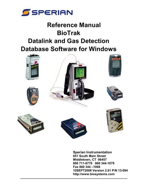
<strong>Reference</strong> <strong>Manual</strong><strong>BioTrak</strong><strong>Datalink</strong> <strong>and</strong> <strong>Gas</strong> DetectionDatabase Software for WindowsSperian Instrumentation651 South Main StreetMiddletown, CT 06457800 711-6776 860 344-1079Fax 860 344 –106810SEPT2008 Version 2.61 P/N 13-094http://www.biosystems.com1
BIOSYSTEMS GAS DETECTORS HAVE BEEN DESIGNED FOR THEDETECTION OF DEFICIENCIES OF OXYGEN, ACCUMULATIONS OFFLAMMABLE GASES AND VAPORS AND ACCUMULATIONS OFTOXIC VAPORS.IN ORDER TO ASSURE THAT THE USER IS PROPERLYWARNED OF POTENTIALLY DANGEROUSATMOSPHERIC CONDITIONS, IT IS ESSENTIAL THATTHE INSTRUCTIONS IN THE REFERENCE MANUAL FORTHE SPECIFIC GAS DETECTOR BE READ, FULLYUNDERSTOOD, AND FOLLOWED.AVERTISSEMENT: LIRE ATTENTIVEMENT LES INSTRUCTIONS AVANTDE METTRE EN MARCHE.<strong>BioTrak</strong> <strong>Reference</strong> <strong>Manual</strong>Version 2.61Copyright 2008byBiosystemsMiddletown, Connecticut 06457All rights reserved.No page or part of this operation manual may be reproduced in any formwithout written permission of the copyright owner shown above.All rights reserved to correct typographical errors.2
Table of ContentsINTRODUCTION ................................................................................... 41. INSTALLING BIOTRAK DOWNLOAD SOFTWARE.................. 51.1 PC REQUIREMENTS .................................................................................... 51.2 INSTALLING BIOTRAK ON WINDOWS 95, 98, 2000, XP OR NT..................... 52. USING BIOTRAK DATALINK SOFTWARE ............................... 62.1 SERIAL PORT CONNECTION ......................................................................... 62.2 INFRARED PORT CONNECTION ..................................................................... 62.2.1 Infrared Port Activation.......................................................................... 72.3 MAIN MENU OPTIONS.................................................................................. 73. FILE MENU .................................................................................. 73.1 GENERAL ................................................................................................... 73.2 FILE / OPEN................................................................................................ 83.3 FILE / OPTIONS ........................................................................................... 83.3.1 Detection Options.................................................................................. 83.3.2 Printing Options..................................................................................... 83.3.3 Data Export Options.............................................................................. 93.3.4 Toxi/Oxy Ultra Options.......................................................................... 93.3.5 Language Options................................................................................. 93.3.6 Auto Download Options ........................................................................ 93.3.7 Infrared.................................................................................................. 93.3.8 ToxiPro/Ltd.......................................................................................... 103.4 FILE / EXIT................................................................................................ 104. SOFTWARE USE / INSTRUMENTS MENU ............................. 104.1 CONNECTING THE PHD5, PHD ULTRA, TOXI/OXY ULTRA TO THE PC............ 104.2 AUTO DOWNLOAD (FOR PHD5, PHD ULTRA AND TOXI ULTRA) .................... 114.3 CONNECTING THE CANNONBALL3, MULTIPRO, MULTIVISION, PHD LITE,TOXIPRO/LTD AND TOXIVISION EX ....................................................................... 124.4 DOWNLOAD .............................................................................................. 124.4.1 Session Summary File Menu .............................................................. 134.4.1.1 File / Save the Data File .......................................................................134.4.1.2 File / Options ........................................................................................134.4.1.3 File / Graph options ..............................................................................134.4.2 Lower Control Bar ............................................................................... 144.4.2.1 Details Button .......................................................................................144.4.2.2 Alarms ..................................................................................................154.4.2.3 Graphs..................................................................................................154.4.2.4 Data Table Button.................................................................................164.4.2.5 Viewing Alarm Legend..........................................................................174.5 CONFIGURATION ....................................................................................... 174.5.1 Configuration / Alarm Tab ................................................................... 174.5.2 Configuration / Datalogger Tab ........................................................... 184.5.3 Configuration / Features Tab............................................................... 184.5.4 Configuration / Auto Calibration Tab ................................................... 184.5.5 Configuration / Calibration History Tab ............................................... 194.5.6 Configuration / User/Locations Tab..................................................... 193
4.5.7 Configuration Controls ........................................................................ 194.6 CLEAR DATALOGGER MEMORY.................................................................. 204.7 SETTING INSTRUMENT DATE AND TIME ....................................................... 205. COMPUTER AND HELP MENUS ............................................. 205.1 COMPUTER MENU ..................................................................................... 205.2 HELP MENU.............................................................................................. 215.2.1 <strong>BioTrak</strong> Help File................................................................................. 215.2.2 Help Contents <strong>and</strong> Index..................................................................... 215.2.3 Internet Support .................................................................................. 215.2.4 About <strong>BioTrak</strong> ..................................................................................... 21SPERIAN INSTRUMENTATION WARRANTY GAS DETECTIONPRODUCTS......................................................................................... 23IntroductionBiosystems <strong>Datalink</strong> Kits consist of a copy of Biosystems' <strong>BioTrak</strong> Software for theBiosystems Family of <strong>Gas</strong> Detectors <strong>and</strong> a software instruction manual.A computer interface cable is also included for connection of the PhD5 <strong>and</strong> PhD Ultra to aserial port on the user's IBM compatible computer. The Toxi Ultra serial cable is built into itsdata dock. The PhD Lite, Cannonball3 <strong>and</strong> MultiVision interfaces require an infraredtransceiver. This transceiver can be purchased from Biosystems or a third party vendor.Most of portable computers manufactured today have an infrared transceiver. <strong>BioTrak</strong> iscapable of running in Windows 95, 98, 2000, XP <strong>and</strong> NT.<strong>BioTrak</strong> is menu driven for easy use. The software allows your Biosystems gas detector<strong>and</strong> your computer to communicate. It serves two basic functions: retrieving storedinformation from the gas detector <strong>and</strong> using the computer to "configure" the gas detector.Optional instrument setups are created by "filling out" configuration forms displayed by thesoftware. Most functions (such as downloading stored information from the instrument toyour PC) are automatic or as easy as pushing a button. The software is designed to helpyou along.Once the session information has been "downloaded" to the computer, it may be used for avariety of purposes. Data may be displayed <strong>and</strong> reviewed in detail through the SessionSummary form, or used to automatically generate reports, tables, <strong>and</strong> time history graphs.It is also possible to export data session records to formatted text for import into othersoftware applications. Another option is to simply retain downloaded records as computerfiles to provide a permanent record of your gas detection-monitoring program.The best way to learn the software is to use it!4
1. Installing <strong>BioTrak</strong>Download Software1.1 PC RequirementsThe minimum PC requirements for<strong>BioTrak</strong> are as follows:•Pentium Processor 366mHz or better orequivalent.•32MB RAM.•Windows 95/98/2000/NT4.0 (w/ServicePack 5 or higher)/XP•30MB hard drive disk space.Note: Windows XP or Windows 2000with Service Pack 3 is required forinstruments that communicate viainfrared (Cannonball3, MultiPro,MultiVision, PhD Lite, ToxiPro/Ltd <strong>and</strong>ToxiVision EX).1.2 Installing <strong>BioTrak</strong> onWindows 95, 98, 2000, XP or NTTo install <strong>BioTrak</strong> software to a PC usingWindows 95, 98, 2000, XP or NT:1. Insert the <strong>BioTrak</strong> CD into the PC’sCD drive. If the installation does notstart automatically, click on your CDdrive in Windows Explorer. Thereare subfolders for the English <strong>and</strong>French installations. Click on theappropriate folder <strong>and</strong> then click onthe “Setup.exe” file to begin theinstallation.2. Click “Next” at the Welcome screen.The License Agreement screen willbe shown.3. Read the License Agreement. If youagree to the terms set forth in theagreement, click “I accept the termsin the license agreement” followed by“Next”. Failure to accept the terms ofthe license agreement will cause theinstallation to terminate. InstallationTips will then be shown.↓4. Click “Next”. The CustomerInformation screen will then beshown.5
5. Fill in the User Name <strong>and</strong>Organization <strong>and</strong> decide whether the<strong>BioTrak</strong> program should be availableto all users or only you. Then click“Next”. The destination folder screenwill then be shown.↓6. Click “Next” to install <strong>BioTrak</strong> into thedefault location at the “C:\ ProgramFiles \ BIOSYSTEMS \ <strong>BioTrak</strong>”folder. If you wish to store thedatabase in a different directory usethe “Change” button <strong>and</strong> select adifferent destination. Then click“Next”. The Setup Type screen willbe shown.7. Biosystems recommends selectingthe “Typical” installation. Individualswith more experience with the<strong>BioTrak</strong> program may choose theCustom or Minimal installation. Oncethe selection is made, click “Next”8. Click “Install”.9. Click “Finish”. <strong>BioTrak</strong> has now beeninstalled.2. Using <strong>BioTrak</strong> <strong>Datalink</strong>Software<strong>BioTrak</strong> <strong>Datalink</strong> Software allows a PC tocommunicate with a datalogger-equippedBiosystems gas detector. Theconnection between the PC <strong>and</strong> the gasdetector is either by datadock <strong>and</strong> serialinterface cable (PhD5, PhD Ultra <strong>and</strong>Toxi/Oxy Ultra) or by Infrared port(Cannonball3, MultiPro, MultiVision, PhDLite, ToxiPro/Ltd, ToxiVision EX).2.1 Serial Port ConnectionInstruments that connect to the PCthrough a datadock via serial interfacecable include the PhD5, PhD Ultra <strong>and</strong>Toxi/Oxy Ultra. The serial interface cableshould be connected from a powereddatadock to the PC’s parallel port.<strong>BioTrak</strong>’s Auto-Detect functionrecognizes an instrument in the datadockonce the software is launched.2.2 Infrared Port ConnectionInstruments that connect to the PC viaInfrared (IrDA) port include theCannonball3, MultiPro, MultiVision*, PhDLite, ToxiPro/Ltd <strong>and</strong> ToxiVision EX.Many new PC’s include an IrDA port as6
st<strong>and</strong>ard equipment. If your PC does notinclude an IrDA port, an outboardInfrared transceiver can be purchasedfrom Biosystems or a third party vendorto create an infrared port.Note: If you must purchase an IrDAtransceiver, Biosystems recommendsthe JetEye PC IrDA Serial Adapter byExtended Systems (model numberESI-09680-7401), which can bepurchased directly through ExtendedSystems or through Biosystems.Note that the MultiVision must have afully enabled datalogger to be able tocommunicate with the PC via IrDA.saved session data files, to set programoptions <strong>and</strong> to exit the program.The Instruments menu is used to detectsupported Biosystems gas detectors thatare recognized by the PC, automaticallydownload instrument data, <strong>and</strong> to directlyselect an instrument type.2.2.1 Infrared Port Activation<strong>BioTrak</strong> will activate the IrDA portautomatically when an instrument thatrequires an IrDA interface is selectedfrom the Instruments menu. Thefollowing icon(s) will be displayed on theWindows TM taskbar in the lower rightcorner of the screen. A single IrDA iconindicates that the IrDA port is functioningbut is currently not reading anything.To establish the Infrared link with theinstrument, the detector must be placedin communications mode as described inits operating or reference manual. Oncethe instrument is in communicationsmode, place it in front of the computer’sinfrared port. Once the instrument’s IrDAsignature is recognized by the PC, thefollowing will appear on Windows TMtaskbar (the icon on the right representsthe instrument):The two icons will flash to indicate thatdata is being transferred.2.3 Main Menu OptionsThe <strong>BioTrak</strong> software’s Main menu listsfour items: File, Instrument, Computer,<strong>and</strong> Help.The File menu is used to open previouslyTo perform tasks such as instrumentconfiguration, downloading session data,clearing the datalogger memory, <strong>and</strong>setting the instrument's internal clock,you must first establish communicationwith the instrument using theInstruments menu.The Computer menu allows detection<strong>and</strong> selection of the defaultcommunication port(s) used when theinstrument type is selected using theinstrument menu or Auto Detect or AutoDownload functions are used.Note: The first time <strong>BioTrak</strong> isexecuted the Com/Infrared ports willbe detected automatically. Thedefault port will be the first availableport.Menu options are covered at length inthe subsequent chapters of this manual.3. File Menu3.1 GeneralThe "File" menu is used to open existingdatalogger files, to set <strong>BioTrak</strong>'s general7
program options, <strong>and</strong> to exit the program.3.2 File / OpenThe “Open” item from the File Menu isused to open existing session data files.↓<strong>BioTrak</strong> will automatically open to the C:/Program Files / BIOSYSTEMS / <strong>BioTrak</strong>/ Db Folder unless another location waschosen during software installation.The Open Dialog box will default to listall available datalogger files in thecurrent directory. The File Dialog boxallows you to change directories to lookfor files in other locations.The "Files of type" drop down list allowsthe display to customize the display fromall available datalogger files to files onlyfrom a certain instrument.Click on a file name in the list <strong>and</strong> select"Open" to load the file into the program.The file selected here will be the file towhich new data is saved followinginstrument download.3.3 File / OptionsThe “Options” item is used to configurethe <strong>BioTrak</strong> program for userpreferences. The Options screenincludes 8 tabbed pages with controls foreverything from language selection toprinting preferences. These options arediscussed in detail below in sections3.3.1 through 3.3.8 of this manual.3.3.1 Detection OptionsThe "Detection" tab allows the user todefine search parameters for the "AutoDetection" <strong>and</strong> "Auto Download"functions (as discussed in section 4.1<strong>and</strong> 4.2). Instruments that connect to thePC via serial interface cable <strong>and</strong>datadock can be automatically detectedby the PC. These instruments includethe PhD5, PhD Ultra <strong>and</strong> Toxi/Oxy Ultra(see section 4.3).Note: Instruments using an IrDAconnection with the PC (Cannonball3,MultiPro, MultiVision, PhD Lite,ToxiPro/Ltd <strong>and</strong> ToxiVision EX)cannot be "Auto Detected".3.3.2 Printing OptionsThe "Printing" tab controls <strong>BioTrak</strong>printing options. The "SessionSummary Printing" options allows theuser to select between printing all thesessions in the database or just thecurrent session.Select "Show Print Preview" to previewa report before it is printed. The previewmay then be printed or cancelled.8
3.3.3 Data Export OptionsThe "Data Export" tab allows the user toselect the format of the text file createdwhen the session data is exported fromthe data table. The new text file caneasily be imported into spreadsheet ordatabase applications. The files can beexported as “Tab Delimited” or as“Comma Delimited” files.3.3.4 Toxi/Oxy Ultra OptionsThe "Toxi Ultra" tab enables you to setthe time on the Toxi Ultra when theconfiguration is uploaded. Note: Thetime will always be reset to computertime during a session download.3.3.6 Auto Download OptionsThe "Auto Download" tab controls theoptions for the Auto Download feature.The Download Time setting allows theuser to set the time for the automaticdownloads to begin (typically used toautomate the downloading of data fileswhile the instrument is chargingovernight in its datadock, which must beconnected to the PC by serial cable) Toadjust the time setting, use the controlsto the right of the time.The "10 Letter Prefix" allows the user toenter a prefix for the datalogger filecreated during the download. The prefixshould uniquely identify the instrument orlocation for future reference. The rest ofthe filename will consist of date <strong>and</strong>appropriate extension for thedownloaded instrument (see AutoDownload function in section 4.3 forfurther information).Note: Instruments that connect viaIrDA interface (Cannonball3, MultiPro,MultiVision, PhD Lite, ToxiPro/Ltd,ToxiVision EX) are not supported inthe "Auto Download”.3.3.5 Language OptionsThe "Language" tab allows the user toselect the default language for the<strong>BioTrak</strong> program. As of the publicationof this manual, English <strong>and</strong> French werethe two available languages. After a newlanguage has been selected, "click" the"OK" button <strong>and</strong> the program includingits Help file will instantly change to thechosen language.3.3.7 InfraredThe "Infrared” tab has a checkbox thatcontrols whether the infrared monitor islaunched automatically duringconnection.9
Instrument menu.3.3.8 ToxiPro/LtdThe "ToxiPro/Ltd” tab controls thenumber of records that will bedownloaded automatically when theToxiPro or ToxiLtd is connected to thePC (via IrDA).3.4 File / ExitUse the “Exit” from the File Menu to exitthe <strong>BioTrak</strong> <strong>Datalink</strong> software.4. Software use /Instruments MenuFor instructions on connectinginstruments that connect via datadockincluding the PhD5, PhD Ultra <strong>and</strong> ToxiUltra, proceed to section 4.1.Autodownload instructions are containedin section 4.2.For instructions on connectinginstruments that connect via IrDA portincluding the Cannonball3, MultiPro,MultiVision, PhD Lite, ToxiPro/Ltd <strong>and</strong>ToxiVision EX, proceed to section 4.3.Once the connection is established,sections 4.4 though 4.7 cover availableoptions.4.1 Connecting the PhD5, PhDUltra, Toxi/Oxy Ultra to the PCTo automatically detect a PhD5, PhDUltra or Toxi/Oxy Ultra, turn theinstrument off <strong>and</strong> place it in itsdatadock, which should be connected tothe PC via serial interface cable. Thenselect Auto Detect option from theThe Auto Detect feature willautomatically detect any supportedinstruments that are connected to the PCvia datadock <strong>and</strong> serial interface cable,including the PhD 5, PhD Ultra <strong>and</strong>Toxi/Oxy Ultra.Instruments that connect to thecomputer via IrDA port (Cannonball3,MultiPro, MultiVision, PhD Lite,ToxiPro/Ltd, ToxiVision EX) cannot beauto-detected.Once Auto Detect is selected, <strong>BioTrak</strong>will search for any Biosystemsinstruments connected to the computervia serial cable <strong>and</strong> datadock.After the PC detects the instrument, a listof available instruments will be displayedin the "Available Instrument List". Ifmore than one instrument is currentlyconnected to the PC, the first instrumentdetected becomes the default for yournext selected function (downloadingsession data, configuration, etc.). Tochange the selected instrument, 'click' onthe desired instrument in the list.10
detection.3. Select "Auto Download" from theInstrument menu.Proceed to section 4.3 – 47 for detailedinstruction on the available options oncethe instrument is recognized.If <strong>BioTrak</strong> fails to detect any instruments,it will notify you that no instruments havebeen found.Next a form showing the time the “AutoDownload” will begin <strong>and</strong> the currenttime will be displayed. The user canselect the “Cancel” at anytime to cancelthe Auto Download sequence.4.2 Auto Download (for PhD5,PhD Ultra <strong>and</strong> Toxi Ultra)The Auto Download function allows theuser to automatically detect, download,<strong>and</strong> save the results to a file in a singlestep.The Auto Download feature willautomatically detect any supportedinstruments that are connected to the PCvia datadock <strong>and</strong> serial interface cable,including the PhD 5, Phd Ultra <strong>and</strong>Toxi/Oxy Ultra.Instruments that connect to thecomputer via IrDA port (Cannonball3,MultiPro, MultiVision, PhD Lite,ToxiPro/Ltd, ToxiVision EX) can notbe auto-downloaded.To use the Auto Download function,follow these steps:1. Verify that all the instruments areturned off <strong>and</strong> in their respective datadock.2. Check the Auto Detection tab on"Options" form to verify the correctinstruments are selected for theDuring the Auto Download, the softwarewill perform the following functions:Auto Detection – Determines theattached instruments available fordownload.Downloads – Downloads eachinstrument detected in the previous step.Save Results – Saves each download tothe proper file format. The new filenames will be uniquely generated toconsist of the 10 letter Prefix that wasentered in section 3.3.6, along with thecurrent date <strong>and</strong> file type. For example:• 10 Letter Prefix: Manhole12• Date: 11/05/1999• Instrument: PhD5• Result:Manhole12_11_05_1999.ph5Once the auto download is completed,the user may view the results of thedownload.11
4.3 Connecting theCannonball3, MultiPro, MultiVision,PhD Lite, ToxiPro/Ltd <strong>and</strong>ToxiVision EXInstruments that connect via IrDA mustbe selected in the instrument menu tobegin the detection process.Instruments that connect via datadock(Cannonball3, PhD Ultra, PhD5, ToxiUltra) may also be detected by selectingthe instrument type in the Instrumentmenu. Since the instruments thatconnect via datadock are covered insection 4.1, this section will only coverinstruments that connect via IrDA.1. Select the appropriate instrument.2. Select the appropriate operation.The PC will direct you to align theIrDA port on the instrument with thePC’s IrDA port.3. Follow the instructions given onthe screen.If you are unsure of the location of thedetector’s IrDA port, see the detector’soperating manual.A green light in the status display barindicates that an instrument has beendetected.Once the instrument is selected, the PCwill automatically enable the PC’s IrDAport <strong>and</strong> begin the connection process.A red light in the status display bar at thebottom of the window indicates that noconnection has been recognized.The connection will be initiated by the<strong>BioTrak</strong> program once an operation isselected from the option bar.<strong>BioTrak</strong> will then proceed with theoperation specified above. Detailedinstructions for the available operationsare covered in sections 4.3-4.7 below4.4 DownloadNote: This section assumes that youhave initiated the connection betweenthe PC <strong>and</strong> the instrument asdescribed above in section 4.1 for thePhD5, PhD Ultra <strong>and</strong> Toxi/Oxy Ultra oras described above in section 4.3 forthe Cannonball3, MultiPro,MultiVision, PhD Lite, ToxiPro/Ltd <strong>and</strong>ToxiVision EX.To download the datalogger in theinstrument, click on Download in theoptions bar near the bottom of thewindow. <strong>BioTrak</strong> will proceed toestablish contact with the instrument <strong>and</strong>to download the datalogger. A status barlocated just above the options bar willshow the progress of the download.12
Once the download is complete, asession summary will be shown.Note: The complexity of the SessionSummary screen will vary with theinstrument type <strong>and</strong> specific sessioninformation.4.4.1 Session Summary File MenuThe File Menu in the Session Summarycontains a number of options. Generalcontrols are located in the File Menu atthe top of the screen. Specific datacontrols are located in the option barnear the bottom of the screen.A default file name will appear thatcomprises the instrument type, serialnumber, date <strong>and</strong> time. The default filename is designed to be unique <strong>and</strong> easyto locate in the future. To use the defaultfile name click on the 'Save' button tosave the file. Otherwise, enter a new filename <strong>and</strong> click the 'Save' button to savethe file.4.4.1.2 File / OptionsSee section 3.3 above for detaileddescriptions of the available options inthe File menu.4.4.1.3 File / Graph optionsThe Graph option in the File Menucontains controls for the graph’sappearance including “Graph Data”,“Scaling”, “Grid”, “Thickness” <strong>and</strong> “Color”.4.4.1.1 File / Save the Data FileWhen data transfer is complete select“Save As…” from the File Menu to savethe Instrument Summary Informationform to the hard disk.The "Graph Data" tab allows the user toselect the data to be displayed when the“Graph” option is selected from the lowercontrol bar (see section 4.4.2.3). Eachsensor has specific data that can be“toggled" on <strong>and</strong> off as needed by theuser. The only exception istemperature; the user must select eitherFahrenheit or Celsius.A Save As Dialog box will be shown.Note: Only one graph type selectioncan be made at a time. Do not selectmore than one type of graph persensor (e.g. for the O2 sensor, do not13
select the Battery Voltage <strong>and</strong> MaxData at the same time).The "Scaling" tab allows the user toscale the graphs to the "Highest Point",the "Alarm Setting" or "User-defined". If"User-defined" is selected, the user canset the Max <strong>and</strong> Min values for the scale<strong>and</strong> the number of ticks between the Max<strong>and</strong> Min.The"Color" tab defines the graph to be inColor or Monochrome. If Monochromecolor is selected, the graph legend willhave symbols instead of colored slashes.The "Grid" tab defines how the grid onthe graph will be displayed. Display Gridmust be selected first to enable the GridStyle, Grid Line Style <strong>and</strong> Tick Styleoptions, each of which have severalsettings.The "Thickness" tab allows you todefine the width of the lines used in thegraph.4.4.2 Lower Control BarThe control bar at the bottom right of theWindow includes database controls"Next" <strong>and</strong> "Previous" for scrollingthrough the record set. It also includescontrols for Alarms”, “Graphs”, “Print”,<strong>and</strong> “Table”.The “Details” button only appears whenthere has been an alarm condition duringthe session.4.4.2.1 Details ButtonIf the instrument went into alarm duringthe session, the “Details” button will beshown to the left of the “Alarms” <strong>and</strong>“Print” buttons. Press the detail button toview the details of the session.14
In the example below, the low batteryalarm was triggered. Press OK to returnto the session summary.4.4.2.2 AlarmsPress the “Alarms” button will to view thealarm settings for the sensors installedduring datalogging of the current session.Each time history graph(s) is identified bysensor type. Each sensor type hasdistinct options based on the types ofalarms that the sensor offers. Graphtype options are discussed in section4.4.1.3.Note: To add a comment to thegraphs, simply move the mouse overthe graphs <strong>and</strong> double-click. A textbox will appear where the commentcan be added. A comment is limitedto 80 characters in length.If the following error message is shown,return to the File / Graph Options menuitem <strong>and</strong> deselect one of the graph types.Then click the Graphs button again.4.4.2.3 GraphsOne the most powerful ways of reviewingsession data is to examine the data inthe form of a time-history graph. Plottinggas-reading values registered during themonitoring session against timegenerates time-history graphs.Use the "Graphs" button to display timehistory session graphs. A graph will becreated for each sensor(s) installed in theinstrument during the session.Graph Menu OptionsWhen a graph is being displayed, theGraph Menu option will appear at the topof the graph.Each graph shows readings registeredthroughout the entire monitoring sessioncompressed to fit into the availablemonitor screen space.It is possible to enlarge a graph to the fullsize of the screen by using the “Full Size”item in the Graph menu <strong>and</strong> selectingthe desired graph.15
A graph can also be viewed in greaterdetail by selecting the "Zoom" item fromthe Graph menu <strong>and</strong> following thesesteps:1. Move the mouse to the area of thegraph to "zoom"2. 'Click' <strong>and</strong> hold the left button tocreate a "zoom box"3. Move the mouse until the "zoom box"surrounds the desired area (seebelow).Press “Restore” from the File menu <strong>and</strong>then select the sensor to return theselected graph back to its original size.4.4.2.4 Data Table ButtonChoose the “Table” button from theSession Summary Information form toview data in the form of a spreadsheet.Each line of the table represents valuesregistered during a specific datalogginginterval. The parameters displayed ineach line are run time, time of day,oxygen concentration (if applicable), LELconcentration (if applicable) <strong>and</strong> readingsfor up to two toxic sensors. Besidesshowing the peak toxic concentrationreadings for each datalogging interval, aSTEL <strong>and</strong> TWA value are also logged(when applicable) for each sensor. Eachline also includes the battery voltage <strong>and</strong>instrument temperature for that datapoint.4. After the mouse button is released,the graph will exp<strong>and</strong> to the"zoomed" area. A graph can bezoomed in normal <strong>and</strong> full size views.16The program will load the first 200available session data points into thedata table.Use the “Top” button to move to the topof the list <strong>and</strong> the “Bottom” button tomove to end of the list. If the datasession is greater than 200 points, usethe “Next 200>>” button to move downthe list 200 points <strong>and</strong> “
data grid. Note the column size can beadjusted by moving the cursor intothe column header <strong>and</strong> clicking <strong>and</strong>dragging the to the left or right of theheader.The “Print” button may be used to sendthe contents of the current form ofinformation being viewed directly to aprinter.Select “File Export ” button to export thedata to an ASCII comma delimited fileformat for use in a spreadsheet program.The format of the data for output isdetermined in the “Options” menu itemfound under the menu bar item “File”(see section 3.3).4.4.2.5 Viewing Alarm LegendIf an alarm condition has occurred in thePhD5, PhD Lite, MultiVision orCannonball3, it will register in the datatable as a symbol. Explanation of eachsymbol can be found by using the AlarmLegend. Using the "File" menu <strong>and</strong>selecting the "Alarm Legend" itemaccesses the legend.↓4.5 ConfigurationNote: This section assumes thatconnection has been initiated betweenthe PC <strong>and</strong> the instrument asdescribed above in section 4.1 for thePhD5, PhD Ultra <strong>and</strong> Toxi Ultra or asdescribed above in section 4.3 for theCannonball3, MultiPro, MultiVision,PhD Lite, ToxiPro/Ltd <strong>and</strong> ToxiVisionEX.17Instrument configuration allows to theuser to adjust the instrument's internaloperating parameters to personalpreferences.Connect the PC to the instrument asdescribed above. For PhD5, PhD Ultra<strong>and</strong> Toxi Ultra, follow the instructionsgiven in section 4.1.For Cannonball3, MultiPro, MultiVision,PhD Lite, ToxiPro/Ltd <strong>and</strong> ToxiVision EX,follow the instructions given in section4.3.After the download is complete, the“Configuration Settings” window will beshown with the Alarm Settings tabactivated.Note: If the configuration settings areedited, the status box on the bottomof the form will change from"Configuration from Instrument" to"Configuration modified by User" <strong>and</strong>any changes will be displayed in red.Note: The number <strong>and</strong> type ofconfiguration screens vary withinstrument type. The followingsection is intended as a sample of theconfiguration screens. Theconfiguration screens shown on yourPC may be slightly different.4.5.1 Configuration / Alarm TabThe "Alarms" tab on the ConfigurationSettings form allows the user to adjustalarm settings for all sensors installed inthe unit. Alarms vary by instrument type,but typically include high <strong>and</strong> low alarmsfor oxygen sensors, ceiling alarm for LELsensors <strong>and</strong> some combination ofdanger, warning, ceiling, STEL <strong>and</strong> TWAalarms for each toxic sensor installed intothe unit.Biosystems default gas detection alarms
are set very conservatively to minimizethe risk of injury. Factory default alarmsettings may be restored at any time bypressing the "Restore Alarm Defaults"button.Note: The MultiPro’s Alarms Tabcontains the CF Value for the CO/H2Ssensor. If the MultiPro is equipped aCO/H2S sensor that is part number 54-49-24, the CF Value shown in theconfiguration screen must match thevalue shown on the sensor. Tochange the value, enter it in the inputbox below CF Value <strong>and</strong> press the“Upload” button. If the MultiPro isequipped with a CO/H2S sensor that ispart number 54-49-14, then the CFValue shown in the configurationscreen must equal “0”.4.5.2 Configuration / DataloggerTabThe "Datalogger" tab on theConfiguration Settings form allows theuser to adjust the datalogger interval,<strong>and</strong> to set the instrument date <strong>and</strong> time.The instrument's firmware version <strong>and</strong>OTP versions are shown if available.Use the "Set to Computer Date/Time"button to set the instrument's date <strong>and</strong>time to the current date/time on thecomputer.4.5.4 Configuration / AutoCalibration TabThe "Auto Calibration" tab on theConfiguration Settings form is used toalter the concentration values forcalibration gas used in the automaticcalibration sequence. Each installedsensor is listed with the expected gasconcentration. Using the spin buttonslocated to the right of each box changesthe calibration gas value.Once these new settings are uploaded tothe instrument, calibration gas at a levelthat corresponds to the new setting mustbe used in the calibration of the gasdetector.Calibration valuesshown in the calibration value tablemust match those appearing on thecalibration gas cylinder(s) that will beused to calibrate the instrument. Nonmatchingcalibration gas <strong>and</strong>calibration gas value settings will leadto inaccurate <strong>and</strong> potentiallydangerous readings.4.5.3 Configuration / Features TabThe "Features" tab on the ConfigurationSettings form is used to change settingsfor the Current Operating Mode, AlarmLatch, OK Mode Alarm Latch, SecurityBeep, <strong>and</strong> Decimal Point Display foreach Toxic sensor. For more informationon the operation <strong>and</strong> setting for theabove instrument features, pleaseconsult the instrument's operationmanual.If one of the sensors is a “CO Plus”sensor you will have the additionalchoice of indicating whether the sensor isto be calibrated to carbon monoxide orhydrogen sulfide. An option box isprovided to indicate your choice. Pleasenote that if a change is made to the type18
of gas used to calibrate your CO Plussensor, the alarm settings willautomatically be altered to reflect thenew hazard.You can also change the reading of thecombustible sensor from LEL to CH 4 .Doing this allows you to viewcombustible gas in percent by volume foran area versus viewing the percent of thelower explosive limit.Note: Older instruments may not offerthis option, but it may be available ifinstrument software is updated. CallBiosystems for details.Instruments equipped with the nonspecificchlorine sensor will have theoption to change the readout betweenchlorine (Cl 2 ) <strong>and</strong> chlorine dioxide (ClO 2 ).See your instruments owner’s manual fora detailed explanation of this feature.Note: Once this change is made <strong>and</strong>saved all chlorine sensor readings willregister as ClO 2 until it is changedback to Cl 2 .The “Defaults” button will reset theCalibration <strong>Gas</strong> Concentration values tothe factory defaults for each installedsensor.4.5.5 Configuration / CalibrationHistory TabThe “Calibration History” tab on theConfiguration Settings form will displaythe last 8 fresh air <strong>and</strong> span calibrationdates for each sensor.A 'double-click' on any of the calibrationdates will display the exact time of thecalibration.tab on the Configuration Settings form, alist for current User ID <strong>and</strong> Locationsstored in the instrument will be shown.The user can modify each list byselection the "Edit” or "New" buttons.The "Edit” button will edit the currentselected item in the list. The "New"button will create a new entry in the list inthe next available position in the list.Note: If the User or Locations lists arefull the "New" button will be disabled.Once these lists are uploaded into theinstrument memory, they can be selected<strong>and</strong> used to "tag" a monitoring sessionwith user <strong>and</strong> location information at anytime while the instrument is being used inthe field.Note: In the PhD Ultra, the selectedUser <strong>and</strong> Location will be used thenext time the PhD Ultra is logging asession. In the Cannonball3, PhD5<strong>and</strong> PhD Lite, the current User ID <strong>and</strong>Location must be set in theinstrument each time the instrumentis turned on.4.5.7 Configuration ControlsWhen you have finished editing theinstrument's configuration, press the"Upload" button to upload the newconfiguration.During the upload, a progress bar willdisplay the percentage of upload <strong>and</strong> theStatus Line will display the current action.4.5.6 Configuration /User/Locations TabAfter selecting the "User/ Locations"19Note: For instruments that connectby IrDA, the connection may need tobe reestablished prior to upload. Ifthis is the case, a message will beshown on the PC screen with furtherdirections.
After the upload is completed, <strong>BioTrak</strong>will return to 'Available Instruments' form.To cancel changes made to theconfiguration, press the "Cancel" button.The software will return to 'AvailableInstruments' form <strong>and</strong> put the instrumentinto 'Sleep Mode'.To print the instrument configurationsettings, use the "Print" option button. Aprinter dialog box will appear:4.6 Clear Datalogger MemoryNote: This section assumes that youhave initiated the connection betweenthe PC <strong>and</strong> the instrument asdescribed above in section 4.1 for thePhD5, PhD Ultra <strong>and</strong> Toxi Ultra or asdescribed above in section 4.2 for theCannonball3, MultiPro, MultiVision,PhD Lite, ToxiPro/Ltd <strong>and</strong> ToxiVisionEX.1. Click on the "Clear Datalogger"button. Follow the instructions givenon the screen for completing theconnection between the instrument<strong>and</strong> the PC.2. Once the connection is established,the following box will appear to verifythat you want to clear the dataloggermemory.Alarm Settings are not affected by thisprocedure.4.7 Setting Instrument Date <strong>and</strong>TimeNote: This section assumes that youhave initiated the connection betweenthe PC <strong>and</strong> the instrument asdescribed above in section 4.1 for thePhD5, PhD Ultra <strong>and</strong> Toxi Ultra or asdescribed above in section 4.2 for theCannonball3, MultiPro, MultiVision,PhD Lite, ToxiPro/Ltd <strong>and</strong> ToxiVisionEX.Select the "Set Time" button. Theinstrument's Date <strong>and</strong> Time will besynchronized to the PC clock. After theprocess is finished, a message box willdisplay the time that has been sent to theinstrument.5. Computer <strong>and</strong> HelpMenus5.1 Computer MenuSelect the "Communication Setup"item from the Computer menu item todisplay the available serialcommunications port (COM 1-8) <strong>and</strong> thecommunications rate for the PhD Ultrathat will be used during data transfer.The PC Setup screen will be shown.If you select "No" then you will bereturned to the 'Search Results' form. Ifyou select "Yes", then all recordedsession data currently in instrumentmemory will be cleared.Make sure that any session information,which will be needed, is safelydownloaded <strong>and</strong> stored prior to clearingthe instrument memory.CAUTION: Once session data iscleared, it is permanently lost <strong>and</strong>may not be retrieved from theinstrument in the future!Note: This procedure only clears datarecorded during monitoring sessions.The Configuration settings, such asUse the "Auto Detect Ports" button toredetect the communication ports.The Baud Rate selections are onlyrelevant for the PhD Ultra. The PhDUltra communicates using the "St<strong>and</strong>ard"or "Turbo" communication rate. Theother instruments use the "Turbo" rate.20
Note: This selection is only necessaryif the PhD Ultra is beingDownload/Configured was notdetected using the "Auto Detection"feature. The "Auto Detection"function will automatically determinethe rate.5.2 Help MenuThe Help Menu is designed to provide“on-line” assistance to the user duringoperation of the <strong>BioTrak</strong> DownloadSoftware.While using the “on-line” help, the usercan search for a topic by entering a keyword. Each topic can be sent to theprinter for a hard copy <strong>and</strong> the help canbe navigated by using several comm<strong>and</strong>buttons to move forward <strong>and</strong> backwardthrough the list of topics.5.2.1 <strong>BioTrak</strong> Help FileTo access the <strong>BioTrak</strong> Help File, selectHelp followed by <strong>BioTrak</strong> Help.To access the Contents <strong>and</strong> Index File,select Help followed by <strong>BioTrak</strong> Help.Use the "Contents <strong>and</strong> Index" menuitem to enter a keyword or subject nameto find. The list will automatically searchfor a match to the text that you enter.Once the subject or keyword is found,"double-click" the item <strong>and</strong> the help filewill move to the selected topic.The Help File will then be shown.5.2.3 Internet SupportThe Internet support option containsautomatic links to the Biosystems <strong>and</strong>Bacou-Dalloz websites.Biosystems’ web address is:http://www.biosystems.com5.2.4 About <strong>BioTrak</strong>Select the “About <strong>BioTrak</strong>” item from theHelp menu. The “Program” tab displaysthe Software Version, Software Date,<strong>and</strong> Biosystems’ Technical Supportphone number, <strong>and</strong> web site address.Controls are more or less selfexplanatory<strong>and</strong> are located near the topof the screen. The Help Topics list canbe accessed by clicking on the “HelpTopics” button just below “File” near thetop of the window.5.2.2 Help Contents <strong>and</strong> Index21
Windows <strong>and</strong> the installation of anyinfrared devices.The “System” tab displays informationabout the current installed version of22
Sperian Instrumentation Warranty <strong>Gas</strong> Detection ProductsGeneralSperian Protection Instrumentation, LLC (hereafter Sperian) warrants gas detectors, sensors <strong>and</strong>accessories manufactured <strong>and</strong> sold by Sperian, to be free from defects in materials <strong>and</strong> workmanship forthe periods listed in the tables below.Damages to any Sperian products that result from abuse, alteration, power fluctuations including surges<strong>and</strong> lightning strikes, incorrect voltage settings, incorrect batteries, or repair procedures not made inaccordance with the Instrument’s <strong>Reference</strong> <strong>Manual</strong> are not covered by the Sperian warranty.The obligation of Sperian under this warranty is limited to the repair or replacement of componentsdeemed by the Sperian Instrument Service Department to have been defective under the scope of thisst<strong>and</strong>ard warranty. To receive consideration for warranty repair or replacement procedures, productsmust be returned with transportation <strong>and</strong> shipping charges prepaid to Sperian at its manufacturinglocation in Middletown, Connecticut, or to a Sperian Authorized Warranty Service Center. It is necessaryto obtain a return authorization number from Sperian prior to shipment.THIS WARRANTY IS EXPRESSLY IN LIEU OF ANY AND ALL OTHER WARRANTIES ANDREPRESENTATIONS, EXPRESS OR IMPLIED, INCLUDING BUT NOT LIMITED TO, THEWARRANTY OF FITNESS FOR A PARTICULAR PURPOSE. SPERIAN WILL NOT BE LIABLE FORLOSS OR DAMAGE OF ANY KIND CONNECTED TO THE USE OF ITS PRODUCTS OR FAILURE OFITS PRODUCTS TO FUNCTION OR OPERATE PROPERLY.Instrument & Accessory Warranty PeriodsProduct(s)Biosystems PHD6, PhD 5 , PhD Lite, PhD Plus, PhDUltra, Cannonball3, MultiVision, Toxi, Toxi/Oxy Plus,Toxi/Oxy Ultra, ToxiVision, Ex ChekToxiPro ® , MultiProToxiLtd ®Toxi3Ltd ®Mighty-Tox 2Prorated credit is given towards repair or purchase of anew unit of the same type.IQ Systems, Series 3000, Airpanel, Travelpanel,ZoneGuard, <strong>Gas</strong>Chek1 <strong>and</strong> <strong>Gas</strong>Chek4Battery packs <strong>and</strong> chargers, sampling pumps <strong>and</strong>other components, which by their design areconsumed or depleted during normal operation, orwhich may require periodic replacementSensor Warranty Periods23Warranty PeriodAs long as the instrument is in service2 years from date of purchase2 years after activation or 2 years after the“Must Be Activated By” date, whichevercomes first3 years after activation or 3 years after the“Must Be Activated By” date, whichevercomes first0 – 6 months of use 100% credit6 – 12 months of use 75% credit12 – 18 months of use 50% credit18 – 24 months of use 25% creditOne year from the date of purchaseOne year from the date of purchaseInstrument(s) Sensor Type(s) Warranty PeriodBiosystems PHD6, PhD Plus, PhD Ultra, PhD 5 , O 2 , LEL**, CO, CO+, H 2 S &2 YearsPhD Lite, Cannonball3, MultiVision, MultiPro, Duo-ToxToxiVision, ToxiPro ® , Ex Chek All Other Sensors 1 YearCO, CO+, H 2 S2 YearsToxi, Toxi/Oxy Plus, Toxi/Oxy UltraAll Other Sensors1 YearAll Others All Sensors 1 Year** Damage to combustible gas sensors by acute or chronic exposure to known sensor poisons suchas volatile lead (aviation gasoline additive), hydride gases such as phosphine, <strong>and</strong> volatile siliconegases emitted from silicone caulks/sealants, silicone rubber molded products, laboratory glasswaregreases, spray lubricants, heat transfer fluids, waxes & polishing compounds (neat or spray aerosols),mold release agents for plastics injection molding operations, waterproofing formulations, vinyl &leather preservatives, <strong>and</strong> h<strong>and</strong> lotions which may contain ingredients listed as cyclomethicone,dimethicone <strong>and</strong> polymethicone (at the discretion of Sperian’s Instrument Service department) voidSperian Instrumentation’s St<strong>and</strong>ard Warranty as it applies to the replacement of combustible gassensors.