Sun Hydraulics Catalog - BIBUS SK, sro
Sun Hydraulics Catalog - BIBUS SK, sro
Sun Hydraulics Catalog - BIBUS SK, sro

Create successful ePaper yourself
Turn your PDF publications into a flip-book with our unique Google optimized e-Paper software.
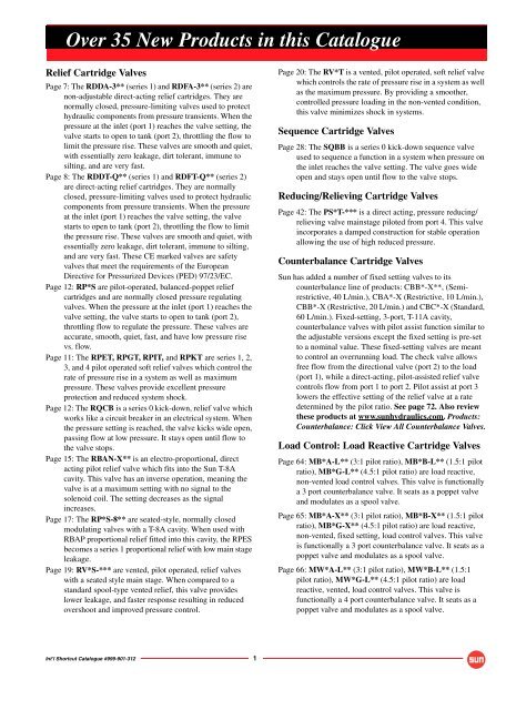
Over 35 New Products in this <strong>Catalog</strong>ueRelief Cartridge ValvesPage 7: The RDDA-3** (series 1) and RDFA-3** (series 2) arenon-adjustable direct-acting relief cartridges. They arenormally closed, pressure-limiting valves used to protecthydraulic components from pressure transients. When thepressure at the inlet (port 1) reaches the valve setting, thevalve starts to open to tank (port 2), throttling the flow tolimit the pressure rise. These valves are smooth and quiet,with essentially zero leakage, dirt tolerant, immune tosilting, and are very fast.Page 8: The RDDT-Q** (series 1) and RDFT-Q** (series 2)are direct-acting relief cartridges. They are normallyclosed, pressure-limiting valves used to protect hydrauliccomponents from pressure transients. When the pressureat the inlet (port 1) reaches the valve setting, the valvestarts to open to tank (port 2), throttling the flow to limitthe pressure rise. These valves are smooth and quiet, withessentially zero leakage, dirt tolerant, immune to silting,and are very fast. These CE marked valves are safetyvalves that meet the requirements of the EuropeanDirective for Pressurized Devices (PED) 97/23/EC.Page 12: RP*S are pilot-operated, balanced-poppet reliefcartridges and are normally closed pressure regulatingvalves. When the pressure at the inlet (port 1) reaches thevalve setting, the valve starts to open to tank (port 2),throttling flow to regulate the pressure. These valves areaccurate, smooth, quiet, fast, and have low pressure risevs. flow.Page 11: The RPET, RPGT, RPIT, and RPKT are series 1, 2,3, and 4 pilot operated soft relief valves which control therate of pressure rise in a system as well as maximumpressure. These valves provide excellent pressureprotection and reduced system shock.Page 12: The RQCB is a series 0 kick-down, relief valve whichworks like a circuit breaker in an electrical system. Whenthe pressure setting is reached, the valve kicks wide open,passing flow at low pressure. It stays open until flow tothe valve stops.Page 15: The RBAN-X** is an electro-proportional, directacting pilot relief valve which fits into the <strong>Sun</strong> T-8Acavity. This valve has an inverse operation, meaning thevalve is at a maximum setting with no signal to thesolenoid coil. The setting decreases as the signalincreases.Page 17: The RP*S-8** are seated-style, normally closedmodulating valves with a T-8A cavity. When used withRBAP proportional relief fitted into this cavity, the RPESbecomes a series 1 proportional relief with low main stageleakage.Page 19: RV*S-*** are vented, pilot operated, relief valveswith a seated style main stage. When compared to astandard spool-type vented relief, this valve provideslower leakage, and faster response resulting in reducedovershoot and improved pressure control.Page 20: The RV*T is a vented, pilot operated, soft relief valvewhich controls the rate of pressure rise in a system as wellas the maximum pressure. By providing a smoother,controlled pressure loading in the non-vented condition,this valve minimizes shock in systems.Sequence Cartridge ValvesPage 28: The SQBB is a series 0 kick-down sequence valveused to sequence a function in a system when pressure onthe inlet reaches the valve setting. The valve goes wideopen and stays open until flow to the valve stops.Reducing/Relieving Cartridge ValvesPage 42: The PS*T-*** is a direct acting, pressure reducing/relieving valve mainstage piloted from port 4. This valveincorporates a damped construction for stable operationallowing the use of high reduced pressure.Counterbalance Cartridge Valves<strong>Sun</strong> has added a number of fixed setting valves to itscounterbalance line of products: CBB*-X**, (Semirestrictive,40 L/min.), CBA*-X (Restrictive, 10 L/min.),CBB*-X (Restrictive, 20 L/min.) and CBC*-X (Standard,60 L/min.). Fixed-setting, 3-port, T-11A cavity,counterbalance valves with pilot assist function similar tothe adjustable versions except the fixed setting is pre-setto a nominal value. These fixed-setting valves are meantto control an overrunning load. The check valve allowsfree flow from the directional valve (port 2) to the load(port 1), while a direct-acting, pilot-assisted relief valvecontrols flow from port 1 to port 2. Pilot assist at port 3lowers the effective setting of the relief valve at a ratedetermined by the pilot ratio. See page 72. Also reviewthese products at www.sunhydraulics.com. Products:Counterbalance: Click View All Counterbalance Valves.Load Control: Load Reactive Cartridge ValvesPage 64: MB*A-L** (3:1 pilot ratio), MB*B-L** (1.5:1 pilotratio), MB*G-L** (4.5:1 pilot ratio) are load reactive,non-vented load control valves. This valve is functionallya 3 port counterbalance valve. It seats as a poppet valveand modulates as a spool valve.Page 65: MB*A-X** (3:1 pilot ratio), MB*B-X** (1.5:1 pilotratio), MB*G-X** (4.5:1 pilot ratio) are load reactive,non-vented, fixed setting, load control valves. This valveis functionally a 3 port counterbalance valve. It seats as apoppet valve and modulates as a spool valve.Page 66: MW*A-L** (3:1 pilot ratio), MW*B-L** (1.5:1pilot ratio), MW*G-L** (4.5:1 pilot ratio) are loadreactive, vented, load control valves. This valve isfunctionally a 4 port counterbalance valve. It seats as apoppet valve and modulates as a spool valve.Int’l Shortcut <strong>Catalog</strong>ue #999-901-312 1
Over 35 New Products in this <strong>Catalog</strong>ueLoad Control: Load Reactive Cartridge Valves(Continued)Page 67: MW*A-X** (3:1 pilot ratio), MW*B-X** (1.5:1pilot ratio), MW*G-X** (4.5:1 pilot ratio) are loadreactive, vented, load control valves. This valve isfunctionally a 4 port counterbalance valve. It seats as apoppet valve and modulates as a spool valve.Load Control: Balanced Cartridge ValvesPage 70: The MB*M-X** is a balanced, non-vented, nonrelievingload control valve. This valve displayscharacteristics of a pressure compensating flow controlvalve. Performance is best in the meter-out mode withport 1 being the load and port 2 being tank.Page 71: The MW*M-X** is a vented, balanced non-relieving,load control valves that combines a balanced modulatingelement with a reverse flow check. This valve displayscharacteristics of a pressure compensating flow controlvalve. Performance is best in the meter-out mode withport 1 being the load and port 2 being tank.Check Cartridge ValvesPage 74: CXAA-XB* is a free flow, nose-to-side, check valvewhich fits into T-8A cavity.Logic Element Cartridge ValvesPage 110: LO*C-ZD* is a balanced poppet, pilot-to-close,spring biased closed, logic element with positionindicating switch.Page 111: LO*O-ZD* is a balanced poppet, pilot-to-close,spring biased open, logic element with position indicatingswitch.Page 116: The LH*A-X** is a bypass/restrictive, prioritymodulating element.Solenoid Operated Cartridge ValvesPage 132: The DTDA-S** is a 2-position, 2-way directoperating poppet-type directional solenoid valve with softshift armature.Page 133: The DAAL-S** is a 2-position, 2-way, spool-typepilot solenoid valve with soft shift armature.Page 134: The DLDA-S** is a 2-position, 2-way spool-typedirectional solenoid valve with soft shift armature.Page 135: The DWDA-X** is a 2-position, 3-way poppet-typedirectional solenoid valve.Page 136: The DBAL-S** is a 2-position, 3-way, spool-typepilot solenoid valve with soft shift armature.Page 137: The DMDA-S** is a 2-position, 3-way spool-typedirectional solenoid valve with soft shift armature.Page 138: The DNDA-S** is a 2-position, 4-way spool-typedirectional solenoid valve with soft shift armature.Page 139: The DNDC-X** is a direct acting, solenoid-operated,4-way, 3-position spool valve that is spring centred to theneutral position.Pilot Control Cartridge ValvesPage 146: DAAL-X** is a 2-way, solenoid operated,directional spool-type, pilot valve.Page 146: DAAL-S** is a 2-position, 2-way, spool-type pilotsolenoid valve with soft shift armature.Page 150: The DBAL-X** is a 3-way, 2-position, solenoidoperated, directional spool-type, pilot valve.Page 150: DBAL-S** is a 3-way, 2-position, solenoid operated,directional spool-type pilot valve with soft shift armature.Corrosion Resistant Cartridge Valves<strong>Sun</strong> is continually adding to its line of corrosion resistantvalves. These valve have stainless steel and titaniumexternal components with heat treated internalcomponents in carbon and alloy steels. These valves arerecommended for marine, oil and gas industries and foruse in stationary aero-drives. All external components arequalified by a 1,000 hour salt spray test to ASTM B117-03. In all cases, the internal working components remainthe same as the standard <strong>Sun</strong> valve. Where the cartridgeproduct is offered in corrosion resistant materials, youwill see a note in the bottom right corner of the page. Visitwww.sunhydraulics.com for complete information onour Corrosion Resistant Cartridges. Products:Cartridges: Corrosion Resistant: View All CorrosionResistant Cartridges for complete information aboutthese cartridges.Weatherized Coils and Weatherized Coil KitsPage 190, 191: <strong>Sun</strong>’s new weatherized coils and kits aredesigned for <strong>Sun</strong>’s full flow solenoid operated andelectro-proportional cartridge valves. They are protectionagainst high-pressure wash-downs or marineenvironments for <strong>Sun</strong>’s electrically-actuated cartridgevalves. These coil kits are only available with theMetri-Pack Series 150-2M connector with a choice offour voltages.A weatherization kit is required in conjunction with aweatherized coil and a modified cavity (consult the <strong>Sun</strong>website to view cavity modification instructions for theuse of each kit). The coil is not included in the kits andmust be purchased separately. Weatherization kits arecartridge model code and cavity dependant. These kitsare intended for new installations only and are notsuitable for retrofitting existing equipment or forstandard <strong>Sun</strong> bodies.Consult www.sunhydraulics.com for complete details onweatherized coils and weatherized coil kits. Go toProducts: Cartridges: Coils: View All Coils: WeatherizedCoils. View individual Weatherized Coil Seal Kit page fordetailed installation instructions.2 Int’l Shortcut <strong>Catalog</strong>ue #999-901-312
ContentsModel Codes printed in Red are Preferred Versions of Products shown in this catalogue and most readily available.Relief Cartridge Valves . . . . . . . . . . . . . . . . . . . . . . . . . . . . . . . . 5Sequence Cartridge Valves . . . . . . . . . . . . . . . . . . . . . . . . . . . . 25Reducing and Reducing/Relieving. . . . . . . . . . . . . . . . . . . . . 33Cartridge ValvesPilot-to-Open Check Cartridge Valves . . . . . . . . . . . . . . . . . 47Counterbalance Cartridge Valves. . . . . . . . . . . . . . . . . . . . . . 51Load Control: Reactive Cartridge Valves . . . . . . . . . . . . . . 63Load Control: Balanced Cartridge Valves . . . . . . . . . . . . . 69Check Cartridge Valves . . . . . . . . . . . . . . . . . . . . . . . . . . . . . . . . 73Flow Control Cartridge Valves . . . . . . . . . . . . . . . . . . . . . . . . . 79Flow Divider / Combiner Cartridge Valves . . . . . . . . . . . . . 93Logic Elements . . . . . . . . . . . . . . . . . . . . . . . . . . . . . . . . . . . . . . . . 99Directional Cartridge Valves . . . . . . . . . . . . . . . . . . . . . . . . . . . 117Solenoid Operated Cartridge Valves. . . . . . . . . . . . . . . . . . . 131Pilot Control Cartridge Valves . . . . . . . . . . . . . . . . . . . . . . . . . 141Shuttle Cartridge Valves. . . . . . . . . . . . . . . . . . . . . . . . . . . . . . . 155Circuit Savers. . . . . . . . . . . . . . . . . . . . . . . . . . . . . . . . . . . . . . . . . . 163Hybrid Relief Cartridge Valves . . . . . . . . . . . . . . . . . . . . . . . . 171General Information . . . . . . . . . . . . . . . . . . . . . . . . . . . . . . . . . . . 177Cartridge Control Options . . . . . . . . . . . . . . . . . . . . . . . . . . . . . . . . . 178Cartridge Control Kits . . . . . . . . . . . . . . . . . . . . . . . . . . . . . . . . . . . . 179Cavity Plugs . . . . . . . . . . . . . . . . . . . . . . . . . . . . . . . . . . . . . . . . . . . . 183<strong>Sun</strong> Coil Options for Solenoids (Metal Housing, Round) . . . . . . . . . 187<strong>Sun</strong> Coil Options with Embedded Electronic. . . . . . . . . . . . . . . . . . . 188Proportional Amplifiers<strong>Sun</strong> Weatherized Coils and Coil Kits . . . . . . . . . . . . . . . . . . . . . . . . . 190<strong>Sun</strong> Coil 790-***** Part Numbering System . . . . . . . . . . . . . . . . . . 191Orifice Pressure Drop Data. . . . . . . . . . . . . . . . . . . . . . . . . . . . . . . . . 192<strong>Sun</strong> Model Code System . . . . . . . . . . . . . . . . . . . . . . . . . . . . . . 193<strong>Sun</strong> Model Code Index. . . . . . . . . . . . . . . . . . . . . . . . . . . . . . . . . 194Warranty . . . . . . . . . . . . . . . . . . . . . . . . . . . . . . . . . . . . . . . . . . . . . . . 199International Distribution . . . . . . . . . . . . . . . . . . . . . . . . . . . . . . 200Int’l Shortcut <strong>Catalog</strong>ue #999-901-312 3
Specifications, descriptions and illustrative material contained herein were accurate as known at thetime this publication was approved for printing.<strong>Sun</strong> <strong>Hydraulics</strong> reserves the right to discontinue models at any time, or change prices, specificationsor designs without notice or incurring obligation.All rights reserved. This book, or any part thereof, may not be reproduced or transmitted in any formor by any means, electronic or mechanical, including photocopying, recording,or information storage and retrieval systems, for any purposewithout the express written permission of <strong>Sun</strong> <strong>Hydraulics</strong> Corporation,1500 West University Parkway, Sarasota, Florida, 34243, USA.Copyright © 2009 <strong>Sun</strong> <strong>Hydraulics</strong> CorporationSarasota, FL 34243 USAPrinted in the United States of America4 Int’l Shortcut <strong>Catalog</strong>ue #999-901-312
Relief Cartridge ValvesCartridge TypePage2 1Pilot Operated, Balanced Piston 621Direct Acting and Direct Acting, Non-Adjustable 721Direct Acting, CE Marked 821Direct Acting, Pilot Capacity 92 1Pilot Operated, Balanced Poppet 102 1Pilot Operated, Balanced Poppet, Soft 112 1Pilot Operated, Kick-down, Balanced Piston 12Air Pilot21Pilot Operated, Balanced Piston, Air Controlled 132 1Electro-Proportional, Pilot Capacity 142 1Electro-Proportional, Pilot Capacity, High Pressure Settingwith No Command, Inverse Function152T-8ACav1Pilot Operated, Balanced Piston, Main Stagewith Integral T-8A Control Cavity162T-8ACav1Pilot Operated, Balanced Poppet, Main Stagewith Integral T-8A Control Cavity1732 1Pilot Operated, Balanced Piston, Ventable 1832 1Pilot Operated, Balanced Poppet, Ventable 1932 1Pilot Operated, Balanced Poppet, Ventable, Soft 20231Bypass Compensator with Relief Function,Normally Closed21432 134 T-8ACav21Pilot Operated, Balanced Piston, Ventablewith External DrainElectro-Proportional, Pilot Operated,Balanced Piston, Ventable, Drain to Port 4,Main Stage with Integral T-8A Control Cavity2223Int’l Shortcut <strong>Catalog</strong>ue #999-901-312 5
Relief ValvesPILOT OPERATED, BALANCED PISTONFull Adjustment 5 Turns+ -bc2 12OutletInlet1Performance CurvesaLocatingShoulderCapacityTypicalCartridgeModel CodeCartridge DimensionscCavity a bL C KRPCC RPEC RPGC RPIC RPKCTypical Pressure RiseP = bar350300250200150100500 25 50 75 100Flow = L/min.P = bar35030025020015010050■Maximum operating pressure = 350 bar.■Maximum valve leakage at 24 cSt = RPCC, RPEC: 30 cc/min. at 70 bar; RPGC: 50 cc/min. at 70 bar;RPIC: 65,5 cc/min. at 70 bar; RPKC: 80 cc/min. at 70 bar.■Typical response time 10 ms.■Factory pressure settings established at 15 L/min.■Will accept maximum pressure at Port 2.■Back pressure on the tank port (port 2) is directly additive at a 1:1 ratio to the valve setting.RP ✱ C – ✱ ✱ ✱NominalCapacityControl** Adjustment Range Seal MaterialC 45 L/min. L Standard Screw RPCC only: N Buna-NAdjustment A 5 - 210 barE 95 L/min. Standard set at 70 bar V VitonC* Tamper Resistant B 5 - 105 barG 200 L/min. Factory Set Standard set at 70 barC 5 - 420 barI 380 L/min. K Handknob Standard set at 70 barwith Lock Knob N 5 - 55 barK 760 L/min. Standard set at 30 barRPEC,Q 5 - 25 barRPGC only:Standard set at 14 barO Handknob withW 5 - 315 barPanel MountStandard set at 70 bar* Special setting required. RPEC, RPGC,Specify at time of order.RPIC, RPKC only:A 7 - 210 barStandard set at 70 barB 3,5 - 105 barStandard set at 70 barC 10,5 - 420 bar** See page 178 Standard set at 70 barfor information N 4 - 55 baron Control OptionsStandard set at 28 barQ 4 - 25 barCustomer specifiedStandard set at 14 barspecial settingW 10,5 - 315 barstamped on hex.Standard set at 70 barVisit www.sunhydraulics.com for current list pricing and complete technical information on all <strong>Sun</strong> products.InstallationTorque(Nm)45 L/min. RPCC – LAN T - 162A 31,0 19,1 53,6 55,1 60,7 35 - 4095 L/min. RPEC – LAN T - 10A 39,6 22,2 50,8 54,6 57,2 45 - 50200 L/min. RPGC – LAN T-3A 47,8 28,6 53,8 55,4 60,5 60 - 70380 L/min. RPIC – LAN T - 16A 62,0 31,8 62,0 62,7 68,3 200 - 215760 L/min. RPKC – LAN T-18A 79,5 41,3 71,4 74,7 77,7 465 - 50050 100 150Flow = L/min.OPTION ORDERING INFORMATION0200P = bar350300250200150100500100 200 300Flow = L/min.400P = bar350300250200150100500200 400 600Flow = L/min.800P = bar350300250200150100500400 800 1200 1600Flow = L/min.Consult the <strong>Sun</strong> website forour most recent and completeinformation on the full CorrosionResistant line of products.6 Int’l Shortcut <strong>Catalog</strong>ue #999-901-312
Relief ValvesDIRECT ACTING AND DIRECT ACTING, NON-ADJUSTABLEFull Adjustment 5 Turns+ -L Control3 Control21bcRD*A2OutletInlet1aPerformance CurvesLocatingShoulderCapacityTypicalCartridgeModel CodeCartridge DimensionscCavity a bL CInstallationTorque(Nm)45 L/min. RDBA – LAN T - 162A 31,0 19,1 53,6 56,4 35 - 4095 L/min. RDDA – LAN T - 10A 39,6 22,2 59,2 63,2 45 - 50200 L/min. RDFA – LAN T-3A 47,8 28,6 63,5 65,0 60 - 70380 L/min. RDHA – LAN T - 16A 62,0 31,8 82,6 84,1 200 - 215760 L/min. RDJA – LAN T - 18A 79,5 41,3 100,0 103,4 465 - 500RDBA RDDA RDFA RDHA RDJATypical Pressure RiseP = bar35030025020015010050P = bar35030025020015010050P = bar35030025020015010050P = bar35030025020015010050P = bar35030025020015010050010 20 30 40 500 25 50 75 100Flow = L/min.Flow = L/min.050 100 150Flow = L/min.■ Maximum operating pressure = 350 bar.■ Maximum valve leakage at reseat = 0,7 cc/min.■ Typical response time 2 ms.■ Factory pressure settings established at 15 L/min.■ Will accept maximum pressure at Port 2.■ Back pressure on the tank port (port 2) is directly additive at a 1:1 ratio to the valve setting.■ The seals on the adjust screw are exposed to system pressure which means this valve can only be adjusted whenthe pressure is removed. The setting procedure is; check the setting, remove the pressure, adjust the valve, check the new setting.■ Reseat exceeds 90% of cracking pressure.■ Select a spring range where the desired relief setting is approximately mid-range between the minimum and maximum pressureto ensure maximum valve repeatability.OPTION ORDERING INFORMATION200RD ✱ A – ✱ ✱ ✱0100 200 300Flow = L/min.4000200 400 600Flow = L/min.800NominalCapacityControl** Adjustment Range Seal MaterialB 45 L/min. L Standard Screw A 35 - 210 bar N Buna-NAdjustmentStandard set at 70 barD 95 L/min. B 20 - 105 bar V VitonC*Tamper ResistantStandard set at 70 barF 200 L/min. Factory Set C 70 - 420 barStandard set at 70 barH 380 L/min. RDDA, RDFA only: D 14 - 55 bar3* Non-Adjustable Standard set at 28 barJ 760 L/min. E 10 - 28 bar* Special setting required. Standard set at 14 barSpecify at time of order. S 3,5 - 14 barStandard set at 7 barW 55 - 315 barStandard set at 70 bar** See page 178for informationRDDA-3, RDFA-3on Control Optionsonly available withA, C, D ranges.Consult the <strong>Sun</strong> websitefor our most recent andCustomer specifiedcomplete informationU.S. Patent #4,742,846 special settingon the full CorrosionEuropean Patent Pending stamped on hex.Resistant line of products.Visit www.sunhydraulics.com for current list pricing and complete technical information on all <strong>Sun</strong> products.Int’l Shortcut <strong>Catalog</strong>ue #999-901-312 7
Relief ValvesDIRECT ACTING, CE MARKEDFull Adjustment 5 Turns+ -c21The CE marked valve is a safety valve that meets the requirements of the EuropeanDirective for Pressurized Devices (PED) 97/23/EC.Each delivery contains a TüV approval, which is a certification of the excessoperating pressure and the approved flow, an EC declaration of conformity, and aninstructional manual. See <strong>Sun</strong> website for further information.b2OutletaLocatingShoulderCapacity75 L/min.TypicalCartridgeModel CodeCartridge DimensionsCavity a b cInstallationTorque(Nm)RDDT – QAN T-10A 40,0 mm 22,2 mm 65,0 mm 45 - 501InletPerformance Curves79 L/min.RDFT – QAN T - 3A 47,8 mm 28,6 mm 70,4 mm 60 - 70RDDTRDFTPermissible Operating Range■■■■■■■P = bar450400350300250200150PermissibleRange*450400350300250200150100PermissibleRange100500 20 40 60 800 20 40 60 80 100Flow = L/min.Flow = L/min.Maximum Approved FlowMaximum Approved Flow*Approved flow at 210 bar is 75 L/min.P = barMaximum valve leakage at reseat = 0,7 cc/min.Reseat = > 90% of set pressure.Typical response time 2 ms.Standard settings for preset valves: 100, 140, 160, 210, 250, and 330 bar.Pressure setting from 100 bar up to 422 bar are approved and certified by TüV.Will accept maximum pressure at port 2; suitable for use in cross-port relief circuits.Back pressure on the tank port (port 2) is additive to the valve setting at a 1:1 ratio.OPTION ORDERING INFORMATIONRD ✱ T– ✱ ✱ ✱NominalCapacityControl Adjustment Range Seal MaterialD 75 L/min. Q*Capped and RDDT: N Buna-NLockwireA 100 - 210 barV VitonF 79 L/min. * Special setting required.Specify at time of order.C 315 - 422 barW 211 - 314 barRDFT:A 106 - 209 barB 60 - 105 barC 210 - 420 barU.S. Patent #4,742,846Visit www.sunhydraulics.com for current list pricing and complete technical information on all <strong>Sun</strong> products.8 Int’l Shortcut <strong>Catalog</strong>ue #999-901-312
Relief ValvesDIRECT ACTING, PILOT CAPACITYFull Adjustment 5 Turns+ -21bca2OutletInlet 1Performance CurvesLocatingShoulderCapacityTypicalCartridgeModel CodeCavity a bCartridge DimensionscL C K OInstallationTorque(Nm)1 L/min. RBAC – LAN T - 10A 39,6 22,2 50,8 54,6 57,2 58,0 45 - 502 L/min. RBAA – LAN T - 3A 47,8 28,6 53,8 55,4 60,5 61,0 60 - 7010 L/min. RBAE – LAN T-8A 19,0 22,2 60,5 62,7 67,6 67,6 35 - 40RBAC RBAA RBAE■■■■■P = bar350300250200150100500 0,32 0,64 0,96 1,28 1,6Flow = L/min.P = barTypical Pressure Rise350300250200150100500 0,5 1,0 1,5 2,0 2,5Flow = L/min.Maximum operating pressure = 350 bar.Maximum valve leakage at reseat at 24 cSt = RBAC, RBAA: 0,4 cc/min.; RBAE: 1 cc/min.Typical response time 2 ms.Back pressure on the tank port (port 2) is directly additive to the pressure settingat port 1 (inlet) at a 1:1 ratio to the valve setting.RBAE: Utilizes the <strong>Sun</strong> T-8A, 2 port cavity making it the ideal choice to use in conjunction with <strong>Sun</strong>’smain stage pilot or vent-to-operate cartridges. Separate pilot lines are eliminated and only one cavityneeds to be machined to accommodate both the control and primary function. Note: All 2-position,2-way pilot stage control cartridges utilize the same cavity and are physically interchangeable.Functionality is the only consideration.P = bar4003002001000 2 4 6 8 10Flow = L/min.OPTION ORDERING INFORMATIONRB A ✱ – ✱ ✱ ✱NominalCapacityControl** Adjustment Range Seal MaterialAC 1 L/min. L Standard Screw A 1,7 - 210 bar N Buna-NAdjustmentStandard set at 70 barV VitonAA 2 L/min. C*Tamper Resistant B 1,7 - 105 barwith Lock KnobStandard set at 70 barAE 10 L/min. K Handknob C 1,7 - 420 barFactory SetStandard set at 70 barO Handknob withPanel MountD 1,7 - 55 barStandard set at 25 bar* Special setting required. E 1,7 - 25 barSpecify at time of order. Standard set at 14 bar** See page 178 W 1,7 - 315 barfor informationStandard set at 70 baron Control OptionsCustomer specified specialsetting stamped on hex.Visit www.sunhydraulics.com for current list pricing and complete technical information on all <strong>Sun</strong> products.Consult the <strong>Sun</strong> website forour most recent and completeinformation on the full CorrosionResistant line of products.Int’l Shortcut <strong>Catalog</strong>ue #999-901-312 9
Relief ValvesPILOT OPERATED, BALANCED POPPETFull Adjustment 5 Turns+ -2 1bc2OutletInlet 1aPerformance CurvesLocatingShoulderCapacityTypicalCartridgeModel CodeCavity a bCartridge DimensionscL C KInstallationTorque(Nm)95 L/min. RPES – LAN T-10A 39,6 22,2 50,8 54,6 57,2 40 - 50200 L/min. RPGS – LAN T - 3A 47,8 28,6 53,8 55,4 60,5 60 - 70380 L/min. RPIS – LAN T-16A 62,0 31,8 62,0 62,7 68,3 200 - 215760 L/min. RPKS – LAN T - 18A 79,5 41,3 71,4 74,7 77,7 465 - 500RPES RPGS RPIS RPKSTypical Pressure RiseP = bar25020015010050P = bar25020015010050P = bar25020015010050P = bar250200150100500■■■■■■25 50 75Flow = L/min.OPTION ORDERING INFORMATION95050 100 150Flow = L/min.200100 200 300Flow = L/min.Maximum operating pressure = 350 bar.Maximum valve leakage at reseat = RPES: 0,7 cc/min.; RPGS, RPIS, RPKS: 2,1 cc/min.Typical response time 2 ms.Factory pressure settings established at 15 L/min.Will accept maximum pressure at port 2; suitable for use in cross-port relief circuits.Back pressure on the tank port (port 2) is directly additive at a 1:1 ratio to the valve setting.RP ✱ S – ✱ ✱ ✱04000 200 400 600Flow = L/min.800NominalCapacityControl** Adjustment Range Seal MaterialE 95 L/min. C* Tamper Resistant A 7 - 210 bar N Buna-NFactory SetStandard set at 70 barG 200 L/min.K Handknob B 3,5 - 105 bar V VitonI 380 L/min. with Lock Knob Standard set at 70 barK 760 L/ min. L Standard Screw C 10,5 - 420 barAdjustmentStandard set at 70 bar* Special setting required. N 4 - 55 barSpecify at time of order. Standard set at 30 barQ 4 - 25 barStandard set at 14 barRPES, RPGS only:W 7 - 315 barStandard set at 70 bar** See page 178 RPIS, RPKS only:for informationW 10,5 - 315 baron Control OptionsStandard set at 70 barCustomer specified specialsetting stamped on hex.Consult the <strong>Sun</strong> website forour most recent and completeinformation on the full CorrosionResistant line of products.Visit www.sunhydraulics.com for current list pricing and complete technical information on all <strong>Sun</strong> products.10 Int’l Shortcut <strong>Catalog</strong>ue #999-901-312
Relief ValvesPILOT OPERATED, BALANCED POPPET, SOFTFull Adjustment 4.5 Turns+ -bc2 1212Outlet1InletaLocatingShoulderSimplified SymbolCapacityTypicalCartridgeModel CodeComplex SymbolCavity a bCartridge DimensionscPerformance CurvesRPET RPGT RPIT RPKT400LCInstallationTorque(Nm)95 L/min. RPET - LAN T-10A 39,6 22,8 79,5 85,1 40 - 50200 L/min. RPGT - LAN T - 3A 47,8 28,6 85,9 88,1 60 - 70380 L/min. RPIT - LAN T-16A 61,7 31,8 86,9 89,2 200 - 215760 L/min. RPKT - LAN T - 18A 79,2 41,3 88,4 85,3 465 - 500400Pressure Differential vs. Flow400400P = bar300200100P = bar300200100P = bar300200100P = bar3002001000 25 50 75Flow = L/min.100050 100 150Flow = L/min.2000 100 200 300Flow = L/min.4000 200 400 600Flow = L/min.800Time vs. Pressure400400400400P = bar300200100P = bar300200100P = bar300200100P = bar3002001000 250 500 750 1000Time/ms.■Maximum operating pressure = 350 bar.■Control pilot flow = 0,16 to 0,41 L/min.■Pressure Ramp Up Time = RPET: 200 ms., RPGT: 300 ms., RPIT: 400 ms., RPIC: 500 ms.■Factory pressure settings established at 15 L/min.■Will accept maximum pressure at Port 2.■When pressure at the inlet (port 1) exceeds the threshold setting, the valve opens to tank (port 2). Thepilot section moves forward at a steady rate, increasing the setting by compressing the pilot spring.Maximum setting is achieved when the pilot section reaches a mechanical stop.OPTION ORDERING INFORMATIONRP ✱ T– ✱ ✱ ✱NominalCapacityControl** Adjustment Range Seal MaterialE 95 L/min. C*Tamper Resistant A 140 - 210 bar N Buna-NFactory SetStandard set at 140 barG 200 L/min. V VitonL Standard Screw C 315 - 420 barI 380 L/min. Adjustment Standard set at 315 barK 760 L/min. * Special setting required. W 210-315 barSpecify at time of order. Standard set at 210 barPatent:U.S. #6,039,070.0 200 400 600 800Time/ms.** See page 178for informationon Control Options1000Customer specified specialsetting stamped on hex.0 250 500 750 1000Time/ms.Visit www.sunhydraulics.com for current list pricing and complete technical information on all <strong>Sun</strong> products.0 250 500 750 1000Time/ms.Int’l Shortcut <strong>Catalog</strong>ue #999-901-312 11
Relief ValvesPILOT OPERATED, KICK-DOWN, BALANCED PISTONFull Adjustment 5 Turns+ -b2OutletInlet1caLocatingShoulder2 1CapacityTypicalCartridgeModel CodeCavity a bCartridge DimensionscL C KInstallationTorque(Nm)45 L/min. RQCB – LAN T - 162A 31,0 19,1 53,6 55,1 58,7 35 - 4095 L/min. RQEB – LAN T - 10A 39,6 22,2 50,8 54,6 57,2 45 - 50200 L/min. RQGB– LAN T-3A 47,8 28,6 53,8 55,4 60,5 60 - 70380 L/min. RQIB – LAN T - 16A 62,0 31,8 62,0 62,7 68,3 200 - 215760 L/min. RQKB – LAN T - 18A 79,5 41,3 71,4 74,7 77,7 465 - 500Performance CurvesRQCB RQEB RQGB RQIB RQKBP = bar2015105A,B,C,N,Q,W0 20 40 60Flow = L/min.■■■■■■P = bar2015105C & WAB,N,Q0 25 50 75 100Flow = L/min.P = barUnloaded Pressure Drop201510C & W5 AB,N,Q0 50 100 150 200Flow = L/min.0 100 200 300 400Flow = L/min.Maximum operating pressure = 350 bar.Maximum valve leakage at 24 cSt = RQCB, RQEB: 30 cc/min. at 70 bar;RQGB: 49,2 cc/min. at 70 bar; RQIB: 65,5 cc/min. at 70 bar; RQKB: 81,9 cc/min. at 70 bar.Typical response time 25 ms.Factory pressure settings established at kick down point.Flow through cartridge must cease to reset valve.Back pressure on the tank port (port 2) is directly additive to the valve setting at a 1:1 ratio.P = bar2015105AC & WB,N,QP = bar2015105C & WAB,N,Q0 200 400 600 800Flow = L/min.OPTION ORDERING INFORMATIONRQ ✱ B – ✱ ✱ ✱NominalCapacityControl** Adjustment Range Seal MaterialC 45 L/min. L Standard Screw RQCB only: N Buna-NAdjustmentA 5 - 210 barE 95 L/min. Standard set at 70 bar V VitonC* Tamper Resistant B 5 - 105 barG 200 L/min. Factory Set Standard set at 70 barC 5 - 420 barI 380 L/min. K Handknob Standard set at 70 barwith Lock KnobN 5 - 55 barK 760 L/min. Standard set at 25 bar* Special setting required. Q 5 - 25 barSpecify at time of order.Standard set at 14 barW 5 - 315 barStandard set at 70 barRQEB, RQGB,RQIB, RQKB only:A 7 - 210 barStandard set at 70 barB 3,5 - 105 barStandard set at 70 barC 10,5 - 420 barStandard set at 70 bar** See page 178 Q 4 - 25 barfor informationStandard set at 14 baron Control OptionsW 10,5 - 315 barStandard set at 70 bar Consult the <strong>Sun</strong> website forCustomer specifiedRQEB, RQGB, only: our most recent and completespecial settingN 4 - 55 barinformation on the full Corrosionstamped on hex.Standard set at 25 bar Resistant line of products.Visit www.sunhydraulics.com for current list pricing and complete technical information on all <strong>Sun</strong> products.12 Int’l Shortcut <strong>Catalog</strong>ue #999-901-312
Relief ValvesPILOT OPERATED, BALANCED PISTON, AIR CONTROLLEDAir Pilot PortAir Pilotbc21LocatingShoulder2OutletaCapacityTypicalCartridgeModel CodeCartridge DimensionscCavity a bABInstallationTorque(Nm)200 L/min. RPGD – ABN T-3A 47,8 28,6 33,3 — 60 - 70380 L/min. RPID – BBN T - 16A 62,0 31,8 — 41,1 200 - 215760 L/min. RPKD – BBN T-18A 79,5 41,3 — 50,8 465 - 500Inlet1Performance CurvesRPGD RPID RPKDTypical Pressure RiseP = bar20015010050P = bar20015010050P = bar200150100500 50 100 150 200Flow = L/min.0 100 200 300 400Flow = L/min.0 200 400 600 800Flow = L/min.■Pilot ratio, air to hydraulic = 20:1.■Maximum air pressure = 10,5 bar.■Maximum operating pressure = 140 bar.■Maximum valve leakage at 24 cSt = RPGD: 50 cc/min. at 70 bar; RPID: 65 cc/min. at 70 bar;RPKD: 80 cc/min. at 70 bar.■Typical response time 10 ms.■Will accept maximum pressure at Port 2; suitable for use in cross-port relief circuits.OPTION ORDERING INFORMATIONRP ✱ D – ✱ ✱ ✱NominalCapacityControl Adjustment Range Seal MaterialRPGD only:RPGD only:G 200 L/min. A External B 3,5 - 105 bar N Buna-N1/4" NPTFI 380 L/min. Pilot Port at I 1 - 70 bar V Vitonend of Cartridge*K 760 L/min. RPID, RPKD only:RPID, RPKD only: B 3,5 - 105 barB External SAE-4Pilot Port atRPKD only:end of Cartridge* J 2 - 105 bar* Maximum air pilot pressureshould not exceed 10 bar.Visit www.sunhydraulics.com for current list pricing and complete technical information on all <strong>Sun</strong> products.Int’l Shortcut <strong>Catalog</strong>ue #999-901-312 13
Relief Valves, Electro-ProportionalELECTRO-PROPORTIONAL, PILOT CAPACITYd2 1cb2OutletInlet 1LocatingShoulderPerformance CurvesaCapacityTypicalCartridgeModel CodeRBAPCartridge DimensionsCavity a b c*** dInstallationTorque(Nm)L/T X/M1 L/min. RBAP – X** T-8A 18,8 22,2 130,0 85,1 37,3 35 - 40***An additional 50,8 mm clearance is needed for coil installation and removal.300Constant CommandVarying FlowPressure vs. CommandFlow 0,37 L/min.300P = bar200100P = bar2001000.50 1.00 1.50Flow = L/min.2.00■ Maximum operating pressure = 350 bar.■ Maximum valve leakage at reseat = 25 cc/min.■ Hysteresis with dither
Relief Valves, Electro-ProportionalELECTRO-PROPORTIONAL, PILOT CAPACITY, HIGH PRESSURE SETTINGWITH NO COMMAND, INVERSE FUNCTIONd2 1cCapacityTypicalCartridgeModel CodeCartridge DimensionsCavity a b c*** dInstallationTorque(Nm)1 L/min. RBAN – XAN T-8A 18,8 22,2 108,2 37,3 35 - 40b***An additional 50,8 mm clearance is needed for coil installation and removal.2OutletaLocatingShoulder1InletPerformance Curves300RBANPressure Differentialvs. Flow300Pressurevs. CommandP = bar200100A SpringP = bar200100A Spring01 2 3L/min.■ Maximum operating pressure = 350 bar.■ Maximum valve leakage at reseat = 25 cc/min.■ Hysteresis with dither
Relief Valves, Electro-ProportionalPILOT OPERATED, BALANCED PISTON, MAIN STAGE WITH INTEGRALT-8A CONTROL CAVITYT-8ACavT-8A Cavity 21The -8 control option allows a pilot control valve to be incorporated directlyinto the end of the relief cartridge via the T-8A cavity. These pilot controlcartridges are sold separately and include electro-proportional, solenoid, airpilot, and hydraulic pilot operation. See Pilot Control Cartridges on page 141.bcLocatingShoulder2OutletInlet 1aCapacityTypicalCartridgeModel CodeCartridge DimensionsCavity a b cInstallationTorque(Nm)95 L/min. RPEC – 8WN T-10A 39,6 22,2 19,0 45 - 50200 L/min. RPGC – 8WN T - 3A 47,8 28,6 17,5 60 - 70380 L/min. RPIC – 8WN T-16A 62,0 31,8 24,6 200 - 215760 L/min. RPKC – 8WN T - 18A 79,5 41,3 30,2 465 - 500Performance CurvesRPEC-8 RPGC-8 RPIC-8 RPKC-8400Pressure vs. Flow with T-8A Pilot Stage Installed400400400P = bar300200100P = bar300200100P = bar300200100P = bar300200100P = bar02502001501005020 40 60 80Flow = L/min.100 0 40 80 120 160 200 0 80 160 240 320 400 0 160 320 480 640 800Flow = L/min.Flow = L/min.Flow = L/min.Pressure vs. Command with T-8A Pilot Stage (RBAP-MAN) InstalledP = bar25020015010050P = bar25020015010050P = bar25020015010050020 40 60 80Command (%)■■■■■■100 0 20 40 60 80Command (%)100 0 20 40 60 80Command (%)20 40 60 80Command (%)Maximum operating pressure = 350 bar.Control pilot flow = RPEC-8: 0,11 to 0,16 L/min.; RPGC-8: 0,16 to 0,25 L/min.;RPIC-8, RPKC-8: 0,25 to 0,33 L/min.Main stage leakage at 24 cSt = RPEC-8: 50 cc/min. at 70 bar; RPGC-8: 50 cc/min. at 70 bar;RPIC-8: 65 cc/min. at 70 bar; RPKC-8: 80 cc/min. at 70 bar.Will accept maximum pressure at Port 2; suitable for use in cross-port relief circuits.Back pressure on the tank port (port 2) is directly additive to the valve setting at a 1:1 ratio.With the -8 control option, the main stage valve should first be installed to the correct torque value.The T-8A pilot control valve should then be installed into the main stage valve to its required torque value.1000100OPTION ORDERING INFORMATIONRP ✱ C – 8 ✱✱NominalMinimum ControlControlCapacityPressureSeal MaterialE 95 L/min. 8 T-8A Cavity in D 1,7 bar N Buna-Nhex body forG 200 L/min. pilot operation W 7 bar V VitonI 380 L/min.Pilot valve tobe orderedK 760 L/min.separatelyVisit www.sunhydraulics.com for current list pricing and complete technical information on all <strong>Sun</strong> products.16 Int’l Shortcut <strong>Catalog</strong>ue #999-901-312
Relief Valves, Electro-ProportionalPILOT OPERATED, BALANCED POPPET, MAIN STAGE WITH INTEGRALT-8A CONTROL CAVITYT-8A Cavity2T-8ACav1The -8 control option allows a pilot control valve to be incorporated directlyinto the end of the relief cartridge via the T-8A cavity. These pilot controlcartridges are sold separately and include electro-proportional, solenoid, airpilot, and hydraulic pilot operation. See Pilot Control Cartridges on page 141.bcLocatingShoulder2OutletInlet 1aCapacityTypicalCartridgeModel CodeCartridge DimensionsCavity a b cInstallationTorque(Nm)95 L/min. RPES – 8WN T - 10A 39,6 22,2 19,0 40 - 50200 L/min. RPGS – 8WN T - 3A 47,8 28,6 17,5 60 - 70380 L/min. RPIS – 8WN T - 16A 62,0 31,8 24,6 200 - 215760 L/min. RPKS – 8WN T - 18A 79,2 41,3 30,0 465 - 500Performance CurvesRPES-8 RPGS-8 RPIS-8 RPKS-8P = bar25020015010050Pressure Differential vs. Flow with T-8A Pilot Stage InstalledP = bar25020015010050P = bar25020015010050P = bar25020015010050P = bar02502001501005025 50 75Flow = L/min.100Pressure vs. Command with T-8A Pilot Stage (RBAP-MAN) InstalledP = bar25020015010050050 100 150Flow = L/min.200P = bar250200150100500100 200 300Flow = L/min.400P = bar250200150100500 200 400 600Flow = L/min.800020 40 60 80Command (%)■■■■■■■100 0 20 40 60 80Command (%)100 0 20 40 60 80Command (%)20 40 60 80Command (%)Maximum operating pressure = 350 bar.Control pilot flow = RPES-8: 0,16 to 0,41 L/min.; RPGS-8: 0,16 to 0,25 L/min.;RPIS-8, RPKS-8: 0,25 to 0,33 L/min.Main stage leakage at 10% reseat = 0,7 cc/min.Typical response time 2 ms.Will accept maximum pressure at Port 2; suitable for use in cross-port relief circuits.Back pressure on the tank port (port 2) is directly additive to the valve setting at a 1:1 ratio.With the -8 control option, the main stage valve should first be installed to the correct torque value.The T-8A pilot control valve should then be installed into the main stage valve to its required torque value.1000100OPTION ORDERING INFORMATIONRP ✱ S – 8 ✱✱NominalMinimum ControlControlCapacityPressureSeal MaterialE 95 L/min. 8 T-8A Cavity in B 3,5 bar N Buna-Nhex body forG 200 L/min. pilot operation W 7 bar V VitonPilot valve toI 380 L/min.be orderedRPES-8 only:separatelyD 1,7 barK 760 L/min.Visit www.sunhydraulics.com for current list pricing and complete technical information on all <strong>Sun</strong> products.Int’l Shortcut <strong>Catalog</strong>ue #999-901-312 17
Relief ValvesPILOT OPERATED, BALANCED PISTON, VENTABLEFull Adjustment 5 Turns+ -2 13bcPerformance CurvesRVBA RVCA RVEA RVGA RVIAP = bar■■■■■■■■3Vent2Outlet350300250200150100500Inlet 1a10 20 30 40Flow = L/min.LocatingShoulder50P = bar350300CapacityTypicalCartridgeModel CodeMaximum operating pressure = 350 bar.Maximum valve leakage at 24 cSt = RVBA, RVCA: 30 cc/min. at 70 bar; RVEA: 50 cc/min. at 70 bar;RVGA: 65 cc/min. at 70 bar; RVIA: 80 cc/min. at 70 bar.Typical response time 10 ms.Control pilot flow = RVBA, RVCA: 0,11 to 0,16 L/min.; RVEA: 0,16 to 0,25 L/min.; RVGA, RVIA: 0,25 to 0,33 L/min.Factory pressure setting established at 15 L/min.A remote pilot relief on port 3 (vent) will control the valve below its own setting.Will accept maximum pressure at port 2; suitable for use in cross-port relief circuits. If used in cross-port relief circuits, considerspool leakage.Back pressure on the tank port (port 2) is directly additive to the valve setting at a 1:1 ratio.RV ✱ A – ✱ ✱ ✱NominalCapacityControl** Adjustment Range Seal MaterialB 30 L/min. L Standard Screw RVBA only: N Buna-NAdjustmentA 5 - 210 barC 60 L/min. Standard set at 70 bar V VitonC*Tamper ResistantB 5 - 105 barE 120 L/min. Factory Set Standard set at 70 bar Consult the <strong>Sun</strong> website forC 5 - 420 barour most recent and completeG 240 L/min. K Handknob Standard set at 70 bar information on the full Corrosionwith Lock Knob N 5 - 55 bar Resistant line of products.I 480 L/min. Standard set at 28 barRVCA, RVEA only: Q 5 - 25 barO Handknob withStandard set at 14 barPanel MountW 5 - 315 barStandard set at 70 bar*Special setting required.Specify at time of order.Cavity a bRVCA, RVEA, RVGA,RVIA only:A 7 - 210 barStandard set at 70 barB 3,5 - 105 barStandard set at 70 barCartridge Dimensions** See page 178 C 10 - 420 bar Adjustment Ranges (Continued)for information Standard set at 70 bar RVEA, RVIA only:on Control Options D 1,7 - 55 bar N 4 - 55 barStandard set at 28 bar Standard set at 28 barE 1,7 - 28 barCustomer specified Standard set at 14 bar RVEA only:special setting W 10 - 315 bar Q 4 - 28 barstamped on hex. Standard set at 70 bar Standard set at 14 barVisit www.sunhydraulics.com for current list pricing and complete technical information on all <strong>Sun</strong> products.cL C K OInstallationTorque(Nm)30 L/min. RVBA – LAN T - 163A 31,0 19,1 64,8 66,8 70,4 71,0 35 - 4060 L/min. RVCA – LAN T - 11A 35,1 22,2 63,5 67,3 70,0 70,0 45 - 50120 L/min. RVEA – LAN T-2A 34,8 28,6 71,4 73,2 77,7 — 60 - 70240 L/min. RVGA – LAN T - 17A 46,0 31,8 83,3 84,1 89,7 — 200 - 215480 L/min. RVIA – LAN T-19A 63,5 41,3 100,0 103,9 106,4 — 465 - 500250200150100500 25 50 75 100Flow = L/min.OPTION ORDERING INFORMATIONP = bar350300250200150100500Typical Pressure Rise50 100 150Flow = L/min.200P = bar350300250200150100500100 200 300Flow = L/min.400P = bar350300250200150100500200 400 600Flow = L/min.80018 Int’l Shortcut <strong>Catalog</strong>ue #999-901-312
Relief ValvesPILOT OPERATED, BALANCED POPPET, VENTABLEFull Adjustment 5 Turns+ -2 13bc3Vent2OutletInlet 1Performance CurvesRVCSP = barP = bar35030025020015010050201510500aLocatingShoulder20 40 60 80Flow = L/min.A,C,WB,Q,N20 40 60Flow = L/min.CapacityTypicalCartridgeModel Code■ Maximum operating pressure = 350 bar.■ Maximum valve leakage at 90% reseat = RVCS: 2 cc/min at 70 bar.; RVES, RVGS, RVIS: 0,7 cc/min at 70 bar.■ Typical response 2 ms.■ Control pilot flow = RVCS: 0,11 to 0,16 L/min.; RVES, RVIS, RVGS: 0,25 to 0,33 L/min.■ Factory pressure setting established at 15 L/min.■ Will accept maximum pressure at port 2; suitable for use in cross-port relief circuits.■ A remote pilot relief on port 3 (vent) will control the valve below its own setting.■ Back pressure on the tank port (port 2) is directly additive to the valve setting at a 1:1 ratio.RV ✱ S – ✱ ✱ ✱NominalCapacityControl** Adjustment Range Seal MaterialC 60 L/min. C*Tamper Resistant A 7 - 210 bar N Buna-NFactory SetStandard set at 70 barE 95 L/min. V VitonK Handknob B 3,5 - 105 barG 200 L/min. with Lock Knob Standard set at 70 barI 480 L/min. L Standard Screw C 10,5 - 420 barAdjustmentStandard set at 70 bar* Special setting required. N 4 - 55 barSpecify at time of order.Standard set at 25 bar** See page 178 Q 4 - 25 barfor informationStandard set at 14 baron Control OptionsW 10,5 - 315 barCustomer specified specialStandard set at 70 barsetting stamped on hex.Cartridge DimensionscCavity a bL C KVisit www.sunhydraulics.com for current list pricing and complete technical information on all <strong>Sun</strong> products.InstallationTorque(Nm)60 L/min. RVCS – LAN T-11A 34,8 22,2 63,2 67,3 70,0 45 - 5095 L/min. RVES – LAN T - 2A 34,8 28,6 71,4 73,2 77,7 60 - 70200 L/min. RVGS – LAN T-17A 46,0 31,8 83,3 84,1 89,7 200 - 215480 L/min. RVIS – LAN T - 19A 63,5 41,3 99,8 103,1 106,4 465 - 500RVES10080P = barP = bar350350300 30025020015010050OPTION ORDERING INFORMATION2015050 100 150Flow = L/min.RVGSTypical Pressure Rise20010C,W5B,N,Q A0 25 50 75 100 125 150Flow = L/min.P = barP = bar25020015010050Vented Pressure020151050100 200 300Flow = L/min.C,W,AB,Q,N80 160 240Flow = L/min.RVIS400320P = barP = bar35030025020015010050201510500A100 200 300 400Flow = L/min.BQ & NC & W100 200 300 400Flow = L/min.500500Int’l Shortcut <strong>Catalog</strong>ue #999-901-312 19
Relief ValvesPILOT OPERATED, BALANCED POPPET, VENTABLE, SOFTFull Adjustment 4.5 Turns+ -3bc2 1321LocatingShoulderSimplified SymbolCapacityTypicalCartridgeModel CodeComplex SymbolCartridge DimensionsCavity a bLcCInstallationTorque(Nm)2Outlet1InletPerformance Curvesa120 L/min. RVET – LAN T-2A 35,1 28,6 110,2 113,5 60 - 70240 L/min. RVGT – LAN T - 17A 46,0 31,8 114,3 116,8 200 - 215480 L/min. RVIT – LAN T-19A 63,5 35,1 115,6 120,1 465 - 500RVET RVGT RVITPressure vs. Flow - A Spring Range Shown300300300P = bar200100P = bar200100P = bar20010020025 50 75 100Flow = L/min.1250 50 100 150 200 2500 100 200 300 400 500Flow = L/min.Flow = L/min.Vented Pressure vs. Flow2020P = bar15105A,W,CBP = bar15105A,B,C,WP = bar15105A,B,C,W■■■■■■■0 25 50 75 100Flow = L/min.125050 100 150Flow = L/min. 2002500100 200 300 400 500Flow = L/min.Maximum operating pressure = 350 bar.Control pilot flow = RVET: 0,16 to 0,41 L/min.; RVGT, RVIT: 0,25 to 0,33 L/min.Pressure ramp up time = RVET: 300 ms.; RVGT: 400 ms.; RVIT: 500 ms.Typical response time 2 ms.Factory pressure setting established at 15 L/min.Will accept maximum pressure at port 2; suitable for use in cross-port relief circuits.A remote pilot relief on port 3 (vent) will control the valve below its own setting.OPTION ORDERING INFORMATIONRV ✱ T– ✱ ✱ ✱NominalCapacityControl** Adjustment Range Seal MaterialE 120 L/min. C* Tamper Resistant A 35 - 210 bar N Buna-NFactory SetStandard set at 70 barG 240 L/min. L Standard Screw B 35 - 105 barV VitonAdjustmentStandard set at 70 barI 480 L/min. * Special setting required. C 70 - 420 barSpecify at time of order. Standard set at 70 bar** See page 178 W 70 - 315 barfor informationStandard set at 70 baron Control OptionsCustomer specified specialsetting stamped on hex.Visit www.sunhydraulics.com for current list pricing and complete technical information on all <strong>Sun</strong> products.20 Int’l Shortcut <strong>Catalog</strong>ue #999-901-312
Relief ValvesBYPASS COMPENSATOR WITH RELIEF FUNCTION, NORMALLY CLOSEDFull Adjustment 5 Turns+ -3bc213Sense2BypassInletPerformance Curves1aLocatingShoulderCapacityTypicalCartridgeModel CodeCavity a bCartridge DimensionscL C KInstallationTorque(Nm)20 L/min. RVBB – LAN T - 163A 30,7 19,1 64,5 66,8 70,4 35 - 4040 L/min. RVCB – LAN T - 11A 35,1 22,2 63,5 65,3 69,3 45 - 5080 L/min. RVEB – LAN T-2A 35,1 28,6 71,4 73,2 77,7 60 - 70160 L/min. RVGB – LAN T - 17A 46,0 31,8 83,3 84,1 89,7 200 - 215320 L/min. RVIB – LAN T-19A 63,8 41,3 100,0 103,1 105,9 465 - 500RVBB RVCB RVEB RVGB RVIBThe X axis of the performance curves shown indicates the system pressure. The Y axis of the performance curves indicates the pressure differentialthat the valve creates across the control orifice. The curves represent various bypass flows (pump flow minus control flow). The capacities listed andperformance of these valves are determined by the bypass flow. The control flow is not a factor.P = bar20151050■■■■■■60 L/min.20 L/min.40 L/min.50 100 150 200Bypass Flow = barP = bar20151050120 L/min.40 L/min.80 L/min.50 100 150 200Bypass Flow = barP = bar2015105050 100 150 200Bypass Flow = barMaximum operating pressure = 350 bar.Maximum valve leakage at 24 cSt = RVBB, RVCB: 30 cc/min. at 70 bar; RVEB: 50 cc/min. at 70 bar;RVGB: 65 cc/min. at 70 bar; RVIB: 80 cc/min. at 70 bar.Typical response time 10 ms.Factory pressure setting established at 15 L/min.Back pressure on the tank port (port 2) is directly additive to the valve setting at a 1:1 ratio.Compensating pressure for all ranges is 8 bar.OPTION ORDERING INFORMATIONTypical Compensator Differentials240 L/min.80 L/min.160 L/min.RV ✱ B – ✱ ✱ ✱NominalCapacityControl** Adjustment Range Seal MaterialB 20 L/min. L Standard Screw RVBB only: N Buna-NAdjustmentA 5 - 210 barC 40 L/min. Standard set at 70 bar V VitonC*Tamper ResistantB 5 - 105 barE 80 L/min. Factory Set Standard set at 70 bar Consult the <strong>Sun</strong> website forC 5 - 420 barour most recent and completeG 160 L/min. K Handknob Standard set at 70 bar information on the full Corrosionwith Lock Knob N 5 - 55 bar Resistant line of products.I 320 L/min. Standard set at 30 bar* Special setting required. Q 5 - 25 barSpecify at time of order. Standard set at 14 barW 5 - 315 barStandard set at 70 barAdjustment Ranges (Continued)RVCB, RVEB,RVCB, RVGB, RVIB only:** See page 178 RVGB, RVIB only: B 3,5 - 105 barfor information A 7 - 210 bar Standard set at 70 baron Control Options Standard set at 70 bar RVCB, bias pressure is 4 bar.C 10,5 - 420 barCustomer specified Standard set at 70 bar RVCB, RVEB only:special setting D 2 - 55 bar W 7 - 315 barstamped on hex. Standard set at 30 bar Standard set at 70 barVisit www.sunhydraulics.com for current list pricing and complete technical information on all <strong>Sun</strong> products.P = bar20151050480 L/min.240 L/min.320 L/min.50 100 150 200Bypass Flow = barP = bar20151050560 L/min.480 L/min.320 L/min. 380 L/min.50 100 150 200Bypass Flow = barInt’l Shortcut <strong>Catalog</strong>ue #999-901-312 21
Relief ValvesPILOT OPERATED, BALANCED PISTON, VENTABLE WITH EXTERNAL DRAINFull Adjustment 5 Turns+ -bc42 134Drain3Vent2OutletInlet1P = bar35030025020015010050aLocatingShoulderCapacityTypicalCartridgeModel CodeCavity a bCartridge DimensionscL C KInstallationTorque(Nm)60 L/min. RVCD – LAN T - 21A 35,1 22,2 78,5 82,6 84,8 45 - 50120 L/min. RVED – LAN T - 22A 35,1 28,6 87,4 89,0 93,7 60 - 70240 L/min. RVGD – LAN T - 23A 46,0 31,8 99,8 101,3 106,4 200 - 215480 L/min. RVID – LAN T - 24A 63,5 41,8 121,4 126,7 127,8 465 - 500Performance CurvesRVCD RVED RVGD RVIDP = bar35030025020015010050Typical Pressure RiseP = bar35030025020015010050P = bar35030025020015010050150 50 100 150 200Flow = L/min.150 100 200 300 400Flow = L/min.Vented Pressure150 200 400 600 800Flow = L/min.150 400 800 1200 1600Flow = L/min.P = bar1050AB D & E■■■■■■■C & W20 40 60Flow = L/min.80P = bar1050ABC & WD & E40 80 120Flow = L/min.160P = bar1050ABD & E100 200 300Flow = L/min.Maximum operating pressure = 350 bar.Maximum valve leakage at 24 cSt = RVCD: 30 cc/min. at 70 bar; RVED: 50 cc/min. at 70 bar;RVGD: 65 cc/min. at 70 bar; RVID: 80 cc/min. at 70 bar.Control pilot flow = RVCD: 0,11 to 0,16 L/min.; RVED: 0,16 to 0,25 L/min.; RVGD, RVID: 0,25 to 0,33 L/min.Typical response time 10 ms.Factory pressure setting established at 15 L/min.Pressure at port 4 is directly additive to the valve setting at a 1:1 ratio and should not exceed 350 bar.Will accept maximum pressure at port 2; suitable for use in cross-port relief circuits.C & W400P = bar1050AD & EC & WB200 400 600Flow = L/min.800OPTION ORDERING INFORMATIONRV ✱ D – ✱ ✱ ✱NominalCapacityControl** Adjustment Range Seal MaterialC 60 L/min. L Standard Screw A 7 - 210 bar N Buna-NAdjustmentStandard set at 70 barE 120 L/min. C* Tamper Resistant B 3,5 - 105 barV VitonFactory SetStandard set at 70 barG 240 L/min. K Handknob C 10,5 - 420 barwith Lock KnobStandard set at 70 barI 480 L/min. * Special setting required. D 1,7 - 55 barSpecify at time of order.Standard set at 30 bar** See page 178 E 1,7 - 28 barfor informationStandard set at 14 baron Control OptionsW 10,5 - 315 barCustomer specified specialStandard set at 70 barsetting stamped on hex.Visit www.sunhydraulics.com for current list pricing and complete technical information on all <strong>Sun</strong> products.22 Int’l Shortcut <strong>Catalog</strong>ue #999-901-312
Relief Valves, Electro-ProportionalPILOT OPERATED, BALANCED PISTON, VENTABLE, DRAIN TO PORT 4,MAIN STAGE WITH INTEGRAL T-8A CONTROL CAVITYbT-8A Cavity34 T-8ACav21The -8 control option allows a pilot control valve to be incorporated directlyinto the end of the relief cartridge via the T-8A cavity. These pilot controlcartridges are sold separately and include electro-proportional, solenoid, airpilot, and hydraulic pilot operation. See Pilot Control Cartridges on page 141.4Drainc3Vent2OutletInlet 1Performance Curves400aLocatingShoulderCapacityTypicalCartridgeModel CodeCartridge DimensionsCavity a b cInstallationTorque(Nm)60 L/min. RVCD – 8WN T - 21A 35,1 22,2 45,2 45 - 50120 L/min. RVED – 8WN T - 22A 35,1 28,6 50,8 60 - 70240 L/min. RVGD – 8WN T - 23A 46,0 31,8 65,8 200 - 215480 L/min. RVID – 8WN T - 24A 63,5 41,3 80,3 465 - 500RVCD-8 RVED-8 RVGD-8 RVID-8400Pressure vs. Flow400400P = bar300200100P = bar300200100P = bar300200100P = bar300200100020 40 60Flow = L/min.80040 80 120Flow = L/min.160080 160 240Flow = L/min.3200160 320 480Flow = L/min.640P = bar151050W■■■■■■Pressure vs. Command with T-8A Pilot Stage (RBAP-MAN) InstalledP = bar1510W5DD20 40 60 800 40 80 120 1600Flow = L/min.Flow = L/min.P = bar151055D100 200 300 4000Flow = L/min.WD200 400 600 800Flow = L/min.Maximum operating pressure = 350 bar.Main stage leakage at 24 cSt = RVCD-8: 30 cc/min. at 70 bar; RVED-8: 50 cc/min. at 70 bar;RVGD-8: 65 cc/min. at 70 bar; RVID-8: 80 cc/min. at 70 bar.Control pilot flow = RVCD-8: 0,11 to 0,16 L/min.; RVED-8: 0,16 to 0,25 L/min.; RVGD-8,RVID-8: 0,25 to 0,33 L/min.Typical response time 10 ms.Will accept maximum pressure at port 2; suitable for use in cross-port relief circuits.Pressure at port 4 is directly additive to the valve setting at a 1:1 ratio and should not exceed 350 bar.WP = bar1510OPTION ORDERING INFORMATIONRV ✱ D – 8 ✱✱NominalMinimum ControlCapacityControlPressureSeal MaterialC 60 L/min. 8 T-8A Cavity in D 1,7 bar N Buna-Nhex body forE 120 L/min. pilot operation W 7 bar V VitonGI240 L/min.480 L/min.Pilot valve tobe orderedseparatelyVisit www.sunhydraulics.com for current list pricing and complete technical information on all <strong>Sun</strong> products.Int’l Shortcut <strong>Catalog</strong>ue #999-901-312 23
Protection against pressure spikes. . .NEW SOFT SHIFT OPTIONFOR SUN RELIEF CARTRIDGE VALVESUsing these newly designed pressure relief valves, pressures can be ramped up and ramped down. These reliefvalves work purely mechanically, and protect hydraulic components against pressure spikes that could damagemachinery. Soft shift relief valves are available as pure pressure relief valves and as ventable relief valvesin different frame sizes. As cartridge valves they can be used in many different types of assemblies such assandwich, line mount, gasket mount, and custom.Benefits of <strong>Sun</strong>’s Soft ReliefControlled rate of pressure rise means lessdynamic stress for components.No pressure transients above setting.Limited rate of force change.Increases the life expectancy of hoses andother critical components in the circuit.Uses a normally open pilot section to maintaina minimum threshold setting.A minimum threshold setting allows thevalve to begin controlling the rate ofpressure rise immediately from the ventpressure setting.Incorporates a return spring to ensurea reliable reset.See catalogue pages 11 (RP*T) and 20 (RV*T) fordetailed information on relief cartridges with softshift options.Soft Shift option extended to <strong>Sun</strong> Solenoid Operated Directional Valves. . .<strong>Sun</strong>’s small pilot solenoid valves are used to unload larger main-stage elements remotely, or by directly integrating the pilot valveinto the main-stage element. In this latter approach, unique to <strong>Sun</strong>, 12 different pilot valves (proportional, solenoid, hydraulic andpneumatic) can be integrated into a variety of main-stage elements.Most 2-position, 2-way screw-in cartridge pilot solenoid valves utilize a poppet style construction to satisfy low leakagerequirements. <strong>Sun</strong> <strong>Hydraulics</strong> has adopted a different approach that utilizes a precision spool/sleeve design. Available in both2-position, 2- and 3-way pilot solenoid cartridges, this approach produces leakage characteristics equivalent to poppet style designs.Since control volumes in pilot circuits are typically small, the lower gain characteristics of spool valves produce a softer unload. Tofurther extend the operating rate, <strong>Sun</strong> offers a soft shift option that adds an orifice in the valve’s armature to gain greater control of fluiddisplacement. Combining the benefits of a spool valve with the soft shift option extends shift times, which can reduce the hydraulicshock generated when unloading main-stage elements. <strong>Sun</strong>’s Soft Shift option is offered on all of its spool-type solenoid valves.You will find additional information about the DTDA-S, DAAL-S, DLDA-S, DBAL-S, DMDA-S, DNDA-S on pages 132 through 138in the Solenoid section of this catalogue.Consult the <strong>Sun</strong> websitew w w. sunhydr aulic s.c o mfor detailed and complete information on <strong>Sun</strong> soft shift options.Products: Cartridges: Relief: View All Relief Cartridges and Products: Cartridges: Solenoids: View all Solenoid Operated Cartridges.Products: Cartridges: Solenoid Operated: View All Solenoid Operated Cartridges24Int’l Shortcut <strong>Catalog</strong>ue #999-901-312
Sequence Cartridge ValvesCartridge TypePage32 1Pilot Operated, Balanced Piston 26231Direct Acting with Reverse Flow Check 2732 1Kick-down, Pilot Operated, Balanced Piston 2832 1Air Controlled, Pilot Operated, Balanced Piston 29231Direct Acting without Reverse Flow Check 3032T-8ACav1Electro-Proportional, Pilot Operated,Balanced Piston, Main Stage withIntegral T-8A Control Cavity31Int’l Shortcut <strong>Catalog</strong>ue #999-901-312 25
Sequence ValvesPILOT OPERATED, BALANCED PISTONFull Adjustment 5 Turns+ -32 1bc3Drain2SequenceInlet1aLocatingShoulderCapacityTypicalCartridgeModel CodeCartridge DimensionscCavity a bL C KPerformance CurvesRSBC RSDC RSFC RSHC RSJCP = bar1412108642010 20 30Flow = L/min.40P = bar14121086420InstallationTorque(Nm)30 L/min. RSBC – LAN T - 163A 31,0 19,1 64,8 66,8 70,4 35 - 4060 L/min. RSDC – LAN T - 11A 35,1 22,2 63,5 67,3 70,0 45 - 50120 L/min. RSFC – LAN T - 2A 35,1 28,6 71,4 73,2 77,7 60 - 70240 L/min. RSHC – LAN T - 17A 46,0 31,8 83,3 84,1 89,7 200 - 215480 L/min. RSJC – LAN T - 19A 63,5 41,3 100,0 103,9 106,4 465 - 50020 40 60Flow = L/min.80Pressure Drop Fully SequencedP = bar1412108642040 80 120Flow = L/min.160P = bar1412108642Pilot Flow after Valve Sequence for RS*CFlow = L/min.1.000.750.500.25080 160 240Flow = L/min.320P = bar14121086420160 320 480Flow = L/min.640■Maximum operating pressure = .350 bar.■Maximum valve leakage at 24 cSt = RSBC,RSDC: 30 cc/min. at 70 bar; RSFC: 50 cc/min. at 70 bar;RSHC: 65 cc/min. at 70 bar; RSJC: 80 cc/min. at 70 bar.■Typical response time 10 ms.0 50 100 150 200 250 300 350P = bar■Pressure at port 3 is directly additive to the valve setting at a 1:1 ratioand should not exceed 350 bar.■Pilot flow continues to increase as the pressure at port 1 (inlet),relative to the pressure at port 3 (drain), rises above the valve setting.OPTION ORDERING INFORMATIONRS ✱ C – ✱ ✱ ✱NominalCapacityControl** Adjustment Range Seal MaterialB 30 L/min. L Standard Screw RSBC only: N Buna-NAdjustmentA 5 - 210 barD 60 L/min. Standard set at 70 bar V VitonC*Tamper ResistantB 5 - 105 barF 120 L/min. Factory Set Standard set at 70 bar Consult the <strong>Sun</strong> website forC 5 - 420 barour most recent and completeH 240 L/min. K Handknob Standard set at 70 bar information on the full Corrosionwith Lock Knob N 5 - 55 bar Resistant line of products.J 480 L/min. Standard set at 28 bar* Special setting required. Q 5 - 28 barSpecify at time of order. Standard set at 14 barW 5 - 315 barStandard set at 70 barRSDC, RSFC, RSHC,RSJC only:Adjustment Ranges (Continued)A 7 - 210 bar** See page 178 Standard set at 70 bar RSDC, RSFC, RSHC only:for information B 3,5 - 105 bar N 4 - 55 baron Control Options Standard set at 70 bar Standard set at 28 barC 10 - 420 barCustomer specified Standard set at 70 bar RSDC, RSFC, RSJC only:special setting W 10 - 315 bar Q 4 - 28 barstamped on hex. Standard set at 70 bar Standard set at 14 barVisit www.sunhydraulics.com for current list pricing and complete technical information on all <strong>Sun</strong> products.26 Int’l Shortcut <strong>Catalog</strong>ue #999-901-312
Sequence ValvesDIRECT ACTING WITH REVERSE FLOW CHECKFull Adjustment 4 Turns+-321bc3Drain2SequenceInlet1aLocatingShoulderCapacityTypicalCartridgeModel CodeCartridge DimensionscCavity a bLCInstallationTorque(Nm)60 L/min. SCCA – LAN T - 11A 35,1 22,2 78,5 80,0 45 - 50120 L/min. SCEA – LAN T - 2A 35,1 28,6 88,1 89,7 60 - 70240 L/min. SCGA – LAN T - 17A 46,0 31,8 100,0 101,6 200 - 215480 L/min. SCIA – LAN T - 19A 63,5 41,3 122,9 128,5 465 - 500Performance CurvesSCCA SCEA SCGA SCIAP = bar20151050Free FlowFullySequenced15 30 45Flow = L/min.60P = bar2015105Free Flow to Pressure Drop Fully Sequenced0Free FlowFullySequenced30 60 90 120Flow = L/min.P = bar20151050Free FlowFullySequencedP = bar2015105FullySequencedFree Flow60 120 180 240 0 120 240 360 480Flow = L/min.Flow = L/min.■■■■■■Maximum operating pressure = 350 bar.Maximum valve leakage at reseat = 0,7 cc/min.Reverse flow check cracking pressure = SCCA: 2,8 bar; SCEA: 1,7 bar; SCGA, SCIA: 1,5 bar.Typical response time 2 ms.Pressure at port 3 is directly additive to the valve setting at a 1:1 ratio and should not exceed 350 bar.Although this is a zero pilot flow valve, port 3 (drain) must be connected to maintain a pressurereference in the control chamber. If port 3 is blocked, reciprocating seal weepage will cause the valveto malfunction.OPTION ORDERING INFORMATIONSC ✱ A – ✱ ✱ ✱NominalCapacityControl** Adjustment Range Seal MaterialC 60 L/min. L Standard Screw A 35 - 210 bar N Buna-NAdjustmentStandard set at 70 barE 120 L/min. C* Tamper Resistant B 20 - 105 bar V VitonFactory SetStandard set at 70 barG 240 L/min. C 140 - 420 bar* Special setting required. Standard set at 140 barI 480 L/min.Specify at time of order.D 14 - 55 barStandard set at 28 barW 55 - 315 barStandard set at 70 bar** See page 178 SCCA only:for informationE 7 - 28 baron Control Options Standard set at 14 bar Consult the <strong>Sun</strong> website forour most recent and completeCustomer specified specialinformation on the full CorrosionU.S. Patent #4,834,135 setting stamped on hex. Resistant line of products.Visit www.sunhydraulics.com for current list pricing and complete technical information on all <strong>Sun</strong> products.Int’l Shortcut <strong>Catalog</strong>ue #999-901-312 27
Sequence ValvesKICK-DOWN, PILOT OPERATED, BALANCED PISTONFull Adjustment 5 Turns+ -32 1bc3Drain2SequenceInlet1Performance CurvesaLocatingShoulderCapacityTypicalCartridgeModel CodeCartridge DimensionscCavity a bL C KInstallationTorque(Nm)30 L/min. SQBB – LAN T - 163A 31,0 19,1 64,8 67,8 70,0 35 - 4060 L/min. SQDB – LAN T - 11A 35,1 22,2 63,5 65,0 70,0 40 - 50120 L/min. SQFB – LAN T - 2A 35,1 28,6 71,4 73,2 77,7 60 - 70240 L/min. SQHB – LAN T - 17A 46,0 31,8 83,3 84,1 89,7 200 - 215480 L/min. SQJB – LAN T - 19A 63,5 41,3 100,0 103,9 106,4 465 - 500SQBB SQDB SQFB SQHB SQJBPressure Drop After OpeningP = bar108642A,B,C,N,Q,WP = bar108642C & WABD & EP = bar108642BC & WAD & EP = bar20161284BC & WAD & EP = bar20161284BC & WAD & E015Flow = L/min.30■■■■0 15 30 45 600 30 60 90 1200 100 200 300 4000 200 400 600 800Flow = L/min.Flow = L/min.Flow = L/min.Flow = L/min.Maximum operating pressure = 350 bar.Maximum valve leakage at 24 cSt = SQBB, SQDB: = 30 cc/min. at 70 bar; SQFB: 50 cc/min. at 70 bar;SQHB: 65 cc/min. at 70 bar; SQJB: 80 cc/min. at 70 bar.Typical response time 25 ms.Pressure at port 3 is directly additive to the valve setting at a 1:1 ratio and should not exceed 350 bar.OPTION ORDERING INFORMATIONSQ ✱ B – ✱ ✱ ✱NominalCapacityControl** Adjustment Range Seal MaterialB 30 L/min. L Standard Screw SQBB only: N Buna-NAdjustmentA 5 - 210 barD 60 L/min. Standard set at 70 bar V VitonC* Tamper Resistant B 5 - 105 barF 120 L/min. Factory Set Standard set at 70 barC 5 - 420 barH 240 L/min. K Handknob Standard set at 70 barwith Lock KnobN 5 - 55 barJ 480 L/min. Standard set at 28 bar* Special setting required. Q 5 - 28 barSpecify at time of order. Standard set at 14 barW 5 - 315 barStandard set at 70 barSQDB, SQFB,SQHB, SQJB only:A 7 - 210 barStandard set at 70 barB 3,5 - 105 barStandard set at 70 barC 10,5 - 420 bar** See page 178 Standard set at 70 barfor informationD 1,7 - 55 baron Control OptionsStandard set at 28 barE 1,7 - 28 barConsult the <strong>Sun</strong> website forCustomer specified Standard set at 14 bar our most recent and completespecial setting W 10,5 - 315 bar information on the full Corrosionstamped on hex. Standard set at 70 bar Resistant line of products.Visit www.sunhydraulics.com for current list pricing and complete technical information on all <strong>Sun</strong> products.28 Int’l Shortcut <strong>Catalog</strong>ue #999-901-312
Sequence ValvesAIR CONTROLLED, PILOT OPERATED, BALANCED PISTONAir Pilot Port3bc2 13Drain2SequenceInlet1aLocatingShoulderCapacityTypicalCartridgeModel CodeCavity a bCartridge DimensionsAcBInstallationTorque(Nm)120 L/min. RSFE – ABN T - 2A 35,1 28,6 50,8 - 60 - 70240 L/min. RSHE – BBN T - 17A 46,0 31,8 - 62,7 200 - 215480 L/min. RSJE – BBN T - 19A 63,5 41,3 - 79,2 465 - 500Performance CurvesRSFE RSHE RSJEP = bar2821147Pressure Drop Fully SequencedP = bar2821147P = bar28211470 40 80 120 160Flow = L/min.0100 200 300Flow = L/min.4000200 400 600Flow = L/min.800Pilot Flow after Vavle SequenceFlow = L/min.1.000.750.500.25Flow = L/min.2.001.501.000.50Flow = L/min.2.001.501.000.500 50 100 150 200 250 300 3500 50 100 150 200 250 300 3500 50 100 150 200 250 300 350P = bar P = bar P = bar■Pilot ratio, air to hydraulic = 20:1.■Maximum operating pressure = 140 bar.■Maximum air pressure = 10 bar.■Maximum valve leakage at 24 cSt = RSFE: 50 cc/min. at 70 bar; RSHE: 65 cc/min. at 70 bar;RSJE: 80 cc/min. at 70 bar.■Typical response time 10 ms.OPTION ORDERING INFORMATIONRS ✱ E– ✱ B ✱NominalCapacityControl Adjustment Range Seal MaterialF 120 L/min. Available for RSFE only B 3,5 - 105 bar N Buna-NH 240 L/min. A External 1/4" NPTF V VitonPilot Port atJ 480 L/min. end of CartridgeRSHE, RSJE onlyB External SAE-4Pilot Port atend of CartridgeVisit www.sunhydraulics.com for current list pricing and complete technical information on all <strong>Sun</strong> products.Int’l Shortcut <strong>Catalog</strong>ue #999-901-312 29
Sequence ValvesDIRECT ACTING WITHOUT REVERSE FLOW CHECKFull Adjustment 4 Turns+ -321bc3Drain2SequenceaLocatingShoulderCapacityTypicalCartridgeModel CodeCartridge DimensionscCavity a bLCInstallationTorque(Nm)60 L/min. SXCA – LAN T - 11A 35,1 22,2 78,5 80,3 45 - 50120 L/min. SXEA – LAN T - 2A 35,1 28,6 88,1 89,9 60 - 70Inlet1Performance CurvesSXCASXEAPressure Drop Fully SequencedP = bar2821147P = bar80604020■■■■■0 20 40 60Flow = L/min.040 80 120 160Flow = L/min.Maximum operating pressure = 350 bar.Maximum valve leakage at reseat = 0,7 cc/min. Reseat exceeds 85% of cracking pressure.Typical response time 2 ms.Pressure at port 3 is directly additive to the valve setting at a 1:1 ratio and should not exceed 350 bar.Although this is a zero pilot flow valve, port 3 (drain) must be connected to maintain a pressurereference in the control chamber. If port 3 is blocked, reciprocating seal weepage will cause the valveto malfunction.200OPTION ORDERING INFORMATIONSX ✱ A – ✱ ✱ ✱NominalCapacityControl** Adjustment Range Seal MaterialC 60 L/min. L Standard Screw A 35 - 210 bar N Buna-NAdjustmentStandard set at 70 barE 120 L/min. V VitonC* Tamper Resistant B 20 - 105 barFactory SetStandard set at 70 bar* Special setting required. C 140 - 420 barSpecify at time of order. Standard set at 140 bar** See page 178for informationon Control OptionsD 14 - 55 barStandard set at 28 barW 55 - 315 barStandard set at 70 barConsult the <strong>Sun</strong> website forour most recent and completeU.S. Patent Customer specified special information on the full Corrosion#4,834,135. setting stamped on hex. Resistant line of products.Visit www.sunhydraulics.com for current list pricing and complete technical information on all <strong>Sun</strong> products.30 Int’l Shortcut <strong>Catalog</strong>ue #999-901-312
Sequence Valves, Electro-ProportionalPILOT OPERATED, BALANCED PISTON, MAIN STAGEWITH INTEGRAL T-8A CONTROL CAVITYb3Drain2SequenceT-8A CavityInlet 1caLocatingShoulder32T-8ACavCapacity1TypicalCartridgeModel CodeThe -8 control option allows a pilot control valve to be incorporated directlyinto the end of the modulating element via the T-8A cavity. These pilot controlcartridges are sold separately and include electro-proportional, solenoid, airpilot, and hydraulic pilot operation. See Pilot Control Cartridges on page 141.Cartridge DimensionsCavity a b cInstallationTorque(Nm)60 L/min. RSDC – 8WN T-11A 35,1 22,2 30,2 45 - 50120 L/min. RSFC – 8WN T - 2A 35,1 28,6 35,1 60 - 70240 L/min. RSHC – 8WN T-17A 46,0 31,8 46,0 200 - 215480 L/min. RSJC – 8WN T - 19A 63,5 41,3 58,7 465 - 500Performance CurvesRSDC-8 RSFC-8 RSHC-8 RSJC-8Typical Pressure vs. Flow with T-8A Pilot Stage (RBAP-MAN) Installed400400400400P = bar300200100P = bar300200100P = bar300200100P = bar300200100020 40 60Flow = L/min.80040 80 120Flow = L/min.160080 160 240Flow = L/min.3200160 320 480Flow = L/min.640Pressure vs. Command200200200200P = bar15010050P = bar15010050P = bar15010050P = bar15010050■■■■■■020 40 60 80Command (%)100020 40 60 80Command (%)10020 40 60 80Command (%)Maximum operating pressure = 350 bar.Main stage leakage at 24 cSt = RSDC-8: 30 cc/min. at 70 bar; RSFC-8: 50 cc/min. at 70 bar;RSHC-8: 65 cc/min. at 70 bar; RSJC-8: 80 cc/min. at 70 bar.Control pilot flow = RSDC-8: 0,11 to 0,16 L/min.; RSFC-8: 0,16 to 0,25 L/min.; RSHC-8, RSJC-8: 0,25 to 0,33 L/min.Will accept maximum pressure at Port 2; suitable for use in cross-port relief circuits. If used in cross-port reliefcircuits, consider spool leakage.Pressure at port 3 is directly additive at a 1:1 ratio to the valve setting and should not exceed 350 bar.With the -8 control option, the main stage valve should first be installed to the correct torque value. TheT-8A pilot control valve should then be installed into the main stage valve to its required torque value.0100020 40 60 80Command (%)100OPTION ORDERING INFORMATIONRS ✱ C – 8 ✱✱Nominal Control Minimum ControlCapacityPressureSeal MaterialD 60 L/min. 8 T-8A Cavity in D 1,7 bar N Buna-Nhex body forF 120 L/min. pilot operation W 7 bar V VitonHJ240 L/min.480 L/min.Pilot valve tobe orderedseparatelyVisit www.sunhydraulics.com for current list pricing and complete technical information on all <strong>Sun</strong> products.Int’l Shortcut <strong>Catalog</strong>ue #999-901-312 31
Differentiation in <strong>Sun</strong> Manifold DesignCUSTOM VALVE PACKAGES<strong>Sun</strong> <strong>Hydraulics</strong> manufactures custom engineered valve packages or “valvepaks” at all of itslocations around the world. Valvepaks are comprised of standard screw-in cartridge valves housed in acustom manifold. Once a customer’s hydraulic circuit has been developed, it is incorporated into a single,custom manifold designed to fit into a defined location.Benefits to customers:Creative and innovative manifold designusing solid modeling.Rapid response for prototypes.Let <strong>Sun</strong> design your manifold.Classic Three-Axis Straight Hole Drilling125 cubic inches (5 x 5 x 5)2,048 cubic centimetres (12,7 x 12,7 x 12,7)17 construction plugs.Utilizing <strong>Sun</strong> cartridges with our uniquefloating style cartridge construction.Compound angle drill for extremelycompact designs.Construction plugs are eliminatedor dramatically reduced.Larger and more efficient flow paths.Manifolds available in T-6061 (210 bar)aluminium and 65-45-12 high-strength(350 bar) SG iron.<strong>Sun</strong>’s Five-Axis Compound Angle Drilling64 cubic inches (4 x 4 x 4)1,049 cubic centimetres (10,2 x 10,2 x 10,2)0 construction plugs.View our full range of cartridge and manifold products on the <strong>Sun</strong> website:www.sunhydraulics.comProducts: Manifolds: Manifold SelectorProducts: Product SelectorOr select your cartridge first, then select a matching manifold from menu at the top of cartridge page32Int’l Shortcut <strong>Catalog</strong>ue #999-901-312
Reducing and Reducing/RelievingCartridge ValvesCartridge TypePage32 1Pilot Operated Reducing 34Air Pilot3Pilot Operated Reducing, Air Controlled 352 132T-8ACav1Pilot Operated Reducing, Main Stagewith Integral T-8A Control Cavity36321Pilot Operated Reducing/Relieving 37Air Pilot3Pilot Operated, Reducing/Relieving, Air Controlled 382 1321Direct Acting Reducing/Relieving 39432 1Pilot Operated Reducing/Relieving,Externally Drained to Port 440432 1Pilot Operated Reducing/Relieving, Ventable 411432Direct Acting Reducing/Relieving, Main Stage,Piloted from Port 4421Electro-Proportional, Direct Acting Reducing/Relieving,Open Transition, Improved Dynamic Response43213Electro-Proportional, Direct Acting Reducing/Relieving,Low Leakage44232T-8ACav31Pilot Operated Reducing/Relieving, Main Stage,with Integral T-8A Control Cavity452T-8ACav341Pilot Operated Reducing/Relieving, Main Stage,with Integral T-8A Control Cavity, Drain to Port 4,Externally Drained46Int’l Shortcut <strong>Catalog</strong>ue #999-901-312 33
Reducing ValvesPILOT OPERATEDFull Adjustment 5 TurnsP+-32 1bc3Drain2Inleta1Reduced PressurePerformance CurvesLocatingShoulderCapacityTypicalCartridgeModel CodeCartridge DimensionscCavity a bL C KPBBB PBDB PBFB PBHB PBJBRegulated PressureP = bar15010050P = bar15010050InstallationTorque(Nm)20 L/min. PBBB – LAN T - 163A 31,0 19,1 65,0 67,0 70,0 35 - 4040 L/min. PBDB – LAN T - 11A 35,0 22,2 63,5 67,3 70,0 45 - 5080 L/min. PBFB – LAN T - 2A 35,0 28,6 71,4 73,2 77,7 60 - 70160 L/min. PBHB – LAN T - 17A 46,0 31,8 83,3 84,1 90,0 200 - 215320 L/min. PBJB – LAN T - 19A 63,8 41,3 100,1 103,9 106,4 465 - 500P = bar15010050P = bar20015010050P = bar1501005007,5 15 22,5Flow = L/min.■■■■30015 30 45Flow = L/min.60030 60 90Flow = L/min.Maximum operating pressure = 350 bar.Control pilot flow = PBBB, PBDB: 0,11 to 0,16 L/min.; PBFB: 0,16 to 0,25 L/min.; PBHB, PBJB: 0,25 to 0,33 L/min.Factory pressure setting established at blocked control port (deadhead).Pressure at port 3 is directly additive to the valve setting at a 1:1 ratio and should not exceed 350 bar.OPTION ORDERING INFORMATIONPB ✱ B – ✱ ✱ ✱NominalCapacityControl** Adjustment Range Seal MaterialB 20 L/min. L Standard Screw PBBB only: N Buna-NAdjustment A 5 - 210 barD 40 L/min. Max. Pressure V VitonC* Tamper Resistant Differential 210 barF 80 L/min. Factory Set B 5 - 105 barMax. PressureH 160 L/min. K Handknob with Differential 210 barLock Knob N 5 - 55 barJ 320 L/min. Max. Pressure* Special setting required. Differential 210 barSpecify at time of order. Q 5 - 25 barMax. PressureDifferential 140 barW 5 - 315 barMax. InletPressure 350 barPBDB, PBFB,PBHB, PBJB only:A 7 - 210 barMax. PressureDifferential 210 barB 3,5 - 105 barMax. PressureDifferential 210 barN 4 - 55 barMax. PressureDifferential 140 barQ 4 - 25 bar** See page 178 Max. Pressurefor informationDifferential 140 baron Control OptionsW 10,5 - 315 barMax. InletConsult the <strong>Sun</strong> website forCustomer specifiedPressure 350 barour most recent and completespecial settingAdjustment Ranges are information on the full Corrosionstamped on hex.all standard set at 14 bar. Resistant line of products.Visit www.sunhydraulics.com for current list pricing and complete technical information on all <strong>Sun</strong> products.120060 120 180Flow = L/min.2400120 240 360Flow = L/min.48034 Int’l Shortcut <strong>Catalog</strong>ue #999-901-312
Reducing ValvesPILOT OPERATED, AIR CONTROLLEDAir Pilot PortAir Pilotbc32 13Drain2Inlet1Reduced PressureaLocatingShoulderCapacityTypicalCartridgeModel CodeCartridge DimensionscCavity a bABInstallationTorque(Nm)80 L/min. PBFC – ABN T - 2A 35,0 28,6 51,1 - 60 - 70160 L/min. PBHC – BBN T - 17A 46,0 31,8 - 63,0 200 - 215320 L/min. PBJC – BBN T - 19A 63,8 41,3 - 79,0 465 - 500Performance CurvesPBFC PBHC PBJCP = bar140120100806040200 30 60 90Flow = L/min.Regulated Pressure■Pilot ratio, air to hydraulic = 20:1.■Maximum operating pressure 140 bar.■Maximum air pressure = 10,5 bar.■Control pilot flow = PBFC: 0,16 to 0,25 L/min.; PBHC, PBJC: 0,25 to 0,33 L/min.■Maximum pressure differential, inlet to outlet should not exceed 210 bar.■The pressure at port 3 determines the minimum valve setting and should not exceed 70 bar.OPTION ORDERING INFORMATION120P = bar14012010080604020P = bar140120100806040200 60 120 180 240 0 120 240 360 480Flow = L/min.Flow = L/min.PB ✱ C – ✱ ✱ ✱NominalCapacityControl Adjustment Range Seal MaterialF 80 L/min. Available in PBFC only: B 3,5 - 105 bar N Buna-NH 160 L/min. A External 1/4" NPTF V VitonPilot Port atJ 320 L/min. end of CartridgePBHC, PBJC only:B External SAE-4Pilot Port atend of CartridgeVisit www.sunhydraulics.com for current list pricing and complete technical information on all <strong>Sun</strong> products.Int’l Shortcut <strong>Catalog</strong>ue #999-901-312 35
Reducing Valves, Electro-ProportionalPILOT OPERATED, MAIN STAGE WITH INTEGRALT-8A CONTROL CAVITYbT-8A Cavityc32T-8ACav1The -8 control option allows a pilot control valve to be incorporated directlyinto the end of the modulating element via the T-8A cavity. These pilot controlcartridges are sold separately and include electro-proportional, solenoid, airpilot, and hydraulic pilot operation. See Pilot Control Cartridges on page 141.3DrainLocatingShoulder2Inlet1Reduced PressureaCapacityTypicalCartridgeModel CodeCartridge DimensionsCavity a b cInstallationTorque(Nm)40 L/min. PBDB – 8WN T-11A 35,1 22,2 30,2 45 - 5080 L/min. PBFB – 8WN T - 2A 35,1 28,6 35,1 60 - 70160 L/min. PBHB – 8WN T-17A 46,0 31,8 46,0 200 - 215320 L/min. PBJB – 8WN T - 19A 63,5 41,3 58,7 465 - 500Performance CurvesPBDB-8 PBFB-8 PBHB-8 PBJB-8Regulated Pressure with T-8A Pilot Stage Installed150150150150P = bar10050P = bar10050P = bar10050P = bar10050015 30 45Flow = L/min.■■■■■60030 60 90Flow = L/min.120060 120 180Flow = L/min.Maximum operating pressure = 350 bar.Control pilot flow = PBDB-8: 0,11 to 0,16 L/min.; PBFB-8: 0,16 to 0,25 L/min.; PBHB-8,PBJB-8: 0,25 to 0,33 L/min.Pilot operated valves exhibit very low dead band transition between reducing and relieving modes.Pressure at port 3 is directly additive to the valve setting at a 1:1 ratio and should not exceed 350 bar.With the -8 control option, the main stage valve should first be installed to the correct torque value.The T-8A pilot control valve should then be installed into the main stage valve to its requiredtorque value.2400120 240 360Flow = L/min.480OPTION ORDERING INFORMATIONPB ✱ B – 8 ✱✱NominalMinimum ControlCapacityControlPressureSeal MaterialD 40 L/min. 8 T-8A Cavity in D 1,7 bar N Buna-Nhex body forMax. PressureF 80 L/min. pilot operation Differential 140 bar V VitonH 160 L/min. Pilot valve to W 7 barbe orderedMax. InletJ 320 L/min. separately Pressure 350 barVisit www.sunhydraulics.com for current list pricing and complete technical information on all <strong>Sun</strong> products.36 Int’l Shortcut <strong>Catalog</strong>ue #999-901-312
Reducing/Relieving ValvesPILOT OPERATEDFull Adjustment 5 Turns+ -3bc213Tank2Inleta1Reduced PressurePerformance CurvesLocatingShoulderCapacityTypicalCartridgeModel CodeCavity a bCartridge DimensionscL C KInstallationTorque(Nm)40 L/min. PPDB – LAN T - 11A 35,0 22,2 63,5 67,3 70,0 45 - 5080 L/min. PPFB – LAN T - 2A 35,0 28,6 71,4 73,2 77,7 60 - 70160 L/min. PPHB – LAN T - 17A 46,0 31,8 83,3 84,1 90,0 200 - 215320 L/min. PPJB – LAN T - 19A 63,5 41,3 100,1 103,9 106,4 465 - 500P = barPPDB PPFB PPHB PPJBRelieving Reducing140120100806040200-40 -20 0 20 40Flow = L/min.■■■■■60P = barRelieving Reducing140120100806040200-80 -40 0 40 80 120Flow = L/min.Regulated PressureP = barRelieving Reducing140120100806040200-160 -80 0 80 160 240Flow = L/min.Maximum operating pressure = 350 bar.Control pilot flow = PPDB: 0,11 to 0,16 L/min.; PPFB: 0,16 to 0,25 L/min.;PPHB, PPJB: 0,25 to 0,33 L/min.Factory pressure setting established at blocked control port (deadhead).Pressure at port 3 is directly additive to the valve setting at a 1:1 ratio and should not exceed 210 bar.Maximum pressure at port 3 should be limited to 210 bar.P = barRelieving Reducing140120100806040200-320 -160 0 160 320 480Flow = L/min.OPTION ORDERING INFORMATIONPP ✱ B – ✱ ✱ ✱NominalCapacityControl** Adjustment Range Seal MaterialD 40 L/min. L Standard Screw A 7 - 210 bar N Buna-NAdjustmentMax. PressureDifferential 210 bar V VitonF 80 L/min. C* Tamper ResistantFactory SetB 3,5 - 105 barMax. PressureH 160 L/min. K Handknob Differential 210 barwith Lock KnobN 4 - 55 barJ 320 L/min. * Special setting is required. Max. PressureSpecify at time of order. Differential 140 barQ 4 - 25 barMax. PressureDifferential 140 barW 10,5 - 315 bar** See page 178 Max. Inletfor informationPressure 350 baron Control OptionsAdjustment Ranges areCustomer specifiedall standard set at 14 bar.special settingstamped on hex.Consult the <strong>Sun</strong> website forour most recent and completeinformation on the full CorrosionResistant line of products.Visit www.sunhydraulics.com for current list pricing and complete technical information on all <strong>Sun</strong> products.Int’l Shortcut <strong>Catalog</strong>ue #999-901-312 37
Reducing/Relieving ValvesPILOT OPERATED, AIR CONTROLLEDAir Pilot PortAir Pilotbc32 13Tank2Inlet1Reduced PressureaLocatingShoulderCapacityTypicalCartridgeModel CodeCartridge DimensionscCavity a bABInstallationTorque(Nm)80 L/min. PPFC – ABN T - 2A 35,0 28,6 50,8 - 60 - 70160 L/min. PPHC – BBN T - 17A 46,0 31,8 - 63,0 200 - 215320 L/min. PPJC – BBN T - 19A 63,8 41,3 - 79,0 465 - 500Performance CurvesPPFC PPHC PPJCP = barRelieving Reducing140120100806040200-80 -40 0 40 80 120Flow = L/min.P = barRegulated Pressure■Pilot ratio, air to hydraulic = 20:1.■Maximum operating pressure = 140 bar.■Maximum air pressure = 10,5 bar.■Control pilot flow = PPFC: 0,16 to 0,25 L/min.; PPHC, PPJC: 0,25 to 0,33 L/min.■Maximum pressure differential, inlet to outlet should not exceed 210 bar.■The pressure at port 3 determines the minimum valve setting and should not exceed 70 bar.OPTION ORDERING INFORMATIONPP ✱ C – ✱ ✱ ✱NominalCapacityControl Adjustment Range Seal MaterialF 80 L/min. Available in PPFC only B 3,5 - 105 bar N Buna-NH 160 L/min. A External 1/4" NPTF V VitonPilot Port atJ 320 L/min. end of CartridgePPHC, PPJC onlyB External SAE-4Pilot Port atend of CartridgeRelieving Reducing140120100806040200-160 -80 0 80 160 240Flow = L/min.P = barRelieving Reducing140120100806040200-320 -160 0 160 320Flow = L/min.480Visit www.sunhydraulics.com for current list pricing and complete technical information on all <strong>Sun</strong> products.38 Int’l Shortcut <strong>Catalog</strong>ue #999-901-312
Reducing/Relieving ValvesDIRECT ACTINGFull Adjustment 5 Turns+ -3bc213Tank2Inleta1Reduced PressurePerformance CurvesLocatingShoulderCapacityTypicalCartridgeModel CodeCartridge DimensionscCavity a bL C KInstallationTorque(Nm)40 L/min. PRDB – LAN T - 11A 35,0 22,2 78,5 80,3 84,8 45 - 5080 L/min. PRFB – LAN T - 2A 35,0 28,6 88,1 90,0 94,0 60 - 70160 L/min. PRHB – LAN T - 17A 46,0 31,8 100,1 101,6 106,4 200 - 215320 L/min. PRJB – LAN T - 19A 63,5 41,3 123,8 127,8 130,2 465 - 500PRDB PRFB PRHB PRJBP = bar300250200150100500-40 -20 0 20 40Flow = L/min.■■■■RelievingReducing60P = bar30025020015010050RelievingReducing0-80 -40 0 40 80 120Flow = L/min.RelievingReducing0-160 -80 0 80 160 240Flow = L/min.Maximum operating pressure = 350 bar.Maximum leakage at 24 cSt = PRDB: 30 cc/min.; PRFB: 50 cc/min.; PRHB: 65 cc/min.; PRJB: 80 cc/min.Leakage specified is out of port 3 with a supply pressure of 140 bar and the valve set at mid-range. This leakageis directly proportional to pressure differential and inversely proportional to viscosity expressed in centistokes.Factory pressure setting established at blocked control port (deadhead).Pressure at port 3 is directly additive to the valve setting at a 1:1 ratio and should not exceed 210 bar.OPTION ORDERING INFORMATIONRegulated PressurePR ✱ B – ✱ ✱ ✱NominalCapacityControl** Adjustment Range Seal MaterialD 40 L/min. L Standard Screw PRDB only: N Buna-NAdjustmentA 35 - 210 barF 80 L/min. Standard set at 50 bar V VitonC*Tamper ResistantB 3,5 - 105 barH 160 L/min. Factory Set Standard set at 14 barD 1,7 - 55 barJ 320 L/min. K Handknob Standard set at 14 barwith Lock KnobE 1,7 - 28 barStandard set at 14 bar* Special setting required. S 1,7 - 14 barSpecify at time of order. Standard set at 14 barW 50 - 315 barStandard set at 70 barPRFB, PRHB, PRJB only:A 50 - 210 barStandard set at 70 barB 20 - 105 barStandard set at 35 barD 14 - 55 barStandard set at 28 barE 7 - 28 bar** See page 178 Standard set at 14 barfor informationS 3,5 - 14 baron Control OptionsStandard set at 7 barConsult the <strong>Sun</strong> website forCustomer specifiedPRJB only:our most recent and completespecial settingW 76 - 315 barinformation on the full Corrosionstamped on hex.Standard set at 76 bar Resistant line of products.Visit www.sunhydraulics.com for current list pricing and complete technical information on all <strong>Sun</strong> products.P = bar30025020015010050P = bar30025020015010050RelievingReducing0-320 -160 0 160 320 480Flow = L/min.Int’l Shortcut <strong>Catalog</strong>ue #999-901-312 39
Reducing/Relieving ValvesPILOT OPERATED, EXTERNALLY DRAINED TO PORT 4Full Adjustment 5 Turns+-4bc32 14Drain3Tank2Inleta1Reduced PressureLocatingShoulderCapacityTypicalCartridgeModel CodeCavity a bCartridge DimensionscL C KInstallationTorque(Nm)40 L/min. PVDA – LAN T - 21A 35,0 22,2 78,5 82,6 84,8 45 - 5080 L/min. PVFA – LAN T - 22A 35,0 28,6 87,9 90,0 94,0 60 - 70160 L/min. PVHA – LAN T - 23A 46,2 31,8 100,1 101,1 105,9 200 - 215320 L/min. PVJA – LAN T - 24A 63,5 41,3 121,5 125,0 128,0 465 - 500Performance CurvesPVDA PVFA PVHA PVJAP = barRelieving Reducing140120100806040200-40 -20 0 20 40Flow = L/min.■■■■■■60P = barRelieving Reducing140120100806040200-80 -40 0 40 80 120Flow = L/min.Regulated PressureRelieving Reducing140120100806040200-160 -80 0 80 160 240Flow = L/min.Maximum operating pressure = 350 bar.Control pilot flow = PVDA: 0,11 to 0,16 L/min.; PVFA: 0,16 to 0,25 L/min.; PVHA, PVJA: 0,25 to 0,33 L/min.Factory pressure settings established at blocked control port (deadhead).Maximum pressure at port 3 should be limited to 210 bar.Pilot operated valves exhibit very low dead band transition between reducing and relieving modes.Pressure on the drain (port 4) is directly additive to the valve setting at a 1:1 ratio and should not exceed 350 bar.OPTION ORDERING INFORMATIONPV ✱ A – ✱ ✱ ✱NominalCapacityControl** Adjustment Range Seal MaterialD 40 L/min. L Standard Screw A 7 - 210 bar N Buna-NAdjustmentMax. PressureF 80 L/min. Differential 210 bar V VitonC* Tamper ResistantH 160 L/min. Factory Set B 3,5 - 105 barMax. PressureJ 320 L/min. K Handknob Differential 210 barwith Lock KnobD 1,7 - 55 bar* Special setting is required. Max. PressureSpecify at time of order. Differential 140 barP = barP = barRelieving Reducing140120100806040200-320 -160 0 160 320 480Flow = L/min.** See page 178for informationon Control OptionsCustomer specifiedspecial settingstamped on hex.E 1,7 - 28 barMax. PressureDifferential 140 barW 10,5 - 315 barMax. Inlet Pressure350 barAdjustment Ranges areall standard set at 14 bar.Visit www.sunhydraulics.com for current list pricing and complete technical information on all <strong>Sun</strong> products.40 Int’l Shortcut <strong>Catalog</strong>ue #999-901-312
Reducing/Relieving ValvesPILOT OPERATED, VENTABLEFull Adjustment 5 Turns+ -bc432 14Vent3Tank2Inlet1Reduced PressurePerformance CurvesPVDB PVFB PVHB PVJBP = bar■■■■■■aLocatingShoulderRelieving Reducing140120100806040200-40 -20 0 20 40Flow = L/min.CapacityTypicalCartridgeModel CodeRegulated PressureCartridge DimensionscCavity a bL C KMaximum operating pressure = 350 bar.Control pilot flow = PVDB: 0,11 to 0,16 L/min.; PVFB: 0,16 to 0,25 L/min.;PVHB, PVJB: 0,25 to 0,33 L/min.Factory pressure setting established at blocked control port (deadhead).Pilot operated valves exhibit very low dead band transition between reducing and relieving modes.Pressure at port 3 is directly additive to the valve setting at a 1:1 ratio and should not exceed 210 bar.By controlling the pressure at the vent (port 4), the effective setting of the valve can be controlled belowthe nominal valve setting.InstallationTorque(Nm)40 L/min. PVDB – LAN T-21A 35,0 22,2 78,5 82,6 84,8 45 - 5080 L/min. PVFB – LAN T - 22A 35,0 28,6 87,9 90,0 94,0 60 - 70160 L/min. PVHB – LAN T-23A 46,2 31,8 100,0 101,1 105,9 200 - 215320 L/min. PVJB – LAN T - 24A 63,5 41,3 121,5 125,0 128,0 465 - 50060P = barRelieving Reducing140120100806040200-80 -40 0 40 80 120Flow = L/min.P = barRelieving Reducing140120100806040200-160 -80 0 80 160 240Flow = L/min.P = barRelieving Reducing140120100806040200-320 -160 0 160 320 480Flow = L/min.OPTION ORDERING INFORMATIONPV ✱ B – ✱ ✱ ✱NominalCapacityControl** Adjustment Range Seal MaterialD 40 L/min. L Standard Screw A 7 - 210 bar N Buna-NAdjustmentMax. PressureF 80 L/min. Differential 210 bar V VitonC*Tamper ResistantH 160 L/min. Factory Set B 3,5 - 105 barMax. PressureJ 320 L/min. K Handknob Differential 210 barwith Lock KnobD 1,7 - 55 bar* Special setting is required. Max. PressureSpecify at time of order. Differential 140 bar** See page 178for informationon Control OptionsCustomer specifiedspecial settingstamped on hex.E 1,7 - 28 barMax. PressureDifferential 140 barW 10,5 - 315 barMax. Inlet Pressure350 barAdjustment Ranges areall standard set at 14 bar.Visit www.sunhydraulics.com for current list pricing and complete technical information on all <strong>Sun</strong> products.Int’l Shortcut <strong>Catalog</strong>ue #999-901-312 41
Reducing/Relieving ValvesDIRECT ACTING, MAIN STAGE, PILOTED FROM PORT 44b1324Drainc3Tank2Inlet1Reduced PressureaLocatingShoulderCapacityTypicalCartridgeModel CodeCartridge DimensionsCavity a b cInstallationTorque(Nm)40 L/min. PSDT – XFN T - 21A 35,1 22,2 60,7 45 - 5080 L/min. PSFT – XFN T - 22A 34,8 28,6 70,3 60 - 70160 L/min. PSHT – XFN T - 23A 46,0 31,8 82,0 200 - 215320 L/min. PSJT – XFN T - 24A 63,5 41,0 104,0 475 - 510Performance CurvesPSDT PSFT PSHT PSJTReduced Pressure vs. Pilot Pressure300300300300P = bar200100P = bar200100P = bar200100P = bar200100P = bar0040302010100 200 400Pilot Pressure (bar)Flow 2 to 1and 1 to 2■■■■■Flow 1 to 30 10 20 30 40Flow = L/min.P = bar0040302010100 200 400Pilot Pressure (bar)Flow 1 to 3Flow 2 to 1P = bar00Pressure Differential vs. Flow0 30 60 90 120Flow = L/min.40302010100 200 400Pilot Pressure (bar)Flow 1 to 3Flow 2 to 10 50 100 150 200 250Flow = L/min.Flow 1 to 3Flow 2 to 1Maximum operating pressure = 350 bar.Maximum valve leakage at 24 cSt = PSDT: 41 cc/min. at 70 bar; PSFT: 50 cc/min. at 70 bar;PSHT: 65 cc/min. at 70 bar; PSJT: 80 cc/min. at 70 bar. Leakage specified is out of port 3with a supply pressure of 140 bar and the valve set at mid-range. This leakage is directlyproportional to pressure differential and inversely proportional to viscosity expressed in centistokes.The valve is biased to the relieving mode with a 7 bar spring. Pressure at port 4 is directly added to thesetting of the valve once this threshold is exceeded. For example, 70 bar at port 4 will result in a settingof 63 bar at port 1.Maximum pressure at port 3 should be limited to 210 bar.Pressure on the drain (port 4) is directly additive to the valve setting at a 1:1 ratio and should notexceed 350 bar.P = bar0040302010100 200 400Pilot Pressure (bar)0 100 200 300 400Flow = L/min.OPTION ORDERING INFORMATIONPS ✱ T– X F ✱NominalCapacityControl Bias Pressure Seal MaterialD 40 L/min. X Not Adjustable F 7 bar N Buna-NF 80 L/min. V VitonHJ160 L/min.320 L/min.Visit www.sunhydraulics.com for current list pricing and complete technical information on all <strong>Sun</strong> products.42 Int’l Shortcut <strong>Catalog</strong>ue #999-901-312
Reducing/Relieving Valves, Electro-ProportionalDIRECT ACTING, OPEN TRANSITION, IMPROVED DYNAMIC RESPONSEd1cb233Tank2Inleta1Reduced PressurePerformance CurvesLocatingShoulderCapacityTypicalCartridgeModel CodeCartridge DimensionsCavity a b c*** dInstallationTorque(Nm)20 L/min. PRDL - MDN T-11A 35,1 22,2 108,2 37,3 45 - 50***An additional 50,8 mm clearance is needed for coil installation and removal.PRDLP = bar302010Pressure vs. FlowE Spring Range ShownRelieving ReducingP = bar2015105Command vs.Secondary PressureE Spring Range ShownSee www.sunhydraulics.comfor additional performance curves.0-30 -20 -10 0 10 20 30Flow = L/min.0 20 40 60 80Command (volts)■ Maximum operating pressure = 350 bar.■ Maximum valve leakage at 24 cSt = 0,33 cc/min.■ Hysteresis with dither =
Reducing and Reducing/Relieving Valves, Electro-ProportionalDIRECT ACTING, LOW LEAKAGEd1b3Tank2Inleta1Reduced PressurePerformance CurvescLocatingShoulderCapacityTypicalCartridgeModel CodeCartridge DimensionsCavity a b c*** dInstallationTorque(Nm)20 L/min. PRDP - MDN T-11A 35,1 22,2 108,2 37,3 45 - 50***An additional 50,8 mm clearance is needed for coil installation and removal.P = bar30201023Pressure vs. FlowE Spring Range ShownRelieving ReducingP = barPRDP2015105Command vs.Secondary PressureE Spring Range ShownSee www.sunhydraulics.comfor additional performance curves.■■0-30 -20 -10 0 10 20 30Flow = L/min.0 20 40 60 80Command (volts)Maximum operating pressure = 350 bar.Maximum valve leakage at 24 cSt = 41 cc/min. Leakage specified is out of port 3 with a supply pressure of 140 bar and thevalve set at mid-range. This leakage is directly proportional to pressure differential and inversely proportional to viscosityexpressed in centistokes.■ The transition from reducing to relieving is closed. The result is very low leakage. However, there is a transitional stepincrease in pressure between reducing and relieving modes. The step equals about 5% of the high end of the adjustment range,independent of the valve setting.■ Hysteresis with dither =
Reducing/Relieving Valves, Electro-ProportionalPILOT OPERATED, MAIN STAGE WITH INTEGRAL T-8A CONTROL CAVITYbT-8A Cavity2T-8ACav31The -8 control option allows a pilot control valve to be incorporated directlyinto the end of the modulating element via the T-8A cavity. These pilot controlcartridges are sold separately and include electro-proportional, solenoid, airpilot, and hydraulic pilot operation. See Pilot Control Cartridges on page 141.3Tank2Inlet1Reduced PressurecaLocatingShoulderCapacityTypicalCartridgeModel CodeCartridge DimensionsCavity a b cInstallationTorque(Nm)40 L/min. PPDB – 8WN T - 11A 35,1 22,2 30,2 45 - 5080 L/min. PPFB – 8WN T - 2A 35,1 28,6 35,1 60 - 70160 L/min. PPHB – 8WN T - 17A 46,0 31,8 46,0 200 - 215320 L/min. PPJB – 8WN T - 19A 63,5 41,3 58,7 465 - 500Performance CurvesPPDB-8 PPFB-8 PPHB-8 PPJB-8Regulated Pressure with T-8A Pilot Stage Installed400RelievingReducing400RelievingReducing400RelievingReducing400RelievingReducingP = bar300200100P = bar300200100P = bar300200100P = bar300200100■■■■■0000-60 -40 -20 0 20 40 60 -120 -80 -40 0 40 80 120 -240 -160 -80 0 80 160 240 -480 -320 -160 0 160 320 480Flow = L/min.Flow = L/min.Flow = L/min.Flow = L/min.Maximum operating pressure = 350 bar.Control pilot flow = PPDB-8: 0,11 to 0,16 L/min.; PPFB-8: 0,16 to 0,25 L/min.; PPHB-8, PPJB-8: 0,25 to 0,33 L/min.Maximum pressure at port 3 should be limited to 210 bar.Pressure at port 3 is directly additive to the valve setting at a 1:1 ratio and should not exceed 210 bar.With the -8 control option, the main stage valve should first be installed to the correct torque value. TheT-8A pilot control valve should then be installed into the main stage valve to its required torque value.OPTION ORDERING INFORMATIONPP ✱ B – 8 ✱✱NominalControlMinimum ControlCapacityPressureSeal MaterialD 40 L/min. 8 T-8A Cavity in D 1,7 bar N Buna-Nhex body forMax. PressureF 80 L/min. pilot operation Differential 140 bar V VitonPilot valve toH 160 L/min.be orderedW 7 barseparatelyMax. InletJ 320 L/min. Pressure 350 barVisit www.sunhydraulics.com for current list pricing and complete technical information on all <strong>Sun</strong> products.Int’l Shortcut <strong>Catalog</strong>ue #999-901-312 45
Reducing/Relieving Valves, Electro-ProportionalPILOT OPERATED, MAIN STAGE WITH INTEGRAL T-8A CONTROL CAVITY,DRAIN TO PORT 4, EXTERNALLY DRAINEDbT-8A CavityT-8ACav34The -8 control option allows a pilot control valve to be incorporated directlyinto the end of the modulating element via the T-8A cavity. These pilot controlcartridges are sold separately and include electro-proportional, solenoid, airpilot, and hydraulic pilot operation. See Pilot Control Cartridges on page 141.214Drainc3Tank2Inlet1Reduced PressureaLocatingShoulderCapacityTypicalCartridgeModel CodeCartridge DimensionsCavity a b cInstallationTorque(Nm)40 L/min. PVDA – 8WN T - 21A 35,1 22,2 45,2 45 - 5080 L/min. PVFA – 8WN T - 22A 35,1 28,6 50,8 60 - 70160 L/min. PVHA – 8WN T - 23A 46,0 31,8 65,8 200 - 215320 L/min. PVJA – 8WN T - 24A 63,5 41,3 80,3 465 - 500Performance CurvesPVDA-8 PVFA-8 PVHA-8 PVJA-8Regulated Pressure with T-8A Pilot Stage InstalledRelieving ReducingRelieving ReducingRelieving ReducingRelieving400400400400ReducingP = bar300200100P = bar300200100P = bar300200100P = bar300200100■■■■■■0000-60 -40 -20 0 20 40 60 -120 -80 -40 0 40 80 120 -240 -160 -80 0 80 160 240 -480 -320 -160 0 160 320 480Flow = L/min.Flow = L/min.Flow = L/min.Flow = L/min.Maximum operating pressure = 350 bar.Control pilot flow = PVDA-8: 0,11 to 0,16 L/min.; PVFA-8: 0,16 to 0,25 L/min.; PVHA-8, PVJA-8: 0,25 to 0,33 L/min.Maximum pressure at port 3 should be limited to 210 bar.Pilot operated valves exhibit very low dead band transition between reducing and relieving modes.Pressure on the drain (port 4) is directly additive to the valve setting at a 1:1 ratio and should not exceed 350 bar.With the -8 control option, the main stage valve should first be installed to the correct torque value.The T-8A pilot control valve should then be installed into the main stage valve to its required torque value.OPTION ORDERING INFORMATIONPV ✱ A – 8 ✱✱NominalMinimum ControlCapacityControlPressureSeal MaterialD 40 L/min. 8 T-8A Cavity in D 1,7 bar N Buna-Nhex body forMax. PressureF 80 L/min. pilot operation Differential 140 bar V VitonPilot valve toH 160 L/min.be orderedW 7 barseparatelyMax. InletJ 320 L/min. Pressure 350 barVisit www.sunhydraulics.com for current list pricing and complete technical information on all <strong>Sun</strong> products.46 Int’l Shortcut <strong>Catalog</strong>ue #999-901-312
Pilot-to-Open CheckCartridge ValvesCartridge TypePage2Ext.32 3Non-Vented, Standard Pilotand Sealed Pilot, Steel Seat481123Atmospherically Referenced,Vented, Sealed Pilot, Steel Seat491243Vented, Sealed Pilot, Steel Seat 501Int’l Shortcut <strong>Catalog</strong>ue #999-901-312 47
Pilot-to-Open Check ValvesNON-VENTED, STANDARD PILOT (CK*B), SEALED PILOT (CK*D), STEEL SEATFull Adjustment 5 Turns+ -L Control23Ext.2 3X Controlb3Pilot2ValveLoadPerformance Curves1caLocatingShoulder11X, L Controls B, E, P ControlsCartridge DimensionsCapacityTypicalcInstallationCartridge Cavity a bTorqueModel CodeX,B,E,P L (Nm)30 L/min. CKBB – XCN T - 163A 31,0 19,1 31,8 42,5 35 - 4060 L/min. CKCB – XCN T - 11A 35,1 22,2 30,2 63,5 45 - 50120 L/min. CKEB – XCN T-2A 35,1 28,6 35,1 71,4 60 - 70240 L/min. CKGB – XCN T - 17A 46,0 31,8 46,0 83,3 200 - 215480 L/min. CKIB – XCN T - 19A 63,5 41,3 58,7 100,1 465 - 500CKB* CKC* CKE* CKG* CKI*Typical Pressure DropP = bar302010Piloted OpenFreeFlow0 10 20 30 40Flow = L/min.P = bar302010XCNXENFull Pilot0 20 40 60 80Flow = L/min.P = bar302010XCNXENFull Pilot0 30 60 90 120Flow = L/min.■Pilot Ratio = 3:1.■Maximum operating pressure = 350 bar.■Maximum valve leakage at 24 cSt = 0,07 cc/min.■CKBB, CKBD available only with 2 bar or 5 bar check valve cracking pressures.■CK*B has standard unsealed pilot to allow air trapped in the pilot line to be purged from the circuit.■CK*D has sealed pilot for use in circuits where cross-port leakage is undesirable.P = bar302010XCNXENFull Pilot0 80 160 240 320Flow = L/min.P = bar302010XCNXENFull Pilot0 160 320 480 640Flow = L/min.OPTION ORDERING INFORMATIONCK ✱✱ – ✱✱✱NominalCapacityVersion Control** Cracking Pressure Seal MaterialB 30 L/min. B Bleed through Pilot Available for all A 0,3 bar N Buna-NCK*B, CK*DC 60 L/min. D Sealed Pilot X Standard Pilot B 1,0 bar V VitonE 120 L/min. L Manual Load C* 2,0 barReleaseG 240 L/min.D 3,5 barE External SAE-4I 480 L/min. Pilot, Port 3 blocked E* 5,0 barP External 1/4" NPTF F 7,0 barPilot, Port 3 blocked* CKBB, CKBD availableCKCB, CKEB,with C and E crackingCKGB, CKCD only:pressures only.B External 1/4" BSPPPilot Port 3 blocked** See page 178for informationon Control OptionsVisit www.sunhydraulics.com for current list pricing and complete technical information on all <strong>Sun</strong> products.Consult the <strong>Sun</strong> websitefor our most recent andcomplete informationon the full CorrosionResistant line of products.48 Int’l Shortcut <strong>Catalog</strong>ue #999-901-312
Pilot-to-Open Check ValvesATMOSPHERICALLY REFERENCED, VENTED, SEALED PILOT, STEEL SEATL ControlX ControlS ControlAtmospheric Reference23bc3Pilot2ValveLoad 1aLocatingShoulder1CapacityTypicalCartridgeModel CodeCartridge DimensionscCavity a bX L SInstallationTorque(Nm)60 L/min. CKCV – SCN T-11A 35,1 22,2 51,0 56,9 42,7 40 - 50120 L/min. CKEV – SCN T - 2A 35,1 28,6 59,0 65,0 50,8 60 - 70240 L/min. CKGV – SCN T-17A 46,0 31,8 71,0 76,7 62,7 200 - 215480 L/min. CKIV – SCN T - 19A 63,5 41,3 84,0 95,8 — 465 - 500Performance CurvesCKCV CKEV CKGV CKIVTypical Pressure Drop30303030P = bar2010XENXCNFull PilotP = bar2010XENXCNFull PilotP = bar2010XENXCNFull PilotP = bar2010XCNXENFull Pilot020 40 60Flow = L/min.80030 60 90 1200 80 160 240 320 0 160 320 480Flow = L/min. Flow = L/min. Flow = L/min.640■Pilot Ratio = 3:1.■Maximum operating pressure = 350 bar.■Maximum valve leakage at 24 cSt = 0,07 cc/min.■Approximately 0,07 cc of fluid will pass from the pilot area to the vented spring chamber every4000 cycles.■For models with manual load release control option, turn load release clockwise to release load.■Atmospherically referenced pilot-to-open check valves are considered problem solvers for existingcircuits using non-vented valves. However, the atmospherically referenced valve will eventually leakexternally or allow moisture into the spring chamber. Four-port vented pilot-to-open check cartridgesare recommended for new applications.OPTION ORDERING INFORMATIONCK ✱ V – ✱ ✱ ✱NominalCapacityControl** Cracking Pressure Seal MaterialC 60 L/min. L Manual Load A 0,3 bar N Buna-NRelease, ExternalE 120 L/min. Vent B 1,0 bar V VitonG 240 L/min. S External SAE-4 C 2,0 barVent PortI 480 L/min.X Standard PilotD 3,5 barAtmospheric VentE 5,0 barF7,0 bar** See page 178for informationon Control OptionsVisit www.sunhydraulics.com for current list pricing and complete technical information on all <strong>Sun</strong> products.Int’l Shortcut <strong>Catalog</strong>ue #999-901-312 49
Pilot-to-Open Check ValvesVENTED, SEALED PILOT, STEEL SEATFull Adjustment 5 TurnsL Control+ -X Controlb4Vent3Pilot2ValveLoad 1caLocatingShoulder21Capacity43TypicalCartridgeModel CodeCartridge DimensionscCavity a bXLInstallationTorque(Nm)60 L/min. CVCV – XCN T-21A 35,1 22,2 53,3 59,4 45 - 50120 L/min. CVEV – XCN T - 22A 35,1 28,6 59,4 65,0 60 - 70240 L/min. CVGV – XCN T-23A 46,0 31,8 71,4 77,0 200 - 215480 L/min. CVIV – XCN T - 24A 63,5 41,3 88,9 95,8 465 - 500Performance CurvesCVCV CVEV CVGV CVIVTypical Pressure Drop30303030P = bar20100XCNXENFull Pilot20 40 60Flow = L/min.80P = bar20100XCNXENFull PilotP = bar2010XCN30 60 90 1200 80 160 240 320 0 150 300 450Flow = L/min. Flow = L/min. Flow = L/min.■Pilot Ratio = 3:1.■Maximum operating pressure = 350 bar.■Maximum valve leakage at 24 cSt = 0,07 cc/min.■Port 4 (vent) should never be blocked as seal weepage will eventually cause valve to malfunction.■Will accept pressure at port 4 (vent) up to 350 bar maximum but back pressure will increaseby 1 + pilot ratio times back pressure.XENFull PilotP = bar2010XCNXENFull Pilot600OPTION ORDERING INFORMATIONCV ✱ V – ✱ ✱ ✱NominalCapacityControl** Adjustment Range Seal MaterialC 60 L/min. X Standard Pilot A 0,3 bar N Buna-NE 120 L/min. L Manual Load B 1,0 bar V VitonReleaseG 240 L/min. C 2,0 barI 480 L/min. D 3,5 barE 5,0 barF7,0 bar** See page 178for informationon Control OptionsVisit www.sunhydraulics.com for current list pricing and complete technical information on all <strong>Sun</strong> products.50 Int’l Shortcut <strong>Catalog</strong>ue #999-901-312
Counterbalance Cartridge ValvesCartridge TypePageCounterbalance Technical Information 5221Non-Vented, Standard, 280 bar MaximumSetting, 3:1, 1.5:1, 2:1 Pilot Ratios543231Non-Vented, Standard, 350 barMaximum Setting, 4.5:1, 10:1, 2.3:1Pilot Ratios5521Non-Vented, Semi-Restrictive, 280 barMaximum Setting, 1.5:1, 3:1 Pilot Ratios563231Non-Vented, Semi-Restrictive,350 bar Maximum Setting, 4.5:1, 2.3:1Pilot Ratios5721Non-Vented, Restrictive, 280 barMaximum Setting, 3:1, 2:1 Pilot Ratios58321Non-Vented, Restrictive, 350 barMaximum Setting, 4.5:1 Pilot Ratio59321Vented, Atmospherically Referenced,3:1, 5:1, 1:1, 2:1 Pilot Ratios60342 13Vented, 280 bar Maximum Setting,3:1, 1:1 Pilot Ratios6142 13Vented, 420 bar Maximum Setting,5:1, 2:1 Pilot Ratios62Int’l Shortcut <strong>Catalog</strong>ue #999-901-312 51
COUNTERBALANCE CARTRIDGE VALVE TECHNICAL INFORMATIONAdjustment RangeA, H: 70-280 bar – Standard Setting 210 barB, I: 30-105 bar – Standard Setting 70 barC, J: 140-350 bar – Standard Setting 210 barD, K: 70-175 bar – Standard Setting 140 barF: 70-175 bar – Standard Setting 140 barG: 140-420 bar – Standard Setting 280 barCracking Pressure of Reverse Free Flow CheckValves with pressure range A, B, C, D have a .3 barcracking pressure for the reverse free flow check.All others are 1.5 to 3 bar cracking pressure. Inapplications with loads that change quickly, highercracking pressures are recommended.Influence of Back PressurePressure downstream of the counterbalance valve(port 2) is additive to the setting with the given factor(influence of back pressure). The setting is the loadpressure (on port 1) that opens the valve with no pilotpressure (on port 3).In applications with proportional valves that throttlethe return flow, <strong>Sun</strong> recommends using ventedcounterbalance valves (CW** or CA**). CW**counterbalance valves have a spring chamber drainedto port 4. CA** valves have an atmospherically ventedspring chamber. CA** valves can be used when someexternal leakage (drops) is acceptable. The springchamber cannot corrode due to splash water.StabilityCircuits with counterbalance valves can be unstable.In most cases the circuit will be more stable afterreplacing the counterbalance valve with a valve thathas a lower pilot ratio or is restrictive or smaller. Pilotratio 3:1 is very common and works in most cases.Notes (see numbers within table at right)(1) Fully restrictive valves have a very limited flowcapacity as relief valves. Counterbalance restrictivevalves can be used to limit the pressure due to thermalexpansion.(2) These counterbalance valves have an internalbleed-off orifice between port 3 and 2 to reduce theeffective pilot ratio. The pilot flow between port 3 and 2is about .6 L/min. at 70 bar pilot pressure.(3) These valves have no sealed pilot piston. Theleakage from port 3 to port 2 is .93 L/min. at 70 barpilot pressure.(4) These are valves with no sealed pilot piston.Leakage between port 3 and port 2 is between .03and .3 L/min. The high leakage occurs when the pilotpressure is half the load pressure or higher.CBCA and CBEA are available with sealed pilot piston(these would be custom numbered valves).COUNTERBALANCE CARTRIDGE VALVES / NON-VENTEDFully Restricted Series 1CavityT-11ANominal Capacity 10 L/min.Model CodeCBABCBAACBAGRestrictive (1) Series 1CavityT-11ANominal Capacity 20 L/min.Model CodeCBBY (2)CBBACBBGCBBH (3)Semi-restrictive Series 1CavityT-11ANominal Capacity 40 L/min.Model CodeCBBBCBBLCBBCCBBDStandard Series 1CavityT-11ANominal Capacity 60 L/min.Model CodeCBCBCBCY (2)CBCLCBCA(3)CBCG (3)CBCH (4)COUNTERBALANCE CARTRIDGE VALVES / VENTEDStandard Series 1CavityT-11ANominal Capacity 60 L/min.Model CodeCACKCACLCACACACGAdjustment RangeH; I; A; BH; I; A; BJ; K; C; DAdjustment RangeH; I; A; BH; I; A; BJ; K; C; DJ; K; C; DAdjustment RangeH; I; A; BJ; K; C; DH; I; A; BJ; K; C; DAdjustment RangeH; I; A; BH; I; A; BJ; K; C; DH; I; A; BJ; K; C; DJ; K; C; DAdjustment RangeH; IF; GH; IF; GAll Model Codes shown in boldface type are in thecounterbalance section of this catalogue. Consultwww.sunhydraulics.com for our complete line ofcounterbalance cartridge products.Cavity AdaptersT-17A to T-2A: XHOC-BXNT-17A to T-11A: XHOC-EXNT-19A to T-17A: XJOC-GXNT-23A to T-22A: XPOC-NXNT-24A to T-23A: XQOC-PXNStandard Series 1CavityT-21ANominal Capacity 60 L/min.Model CodeCWCKCWCLCWCACWCGAdjustment RangeH; IF; GH; IF; GVisit www.sunhydraulics.com for current list pricing and complete technical information on all <strong>Sun</strong> products.Int’l Shortcut <strong>Catalog</strong>ue #999-901-312 52
Series 2 Series 3 Series 4Pilot RatioMax. SettingDepends onPressure Range1.5:1 280 bar 2.53:1 280 bar 44.5:1 350 bar 5.5Influence ofBack PressureSeries 2 Series 3 Series 4T-2A T-17A T-19A20 L/min. 40 L/min. 80 L/min.Model Code Adjustment Range Model Code Adjustment Range Model Code Adjustment RangePilot RatioMax. SettingDepends onPressure Range2:1 280 bar 3CBDA H; I; A; B CBFA H; I; A; B CBHA H; I; A; B 3:1 280 bar 4CBDG J; K; C; D CBFG J; K; C; D CBHG J; K; C; D 4.5:1 350 bar 5.5CBDH J; K; C; D CBFH J; K; C; D 10:1 350 bar 11Influence ofBack PressureSeries 2 Series 3 Series 4T-2AT-2A80 L/min. 160 L/min.Model Code Adjustment Range Model Code Adjustment RangePilot RatioMax. SettingDepends onPressure RangeCBDB H; I; A; B CBFB H; I; A; B 1.5:1 280 bar 2.5CBDL I; J; K; B; C; D CBFL J; K; C; D 2.3:1 350 bar 3.3CBDC H; I; A; B CBFC H; I; A; B 3:1 280 bar 4CBDD J; C; K; D CBFD J; K; C; D 4.5:1 350 bar 5.5Influence ofBack PressureSeries 2 Series 3 Series 4T-2A T-17A T-19A120 L/min. 240 L/min. 480 L/min.Model Code Adjustment Range Model Code Adjustment Range Model Code Adjustment RangePilot RatioMax. SettingDepends onPressure RangeCBEB H; I; A; B CBGB H; I; A; B CBIB H; I; A; B 1.5:1 280 bar 2.5CBEY (2) H; A; B CBGY (2) H; A; B; I CBIY (2) H; I; A; B 2:1 280 bar 3CBEL I; J; K; B; C; D CBGL J; K; C; D CBIL J; K; C; D 2.3:1 350 bar 3.3CBEA(3) H; I; A; B CBGA H; I; A; B CBIA H; I; A; B 3:1 280 bar 4CBEG (3) I; J; K; B; C; D CBGG J; K; C; D CBIG J; K; C; D 4.5:1 350 bar 5.5CBEH (4) I; J; K; B; C; D CBGH J; K; C; D CBIH J; K; C; D 10:1 350 bar 11Influence ofBack PressureSeries 2 Series 3 Series 4T-2A T-17A T-19A120 L/min. 240 L/min. 480 L/min.Model Code Adjustment Range Model Code Adjustment Range Model Code Adjustment RangePilot RatioMax. SettingDepends onPressure RangeCAEK H; I CAGK H; I CAIK H; I 1:1 280 bar 0CAEL F; G CAGL F; G CAIL F; G 2:1 420 bar 0CAEA H; I CAGA H; I CAIA H; I 3:1 280 bar 0CAEG F; G CAGG F; G CAIG F; G 5:1 420 bar 0Influence ofBack PressureSeries 1 Series 3 Series 4T-22A T-23A T-24A120 L/min. 240 L/min. 480 L/min.Model Code Adjustment Range Model Code Adjustment Range Model Code Adjustment RangePilot RatioMax. SettingDepends onPressure RangeCWEK H; I CWGK H; I CWIK H; I 1:1 280 bar 0CWEL F; G CWGL F; G CWIL F; G 2:1 420 bar 0CWEA H; I CWGA H; I CWIA H; I 3:1 280 bar 0CWEG F; G CWGG F; G CWIG F; G 5:1 420 bar 0Influence ofBack PressureVisit www.sunhydraulics.com for current list pricing and complete technical information on all <strong>Sun</strong> products.53Int’l Shortcut <strong>Catalog</strong>ue #999-901-312
Counterbalance ValvesNON-VENTED, STANDARD, 280 BAR MAXIMUM SETTING,3:1, 1.5:1, 2:1 PILOT RATIOSTurn screw clockwise to reducesetting and release load.Complete Adjustment 3 3/4 Turns- +21bc33Pilot2OutletInlet1aPerformance CurvesLocatingShoulderCapacityTypicalCartridgeModel CodeCBC* CBE* CBG* CBI*Free Flow and Piloted Open Pressure DropCartridge DimensionscCavity a bLCInstallationTorque(Nm)60 L/min. CBCA – LHN T-11A 35,1 22,2 49,8 58,2 45 - 50120 L/min. CBEA – LHN T - 2A 35,1 28,6 60,5 63,5 60 - 70240 L/min. CBGA – LHN T-17A 46,0 31,8 69,9 84,1 200 - 215480 L/min. CBIA – LHN T - 19A 63,5 41,3 89,9 103,9 465 - 500P = bar302520151050015■■■■■■■■Free FlowPiloted Open30 45 60Flow = L/min.P = bar302520Piloted Open1510500 30 6090Flow = L/min.Free Flow120P = bar3025201510500Free FlowPiloted Open60 120 180 240Flow = L/min.Maximum recommended load pressure at maximum setting = 215 bar.Maximum setting = 280 bar.Maximum valve leakage at reseat = 0,4 cc/mm.Factory pressure setting established at 30 cc/min.Reseat exceeds 85% of set pressure when valve is standard set. Settings lower than the standard pressuremay result in lower reseat percentage.Counterbalance valves should be set at least 1.3 times the maximum load induced pressure.Back pressure at port 2 adds to the effective relief setting at a ratio of 1 plus the pilot ratio times theback pressure.Two check valve cracking pressures are available. Use the 1,7 bar check unless actuator cavitationis a concern.P = bar3025201510500120Piloted Open240360Flow = L/min.Free Flow480OPTION ORDERING INFORMATIONCB ✱✱ – ✱✱✱NominalCapacityVersion Control** Functional Setting Range Seal MaterialC 60 L/min. A 3:1 Pilot Ratio L Standard Screw H 70 - 280 bar N Buna-NAdjustmentwith 1,7 bar checkE 120 L/min. B 1.5:1 Pilot Ratio Standard set at 210 bar V Viton(Sealed Pilot)C* Tamper ResistantG 240 L/min. Factory Set I 28 - 105 barY 2:1 Pilot Ratiowith 1,7 bar checkI 480 L/min. (Bleed through *Special setting required. Standard set at 70 barPilot)Specify at time of order.A 70 - 280 barwith 0,3 bar check** See page 178 Standard set at 210 barfor informationon Control OptionsCustomer specifiedspecial settingstamped on hex.B 28 - 105 barwith 0,3 bar checkStandard set at 70 barVisit www.sunhydraulics.com for current list pricing and complete technical information on all <strong>Sun</strong> products.Consult the <strong>Sun</strong> websitefor our most recent andcomplete informationon the full CorrosionResistant line of products.54 Int’l Shortcut <strong>Catalog</strong>ue #999-901-312
Counterbalance ValvesNON-VENTED, STANDARD, 350 BAR MAXIMUM SETTING,4.5:1, 10:1, 2.3:1 PILOT RATIOSTurn screw clockwise to reducesetting and release load.Complete Adjustment 3 3/4 Turns- +21bc33Pilot2OutletInletPerformance Curves1CBC* CBE* CBG* CBI*P = bar3025201510500aLocatingShoulder15■■■■■■■■Free FlowPiloted Open30 45 60Flow = L/min.CapacityTypicalCartridgeModel CodeFree Flow and Piloted Open Pressure DropMaximum recommended load pressure at maximum setting = 270 bar.Maximum setting = 350 bar.Maximum valve leakage at reseat = 0,4 cc/mm.Factory pressure setting established at 30 cc/min.Reseat exceeds 85% of set pressure when valve is standard set. Settings lower than the standard pressuremay result in lower reseat percentage.Counterbalance valves should be set at least 1.3 times the maximum load induced pressure.Back pressure at port 2 adds to the effective relief setting at a ratio of 1 plus the pilot ratio times theback pressure.Two check valve cracking pressures are available. Use the 1,7 bar check unless actuator cavitationis a concern.CB ✱✱ – ✱✱✱Cartridge DimensionscCavity a bLCInstallationTorque(Nm)60 L/min. CBCG – LJN T-11A 35,1 22,2 50,0 58,2 45 - 50120 L/min. CBEG – LJN T - 2A 35,1 28,6 60,5 63,5 60 - 70240 L/min. CBGG– LJN T-17A 46,0 31,8 69,9 84,1 200 - 215480 L/min. CBIG – LJN T - 19A 63,5 41,3 89,9 103,9 465 - 500P = bar302520Piloted Open1510500 30 60OPTION ORDERING INFORMATION90Flow = L/min.Free Flow120P = bar3025201510500Free FlowPiloted Open60 120 180 240Flow = L/min.P = bar3025201510500120Piloted Open240360Flow = L/min.Free Flow480NominalCapacityVersion Control** Functional Setting Range Seal MaterialC 60 L/min. G 4.5:1 Pilot Ratio L Standard Screw J 140 - 350 bar N Buna-NAdjustmentwith 1,7 bar checkE 120 L/min. H 10:1 Pilot Ratio Standard set at 210 bar V VitonC* Tamper ResistantG 240 L/min. L 2.3:1 Pilot Ratio Factory Set K 70 - 175 bar(Sealed Pilot)with 1,7 bar checkI 480 L/min. * Special setting required. Standard set at 140 barSpecify at time of order.C 140 - 350 barwith 0,3 bar checkStandard set at 210 bar** See page 178for informationD 70 - 175 baron Control Optionswith 0,3 bar checkStandard set at 140 barCustomer specifiedspecial settingstamped on hex.Visit www.sunhydraulics.com for current list pricing and complete technical information on all <strong>Sun</strong> products.Consult the <strong>Sun</strong> websitefor our most recent andcomplete informationon the full CorrosionResistant line of products.Int’l Shortcut <strong>Catalog</strong>ue #999-901-312 55
Counterbalance ValvesNON-VENTED, SEMI-RESTRICTIVE, 280 BAR MAXIMUM SETTING,1.5:1, 3:1 PILOT RATIOSTurn screw clockwise to reducesetting and release load.Complete Adjustment 3 3/4 Turns- +21bc33Pilot2OutletInletaPerformance Curves1LocatingShoulder■■■■■■■■CapacityTypicalCartridgeModel CodeCBB* CBD* CBF*P = bar3025Free Flow and Piloted Open Pressure DropMaximum recommended load pressure at maximum setting = 215 bar.Maximum setting = 280 bar.Maximum valve leakage at reseat = 0,4 cc/min.Factory pressure setting established at 30 cc/min.Reseat exceeds 85% of set pressure when the valve is standard set. Settings lower than the standardsets pressure may result in lower reseat percentages.Counterbalance valves should be set at least 1.3 times the maximum load induced pressure.Back pressure at port 2 adds to the effective relief setting at a ratio of 1 plus the pilot ratio times theback pressure.Two check valve cracking pressures are available. Use the 1,7 bar check unless actuator cavitationis a concern.CB ✱✱ – ✱✱✱NominalCapacityVersion Control** Functional Setting Range Seal MaterialB 40 L/min. C 3:1 Pilot Ratio L Standard Screw H 70 - 280 bar N Buna-N(Sealed Pilot) Adjustment with 1,7 bar checkD 80 L/min. Standard set at 210 bar V VitonB 1.5:1 Pilot RatioC* Tamper ResistantF 160 L/min. (Sealed Pilot) Factory Set I 28 - 105 barwith 1,7 bar check* Special setting required. Standard set at 70 barSpecify at time of order.A 70 - 280 barwith 0,3 bar check** See page 178 Standard set at 210 barfor informationon Control OptionsCustomer specifiedspecial settingstamped on hex.Cartridge DimensionscCavity a bLB 28 - 105 barwith 0,3 bar checkStandard set at 70 barVisit www.sunhydraulics.com for current list pricing and complete technical information on all <strong>Sun</strong> products.CInstallationTorque(Nm)40 L/min. CBBC – LHN T-11A 35,1 22,2 50,0 58,2 45 - 5080 L/min. CBDC – LHN T - 2A 35,1 28,6 60,5 63,5 60 - 70160 L/min. CBFC – LHN T-17A 46,0 31,8 69,9 84,1 200 - 21520Piloted Open151050Free Flow0 15 30 45Flow = L/min.OPTION ORDERING INFORMATION60P = bar302520Piloted Open1510500 30Free Flow60 90 120Flow = L/min.P = bar302520Piloted Open1510500 60 120Flow = L/min.Free Flow180 240Consult the <strong>Sun</strong> websitefor our most recent andcomplete informationon the full CorrosionResistant line of products.56 Int’l Shortcut <strong>Catalog</strong>ue #999-901-312
Counterbalance ValvesNON-VENTED, SEMI-RESTRICTIVE, 350 BAR MAXIMUM SETTING,4.5:1, 2.3:1 PILOT RATIOSTurn screw clockwise to reducesetting and release load.Complete Adjustment 3 3/4 Turns- +21bc33Pilot2OutletaLocatingShoulderCapacityTypicalCartridgeModel CodeCartridge DimensionscCavity a bLCInstallationTorque(Nm)40 L/min. CBBD – LJN T-11A 35,1 22,2 49,8 58,2 45 - 5080 L/min. CBDD – LJN T - 2A 35,1 28,6 60,5 63,5 60 - 70160 L/min. CBFD – LJN T-17A 46,0 31,8 69,9 84,1 200 - 215InletPerformance Curves1CBB* CBD* CBF*Free Flow and Piloted Open Pressure Drop■■■■■■■■P = bar302520Piloted Open151050Free Flow0 15 30 45Flow = L/min.60P = bar302520Piloted Open1510500 30Free Flow60 90 120Flow = L/min.Flow = L/min.Maximum recommended load pressure at maximum setting = 270 bar.Maximum setting = 350 bar.Maximum valve leakage at reseat = 0,4 cc/min.Factory pressure setting established at 30 cc/min.Reseat exceeds 85% of set pressure when valve is standard set. Settings lower than the standard pressuremay result in lower reseat percentage.Counterbalance valves should be set at least 1.3 times the maximum load induced pressure.Back pressure at port 2 adds to the effective relief setting at a ratio of 1 plus the pilot ratio times theback pressure.Two check valve cracking pressures are available. Use the 1,7 bar check unless actuator cavitationis a concern.P = bar302520Piloted Open1510500 60 120Free Flow180 240OPTION ORDERING INFORMATIONNominalCapacityCB ✱✱ – ✱✱✱Version Control** Functional Setting Range Seal MaterialB 40 L/min. D 4.5:1 Pilot Ratio L Standard Screw J 140 - 350 bar N Buna-N(Sealed Pilot) Adjustment with 1,7 bar checkD 80 L/min. Standard set at 210 bar V VitonL 2.3:1 Pilot Ratio C* Tamper ResistantF 160 L/min. (Sealed Pilot) Factory Set K 70 - 175 barwith 1,7 bar check* Special setting required. Standard set at 140 barSpecify at time of order.C 140 - 350 barwith 0,3 bar check** See page 178 Standard set at 210 barfor informationon Control OptionsCustomer specifiedspecial settingstamped on hex.D 70 - 175 barwith 0,3 bar checkStandard set at 140 barVisit www.sunhydraulics.com for current list pricing and complete technical information on all <strong>Sun</strong> products.Consult the <strong>Sun</strong> websitefor our most recent andcomplete informationon the full CorrosionResistant line of products.Int’l Shortcut <strong>Catalog</strong>ue #999-901-312 57
Counterbalance ValvesNON-VENTED, RESTRICTIVE, 280 BAR MAXIMUM SETTING,3:1, 2:1 PILOT RATIOSTurn screw clockwise to reducesetting and release load.Complete Adjustment 3 3/4 Turns- +21bc33Pilot2OutletInletCBB* CBD* CBF* CBH*P = bar3025201510500aPerformance Curves1LocatingShoulder15■■■■■■■■■Piloted Open30Free Flow45 60CapacityTypicalCartridgeModel CodeFree Flow and Piloted Open Pressure DropMaximum recommended load pressure at maximum setting = 215 bar.Maximum setting = 280 bar.Maximum valve leakage at reseat = 0,4 cc/min.Factory pressure setting established at 30 cc/min.Reseat exceeds 85% of set pressure when valve is standard set. Settings lower than the standard pressuremay result in lower reseat percentage.Counterbalance valves should be set at least 1.3 times the maximum load induced pressure.Back pressure at port 2 adds to the effective relief setting at a ratio of 1 plus the pilot ratio times theback pressure.Restrictive valves have no relief capacity other than as a thermal relief.Two check valve cracking pressures are available. Use the 1,7 bar check unless actuator cavitationis a concern.CB ✱✱ – ✱✱✱Cartridge DimensionscCavity a bLNominalCapacityVersion Control** Functional Setting Range Seal MaterialB 15 L/min. A 3:1 Pilot Ratio L Standard Screw H 70 - 280 bar N Buna-N(Sealed Pilot) Adjustment with 1,7 bar checkD 30 L/min. Standard set at 210 bar V VitonF 60 L/min.CBBY only:C* Tamper ResistantFactory Set I 28 - 105 barY 2:1 Pilot Ratiowith 1,7 bar checkH 80 L/min. (Bleed through * Special setting required. Standard set at 70 barPilot)Specify at time of order.A 70 - 280 bar** See page 178 with 0,3 bar checkfor informationStandard set at 210 baron Control OptionsConsult the <strong>Sun</strong> websiteB 28 - 105 barfor our most recent andCustomer specifiedwith 0,3 bar check complete informationspecial settingStandard set at 70 bar on the full Corrosionstamped on hex.Resistant line of products.Visit www.sunhydraulics.com for current list pricing and complete technical information on all <strong>Sun</strong> products.CInstallationTorque(Nm)15 L/min. CBBA – LHN T-11A 35,1 22,2 50,0 58,2 45 - 5030 L/min. CBDA – LHN T - 2A 35,1 28,6 60,5 63,5 60 - 7060 L/min. CBFA – LHN T-17A 46,0 31,8 69,9 84,1 200 - 21580 L/min. CBHA – LHN T - 19A 63,5 41,3 89,9 103,9 465 - 500P = bar302520151050030Piloted Open60Free Flow90 120P = bar302520151050060Piloted Open120Free Flow180 240Flow = L/min. Flow = L/min. Flow = L/min. Flow = L/min.OPTION ORDERING INFORMATIONP = bar3025201510500120Piloted Open240Free Flow360 48058 Int’l Shortcut <strong>Catalog</strong>ue #999-901-312
Counterbalance ValvesNON-VENTED, RESTRICTIVE, 350 BAR MAXIMUM SETTING,4.5:1 PILOT RATIOTurn screw clockwise to reducesetting and release load.Complete Adjustment 3 3/4 Turns- +21bc33Pilot2OutletInletPerformance CurvesNominalCapacity1aCBBG CBDG CBFG CBHGP = bar302520151050015LocatingShoulder■■■■■■■■■Piloted Open30Free Flow45 60CapacityTypicalCartridgeModel CodeFree Flow and Piloted Open Pressure DropMaximum recommended load pressure at maximum setting = 270 bar.Maximum setting = 350 bar.Maximum valve leakage at reseat = 0,4 cc/min.Factory pressure setting established at 30 cc/min.Reseat exceeds 85% of set pressure when valve is standard set. Settings lower than the standard pressuremay result in lower reseat percentage.Counterbalance valves should be set at least 1.3 times the maximum load induced pressure.Back pressure at port 2 adds to the effective relief setting at a ratio of 1 plus the pilot ratio times theback pressure.Restrictive valves have no relief capacity other than as a thermal relief.Two check valve cracking pressures are available. Use the 1,7 bar check unless actuator cavitationis a concern.CB ✱ G – ✱✱✱Version Control** Functional Setting Range Seal MaterialB 15 L/min. G 4.5:1 Pilot Ratio L Standard Screw J 140 - 350 bar N Buna-N(Sealed Pilot) Adjustment with 1,7 bar checkD 30 L/min. Standard set at 210 bar V VitonC* Tamper ResistantF 60 L/min. Factory Set K 70 - 175 barwith 1,7 bar checkH 80 L/min. * Special setting required. Standard set at 140 barSpecify at time of order.C 140 - 350 barwith 0,3 bar check** See page 178 Standard set at 210 barfor informationon Control OptionsCustomer specifiedspecial settingstamped on hex.Cartridge DimensionscCavity a bLD 70 - 175 barwith 0,3 bar checkStandard set at 140 barVisit www.sunhydraulics.com for current list pricing and complete technical information on all <strong>Sun</strong> products.CInstallationTorque(Nm)15 L/min. CBBG – LJN T-11A 35,1 22,2 50,0 58,2 45 - 5030 L/min. CBDG – LJN T - 2A 35,1 28,6 60,5 63,5 60 - 7060 L/min. CBFG – LJN T-17A 46,0 31,8 69,9 84,1 200 - 21580 L/min. CBHG – LJN T - 19A 63,5 41,3 89,9 103,9 465 - 500P = bar30252015105003060Free Flow90 120P = bar302520151050060120Free Flow180 240Flow = L/min. Flow = L/min. Flow = L/min. Flow = L/min.OPTION ORDERING INFORMATIONPiloted OpenPiloted OpenP = bar3025201510500120Piloted Open240Free Flow360 480Consult the <strong>Sun</strong> websitefor our most recent andcomplete informationon the full CorrosionResistant line of products.Int’l Shortcut <strong>Catalog</strong>ue #999-901-312 59
Counterbalance ValvesVENTED, ATMOSPHERICALLY REFERENCED, 3:1, 5:1, 1:1, 2:1 PILOT RATIOSTurn screw clockwise to reducesetting and release load.Complete Adjustment 4 Turns- +21b3Pilot2OutletInletPerformance Curves1caAtm.ReferenceLocatingShoulderCAC* CAE* CAG* CAI*P = bar2016128400Free Flow■■■■■■■■Capacity3TypicalCartridgeModel CodeFree Flow and Piloted Open Pressure DropMaximum recommended load pressure at maximum setting = CA*A, CA*K: 215 bar, CA*G,CA*L: 320 bar.Maximum setting = CA*A, CA*K: 280 bar, CA*G, CA*L: 420 bar.Maximum valve leakage at reseat = 0,4 cc/min.Reverse flow check cracking pressure = CAC*: 2,8 bar, CAE*, CAG*: 1,7 bar, CAI*: 1,5 bar.Factory pressure setting established at 30 cc/min.Reseat exceeds 85% of set pressure when the valve is standard set. Settings lower than the standardsset pressure may result in lower reseats percentages.Counterbalance valves should be set at least 1.3 times the maximum load induced pressure.Approximately 1 drop of fluid will pass from the pilot area to the vented spring chamber every4000 cycles.CA ✱✱ – ✱✱✱Cartridge DimensionscCavity a bLInstallationTorque(Nm)60 L/min. CACA – LHN T-11A 35,1 22,2 73,4 82,6 45 - 50120 L/min. CAEA – LHN T - 2A 35,1 28,6 83,6 89,9 60 - 70240 L/min. CAGA – LHN T-17A 46,0 31,8 95,0 100,8 200 - 215480 L/min. CAIA – LHN T - 19A 63,5 41,3 116,3 126,0 465 - 500P = bar2016128Free Flow444Piloted Open0Piloted Open0Piloted Open0Piloted Open15 30 45 600 30 60 90 1200 60 120 180 2400 120 240 360 480Flow = L/min. Flow = L/min. Flow = L/min. Flow = L/min.OPTION ORDERING INFORMATIONNominalCapacityVersion Control** Functional Setting Range Seal MaterialC 60 L/min. A 3:1 Pilot Ratio L Standard Screw CA*A, CA*K, only: N Buna-NAdjustmentE 120 L/min. G 5:1 Pilot Ratio H 70 - 280 bar V VitonC* Tamper Resistant Standard set at 210 barG 240 L/min. K 1:1 Pilot Ratio Factory SetI 28 - 105 barI 480 L/min. L 2:1 Pilot Ratio * Special setting required. Standard set at 70 barSpecify at time of order.CA*G, CA*L only:P = bar2016128Free FlowP = bar2016128Free FlowC** See page 178for informationon Control OptionsF70 - 175 barStandard set at 140 barG 140 - 420 barStandard set at 280 barCustomer specifiedCA*A, CA*K, CA*G, CA*L:special settingPatent: U.S. #4,834,135stamped on hex.Visit www.sunhydraulics.com for current list pricing and complete technical information on all <strong>Sun</strong> products.60 Int’l Shortcut <strong>Catalog</strong>ue #999-901-312
Counterbalance ValvesVENTED, 280 BAR MAXIMUM SETTING, 3:1, 1:1 PILOT RATIOSTurn screw clockwise to reducesetting and release load.Complete Adjustment 4 Turns- +42 1bc34Vent3Pilot2OutletInlet 1Performance CurvesaLocatingShoulderCapacityTypicalCartridgeModel CodeCartridge DimensionscCavity a bLCInstallationTorque(Nm)60 L/min. CWCA– LHN T-21A 34,9 22,2 74,0 82,6 40 - 50120 L/min. CWEA– LHN T - 22A 34,9 28,6 84,0 90,0 60 - 70240 L/min. CWGA– LHN T-23A 46,0 31,8 95,3 101,0 200 - 215480 L/min. CWIA – LHN T - 24A 63,5 41,3 117,0 126,0 465 - 500CWC* CWE* CWG* CWI*Free Flow and Piloted Open Pressure DropP = bar2016128400Free Flow444Piloted Open0Piloted Open0Piloted Open0Piloted Open15 30 45 600 30 60 90 1200 60 120 180 2400 120 240 360 480Flow = L/min. Flow = L/min. Flow = L/min. Flow = L/min.■■■■■■■P = bar2016128 Free FlowP = bar2016128 Free FlowMaximum recommended load pressure at maximum setting = 215 bar.Maximum setting = 280 bar.Maximum valve leakage at reseat = 0,4 cc/min.Reverse flow check cracking pressure = CWC*: 2,8 bar, CWE*, CWG*: 1,7 bar, CWI*: 1,5 bar.Factory pressure setting established at 30 cc/min.Reseat exceeds 85% of set pressure when the valve is standard set. Settings lower than the standardsset pressure may result in lower reseats percentages.Counterbalance valves should be set at least 1.3 times the maximum load induced pressure.P = bar2016128 Free FlowOPTION ORDERING INFORMATIONCW ✱✱ – ✱✱✱NominalCapacityVersion Control** Functional Setting Range Seal MaterialC 60 L/min. A 3:1 Pilot Ratio L Standard Screw H 70 - 280 bar N Buna-NAdjustmentStandard set at 210 barE 120 L/min. K 1:1 Pilot Ratio V VitonC* Tamper Resistant I 28 - 105 barG 240 L/min. Factory Set Standard set at 70 barI 480 L/min. * Special setting required.Specify at time of order.CW*A, CW*K:Patent: U.S. #4,834,135** See page 178for informationon Control OptionsCustomer specifiedspecial settingstamped on hex.Visit www.sunhydraulics.com for current list pricing and complete technical information on all <strong>Sun</strong> products.Consult the <strong>Sun</strong> websitefor our most recent andcomplete informationon the full CorrosionResistant line of products.Int’l Shortcut <strong>Catalog</strong>ue #999-901-312 61
Counterbalance ValvesVENTED, 420 BAR MAXIMUM SETTING, 5:1, 2:1 PILOT RATIOSTurn screw clockwise to reducesetting and release load.Complete Adjustment 4 Turns- +42 1bc34Vent3Pilot2OutletInlet 1Performance CurvesaLocatingShoulderCapacityTypicalCartridgeModel CodeCartridge DimensionscCavity a bLCInstallationTorque(Nm)60 L/min. CWCG– LFN T-21A 35,0 22,2 74,0 82,6 40 - 50120 L/min. CWEG– LFN T - 22A 35,0 28,6 83,6 90,0 60 - 70240 L/min. CWGG– LFN T-23A 46,0 31,8 93,3 101,0 200 - 215480 L/min. CWIG – LFN T - 24A 63,5 41,3 117,0 126,0 465 - 500CWC* CWE* CWG* CWI*Free Flow and Piloted Open Pressure DropP = bar2016128400Free Flow444Piloted Open0Piloted Open0Piloted Open0Piloted Open15 30 45 600 30 60 90 1200 60 120 180 2400 120 240 360 480Flow = L/min. Flow = L/min. Flow = L/min. Flow = L/min.■■■■■■■P = bar2016128 Free FlowP = bar2016128 Free FlowMaximum recommended load pressure at maximum setting = 320 bar.Maximum setting = 420 bar.Maximum valve leakage at reseat = 0,4 cc/min.Reverse flow check cracking pressure = CWC*: 2,8 bar, CWE*, CWG*: 1,7 bar, CWI*: 1,5 bar.Factory pressure setting established at 30 cc/min.Reseat exceeds 85% of set pressure when the valve is standard set. Settings lower than the standardsset pressure may result in lower reseats percentages.Counterbalance valves should be set at least 1.3 times the maximum load induced pressure.P = bar2016128 Free FlowOPTION ORDERING INFORMATIONCW ✱✱ – ✱✱✱NominalCapacityVersion Control** Functional Setting Range Seal MaterialC 60 L/min. G 5:1 Pilot Ratio L Standard Screw F 70 - 175 bar N Buna-NAdjustmentStandard set at 140 barE 120 L/min. L 2:1 Pilot Ratio V VitonC* Tamper Resistant G 140 - 420 barG 240 L/min. Factory Set Standard set at 280 barI 480 L/min. * Special setting required.Specify at time of order.CW*G, CW*L:Patent: U.S. #4,834,135** See page 178for informationon Control OptionsCustomer specifiedspecial settingstamped on hex.Visit www.sunhydraulics.com for current list pricing and complete technical information on all <strong>Sun</strong> products.Consult the <strong>Sun</strong> websitefor our most recent andcomplete informationon the full CorrosionResistant line of products.62 Int’l Shortcut <strong>Catalog</strong>ue #999-901-312
Load Control:Load Reactive Cartridge ValvesCartridge TypePage231Non-vented, 3:1, 1.5:1, 4.5:1Pilot Ratios64231Non-vented, Fixed Setting, 3:1, 1.5:1,4.5:1 Pilot Ratios6542 13Vented, 3:1, 1.5:1, 4.5:1 Pilot Ratios 6642 13Vented, Fixed Setting, 3:1, 1.5:1, 4.5:1Pilot Ratios67Int’l Shortcut <strong>Catalog</strong>ue #999-901-312 63
Load Control: Load Reactive ValvesNON-VENTED, 3:1, 1.5:1, 4.5:1 PILOT RATIOSb21c33Pilot2ValveaLocatingShoulderCapacityTypicalCartridgeModel CodeCartridge DimensionsCavity a b c dInstallationTorque(Nm)120 L/min. MBEA – LHN T-2A 35,1 28,6 92,7 7,1 60 - 70240 L/min. MBGA– LHN T-17A 46,2 31,8 107,5 9,4 200 - 215480 L/min. MBIA – LHN T-19A 63,5 41,3 124,0 5,8 465 - 500Load 1dPerformance CurvesWorkingPartsClearanceMBE*-L MBG*-L MBI*-LFree Flow and Piloted Open Pressure DropP = bar302010Free FlowPiloted OpenP = bar302010Free FlowPiloted OpenP = bar302010Piloted OpenFree Flow0 25 50 75 100 125Flow = L/min.0 40 80 120 160 200 240Flow = L/min.080 160 240 320 400 480Flow = L/min.■■■■■■■■■■Maximum recommended load pressure at maximum setting = 260 bar.Maximum setting = 350 bar.Factory pressure setting established at 30 cc/min.Maximum valve leakage at reseat = 0,3 cc/min.Reseat = >85% of set pressure.Reverse flow check cracking pressure = 2 bar.Load reactive load control valves should be set at least 1.3 times the maximum load induced pressure.Full clockwise lowest setting is 70 bar for the H range and 140 bar for the J range.Back pressure at port 2 adds to the effective relief setting at a ratio of 1 plus the pilot ratio times theback pressure.This valve is functionally a 3 port counterbalance valve. It seats as a poppet valve and modulates as aspool valve.OPTION ORDERING INFORMATIONM B✱ ✱ – L ✱✱NominalCapacityVersion ControlFunctional SettingRangeSeal MaterialE 120 L/min. A 3:1 Pilot Ratio L Standard Screw H 70 - 280 bar N Buna-NAdjustmentStandard set at 210 barG 240 L/min. B 1.5:1 Pilot Ratio V VitonMBEA, MBEB, J 140 - 350 barI 480 L/min. G 4.5:1 Pilot Ratio MBEG only: Standard set at 210 barC* Tamper ResistantFactory Set* Special setting required.Specify at time of order.Customer specifiedspecial settingstamped on hex.Visit www.sunhydraulics.com for current list pricing and complete technical information on all <strong>Sun</strong> products.64 Int’l Shortcut <strong>Catalog</strong>ue #999-901-312
Load Control: Load Reactive ValvesNON-VENTED, FIXED SETTING, 3:1, 1.5:1, 4.5:1 PILOT RATIOSbc213Pilot2ValveLoad 1daPerformance CurvesLocatingShoulderWorkingPartsClearanceCapacity3TypicalCartridgeModel CodeCartridge DimensionsCavity a b c dInstallationTorque(Nm)120 L/min. MBEA – XLN T-2A 35,1 28,6 67,6 7,1 60 - 70240 L/min. MBGA– XLN T-17A 46,2 31,8 82,6 9,4 200 - 215480 L/min. MBIA – XLN T-19A 63,5 41,3 124,0 5,8 465 - 500MBE*-X MBG*-X MBI*-X■■■■■■■■P = bar302010Free FlowPiloted Open0 25 50 75 100 125Flow = L/min.Free Flow and Piloted Open Pressure DropP = bar302010Free FlowPiloted Open0 40 80 120 160 200 240Flow = L/min.Factory pressure setting established at 30 cc/min.Maximum valve leakage at reseat = 0,3 cc/min.Reseat = >85% of set pressure.Reverse flow check cracking pressure = 2 bar.Load reactive load control valves should be set at least 1.3 times the maximum load induced pressure.Back pressure at port 2 adds to the effective relief setting at a ratio of 1 plus the pilot ratio times the back pressure.Fixed setting valves have much wider cracking pressure ranges than adjustable setting valves, which can be set to within+/- 3,5 bar. The valve-to-valve cracking pressure for fixed setting valves can be large either side of the mean pressure, asindicated in the range selected.• 210 bar fixed setting: +20/-35 bar• 280 bar fixed setting: +20/-60 bar• 350 bar fixed setting: +20/-70 barThis valve is functionally a 3 port counterbalance valve. It seats as a poppet valve and modulates as a spool valve.P = bar302010Piloted OpenFree Flow0 80 160 240 320 400 480Flow = L/min.OPTION ORDERING INFORMATIONMB ✱✱ – X ✱✱NominalCapacityVersion Control Factory Set Seal MaterialE 120 L/min. A 3:1 Pilot Ratio X Fixed K 210 bar N Buna-NMax. RecommendedG 240 L/min. B 1.5:1 Pilot Ratio Load Pressure 160 bar V VitonHighest CrackingI 480 L/min. G 4.5:1 Pilot Ratio Pressure 210 barVisit www.sunhydraulics.com for current list pricing and complete technical information on all <strong>Sun</strong> products.L280 barMax. RecommendedLoad Pressure 215 barHighest CrackingPressure 300 barM 350 barMax. RecommendedLoad Pressure 270 barHighest CrackingPressure 370 barInt’l Shortcut <strong>Catalog</strong>ue #999-901-312 65
Load Control: Load Reactive ValvesVENTED, 3:1, 1.5:1, 4.5:1 PILOT RATIOSb42 1c34Vent3Pilot2ValveLoad 1daLocatingShoulderWorkingPartsClearanceCapacityTypicalCartridgeModel CodeCartridge DimensionsCavity a b c dInstallationTorque(Nm)120 L/min. MWEA– LHN T-22A 35,1 28,6 92,7 7,1 60 - 70240 L/min. MWGA– LHN T-23A 46,2 31,8 107,5 9,4 200 - 215480 L/min. MWIA – LHN T-24A 63,5 41,3 124,0 5,8 465 - 500Performance CurvesMWE*-L MWG*-L MWI*-LFree Flow and Piloted Open Pressure DropP = bar■■■■■■■■■302010Free FlowPiloted Open0 25 50 75 100 125Flow = L/min.P = bar302010Free FlowPiloted Open0 40 80 120 160 200 240Flow = L/min.Maximum recommended load pressure at maximum setting = 260 bar.Maximum setting = 350 bar.Factory pressure setting established at 30 cc/min.Maximum valve leakage at reseat = 0,3 cc/min.Reseat = >85% of set pressure.Reverse flow check cracking pressure = 2 bar.Load reactive load control valves should be set at least 1.3 times the maximum load induced pressure.This valve is functionally a 4 port counterbalance valve. It seats as a poppet valve and modulates as aspool valve.Full clockwise lowest setting is 70 bar for H range and 140 bar for J range.P = bar302010Piloted OpenFree Flow0 80 160 240 320 400 480Flow = L/min.OPTION ORDERING INFORMATIONM W ✱✱ – L ✱✱NominalCapacityVersion ControlFunctional SettingRangeSeal MaterialE 120 L/min. A 3:1 Pilot Ratio L Standard Screw H 70 - 280 bar N Buna-NAdjustmentStandard set at 210 barG 240 L/min. B 1.5:1 Pilot Ratio V VitonMWEA only: J 140 - 350 barI 480 L/min. G 4.5:1 Pilot Ratio C* Tamper Resistant Standard set at 210 barFactory Set* Special setting required.Specify at time of order.Customer specifiedspecial settingstamped on hex.Visit www.sunhydraulics.com for current list pricing and complete technical information on all <strong>Sun</strong> products.66 Int’l Shortcut <strong>Catalog</strong>ue #999-901-312
Load Control: Load Reactive ValvesVENTED, FIXED SETTING, 3:1, 1.5:1, 4.5:1 PILOT RATIOSb4Ventc42 133Pilot2ValveLoad 1daPerformance CurvesLocatingShoulderWorkingPartsClearanceCapacityTypicalCartridgeModel CodeCartridge DimensionsCavity a b c dInstallationTorque(Nm)120 L/min. MWEA– XLN T-22A 35,1 28,6 67,6 7,1 60 - 70240 L/min. MWGA– XLN T-23A 46,2 31,8 82,6 9,4 200 - 215480 L/min. MWIA – XLN T-24A 63,5 41,3 114,3 5,8 465 - 500MWE*-X MWG*-X MWI*-X■■■■■■■■P = bar302010Free FlowPiloted Open0 25 50 75 100 125Flow = L/min.Free Flow and Piloted Open Pressure DropP = bar302010Free FlowPiloted Open0 40 80 120 160 200 240Flow = L/min.Factory pressure setting established at 30 cc/min.Maximum valve leakage at reseat = 0,3 cc/min.Reseat = >85% of set pressure.Reverse flow check cracking pressure = 2 bar.Load reactive load control valves should be set at least 1.3 times the maximum load induced pressure.Back pressure at port 2 adds to the effective relief setting at a ratio of 1 plus the pilot ratio times the back pressure.Fixed setting valves have much wider cracking pressure ranges than adjustable setting valves, which can be set to within+/- 3,5 bar. The valve-to-valve cracking pressure for fixed setting valves can be large either side of the mean pressure, asindicated in the range selected.• 210 bar fixed setting: +20/-35 bar• 280 bar fixed setting: +20/-60 bar• 350 bar fixed setting: +20/-70 barThis valve is functionally a 4 port counterbalance valve. It seats as a poppet valve and modulates as a spool valve.P = bar302010Piloted OpenFree Flow0 80 160 240 320 400 480Flow = L/min.OPTION ORDERING INFORMATIONM W ✱✱ – X ✱✱NominalCapacityVersion Control Factory Set Seal MaterialE 120 L/min. A 3:1 Pilot Ratio X Fixed K 210 bar N Buna-NMax. RecommendedG 240 L/min. B 1.5:1 Pilot Ratio Load Pressure 160 bar V VitonHighest CrackingI 480 L/min. G 4.5:1 Pilot Ratio Pressure 210 barVisit www.sunhydraulics.com for current list pricing and complete technical information on all <strong>Sun</strong> products.L280 barMax. RecommendedLoad Pressure 215 barHighest CrackingPressure 300 barM 350 barMax. RecommendedLoad Pressure 270 barHighest CrackingPressure 370 barInt’l Shortcut <strong>Catalog</strong>ue #999-901-312 67
Load Control: Load Reactive ValvesNOTES68 Int’l Shortcut <strong>Catalog</strong>ue #999-901-312
Load Control:Balanced Cartridge ValvesCartridge TypePage321Non-vented, Non-relieving 70321Vented, Non-relieving 714Int’l Shortcut <strong>Catalog</strong>ue #999-901-312 69
Load Control: BalancedNON-VENTED, NON-RELIEVINGb3c213Pilot2ValveLoad 1daPerformance CurvesLocatingShoulderWorkingPartsClearanceCapacityTypicalCartridgeModel CodeCartridge DimensionsCavity a b c dInstallationTorque(Nm)120 L/min. MBEM– XIN T-2A 35,1 28,6 92,7 7,1 60 - 70240 L/min. MBGM– XIN T-17A 46,2 31,8 107,5 12,7 200 - 215480 L/min. MBIM – XIN T-19A 63,5 41,3 114,3 5,8 465 - 500MBEM-X MBGM-X MBIM-XFree Flow and Piloted Open Pressure DropP = bar302010Free FlowPiloted Open0 25 50 75 100 125Flow = L/min.P = bar302010Piloted OpenFree Flow0 40 80 120 160 200 240Flow = L/min.P = bar302010Piloted OpenFree Flow0 100 200 300 400 500Flow = L/min.Pilot Pressure vs. Flow (70 bar Load Pressure)P = bar10080604020XMNXKNXINXHNXGNXENP = bar10080604020100XMN 80XKN 60XINXGN 40XEN 20P = barXMNXKNXINXHNXGNXEN0 40 80Flow = L/min.1200 80 160Flow = L/min.■ Maximum operating pressure = 350 bar.■ Maximum valve leakage at reseat = I, K, M ranges: 0,4 cc/min. at 14 bar below cracking pressure; E, G, H ranges:50 cc/min. at 3,5 bar below cracking pressure.■ Reverse flow check cracking pressure = 2 bar.■ Back pressure at port 2 directly opposes pilot pressure at port 3.■ This valve has no relief function, not even thermal expansion relief.■ This valve is balanced against load pressures and therefore exhibits self-compensation. Flow is controlled by the pilotpressure. Because of dynamic seals, performance is best in the meter-out mode with port 1 being the load and port 2 being tank.2400 100 200 300 400 500Flow = L/min.OPTION ORDERING INFORMATIONM B✱ M – X ✱✱NominalCapacityVersion Control Minimum Control Pressure Seal MaterialE 120 L/min. M Non-vented, X Not Adjustable E 5 bar N Buna-NSealed PilotG 240 L/min. G 10,5 bar V VitonI 480 L/min. I 20 barK 33 barM 36,7 barAvailable with MBEM-X,MBIM-X only:H 14 barVisit www.sunhydraulics.com for current list pricing and complete technical information on all <strong>Sun</strong> products.70 Int’l Shortcut <strong>Catalog</strong>ue #999-901-312
Load Control: BalancedVENTED, NON-RELIEVINGb3c214Vent3Pilot2ValveLoad 1daPerformance CurvesLocatingShoulderWorkingPartsClearanceCapacity4TypicalCartridgeModel CodeCartridge DimensionsCavity a b c dInstallationTorque(Nm)120 L/min. MWEM– XIN T-22A 35,1 28,6 92,7 7,1 60 - 70240 L/min. MWGM–XIN T-23A 46,2 31,8 107,5 9,4 200 - 215480 L/min. MWIM – XIN T-24A 63,5 41,3 114,3 5,8 465 - 500MWEM-X MWGM-X MWIM-XFree Flow and Piloted Open Pressure DropP = bar302010Free FlowPiloted Open0 25 50 75 100 125Flow = L/min.P = bar302010Piloted OpenFree Flow0 40 80 120 160 200 240Flow = L/min.P = bar302010Piloted OpenFree Flow0 100 200 300 400 500Flow = L/min.Pilot Pressure vs. Flow (70 bar Load Pressure)P = bar10080604020XMNXKNXINXHNXGNXENP = bar10080604020100XMN 80XKN 60XINXGN 40XEN 20P = barXMNXKNXINXHNXGNXEN■■■■■0 40 80Flow = L/min.1200 80 160Flow = L/min.Maximum operating pressure = 350 bar.Maximum valve leakage at reseat = I, K, M ranges: 0,4 cc/min. at 14 bar below cracking pressure; E, G, H ranges:50 cc/min. at 3,5 bar below cracking pressure.Reverse flow check cracking pressure = 2 bar.This valve has no relief function, not even thermal expansion relief.This valve is balanced against load pressures and therefore exhibits self-compensation. Flow is controlled by the pilot pressure.Because of dynamic seals, performance is best in the meter-out mode with port 1 being the load and port 2 being tank.2400 100 200 300 400 500Flow = L/min.OPTION ORDERING INFORMATIONM W✱ M – X ✱✱NominalCapacityVersion Control Minimum Control Pressure Seal MaterialE 120 L/min. M Vented, X Not Adjustable E 5 bar N Buna-NSealed PilotG 240 L/min. G 10,5 bar V VitonI 480 L/min. I 20 barK 33 barM 36,7 barAvailable with MWEM-X,MWIM-X only:H 14 barVisit www.sunhydraulics.com for current list pricing and complete technical information on all <strong>Sun</strong> products.Int’l Shortcut <strong>Catalog</strong>ue #999-901-312 71
SUN FIXED SETTINGCOUNTERBALANCE VALVESFEATURE LOWER PROFILE<strong>Sun</strong> recently introduced four new, standard fixed setting counterbalance valves in the series 1 framesize (T-11A cavity). These valves are pre-set to a nominal value at the factory and are offered witha 1,7 bar integral check. Because there is no adjustment mechanism in these cartridges, they areapproximately 40% shorter than adjustable versions (dimension from locating shoulder of cartridge toend of hex body).COUNTERBALANCE CARTRIDGE VALVES,NON-VENTED, FIXED SETTINGSemi-restrictiveRestrictiveRestrictiveStandardModel CodeT-11A40 L/min.Pilot RatioCBBL-X** 2.3:1CBBC-X** 3:1CBBD-X** 4.5:110 L/min.CBAB-X** 1.5:1CBAA-X** 3:120 L/min.CBBA-X** 3:1CBBG-X** 4.5:160 L/min.CBCL-X** 2.3:1CBCA-X** 3:1CBCG-X** 4.5:1CBCH-X** 10:1Other alternatives are available as custom part numbers. Contact your <strong>Sun</strong> Distributor for more information.For detailed information on these new fixed setting counterbalance cartridges consultwww.sunhydraulics.comProducts: Cartridges: Counterbalance: View All Counterbalance Cartridges72Int’l Shortcut <strong>Catalog</strong>ue #999-901-312
Check Cartridge ValvesCartridge TypePage2Free Flow, Nose-to-Side 7412Free Flow, Side-to-Nose 7512Free Flow, Nose-to-Side with Bypass Orifice 76123Free Flow, Side-to-Nose, Port 3 Blocked 771213Free Flow, Side-to-Nose with Bypass Orifice,Port 3 Blocked78Int’l Shortcut <strong>Catalog</strong>ue #999-901-312 73
Check ValvesFREE FLOW, NOSE-TO-SIDE2bcLocatingShoulder2OutletInletPerformance Curves1a1CapacityTypicalCartridgeModel CodeCartridge DimensionsCavity a b cInstallationTorque(Nm)20 L/min. CXAA – XBN T-8A 19,1 22,2 11,4 35 - 4040 L/min. CXBA – XCN T - 162A 31,0 19,1 20,8 35 - 4080 L/min. CXDA – XCN T - 13A 35,1 22,2 19,1 45 - 50160 L/min. CXFA – XCN T - 5A 41,1 28,6 17,5 60 - 70320 L/min. CXHA – XCN T - 16A 62,0 31,8 24,6 200 - 215640 L/min. CXJA – XCN T - 18A 79,5 41,3 30,2 465 - 500CXAACXBACXDA1212Typical Pressure Drop12P = bar96312XBN0 5 10 15 20Flow = L/min.P = bar96312XENXCNXAN0 10 20 30 40Flow = L/min.CXFA CXHA CXJAP = bar96312XENXCNXAN0 20 40 60Flow = L/min.80P = bar9630XENXCNXAN40 80 120160P = bar963XENXCNXAN0 100 200 300 400P = bar9630 200 400 600 800Flow = L/min. Flow = L/min. Flow = L/min.XENXCNXAN■ Maximum operating pressure = 350 bar.■ Maximum valve leakage at 24 cSt = 0,07 cc/min.■ Will accept 350 bar at ports 1 and 2.■ Caution: CX*A two port nose-to-side check valves and CX*D side-to-nose valves (shown in this catalogue section)share the same cavities and are mechanically interchangeable, but have opposite flow paths.OPTION ORDERING INFORMATIONCX ✱ A – ✱ ✱ ✱NominalCapacityControl Cracking Pressure Seal MaterialA 20 L/min. X Not Adjustable A 0,3 bar N Buna-NB 40 L/min. B 1 bar V VitonD 80 L/min. C 2 barF 160 L/min. D 3,5 barH 320 L/min. E 5 barJ 640 L/min. F 7 barOnly AvailableConsult the <strong>Sun</strong> website forCracking Pressureour most recent and completefor CXAA:information on the full CorrosionB 1 barResistant line of products.Visit www.sunhydraulics.com for current list pricing and complete technical information on all <strong>Sun</strong> products.74 Int’l Shortcut <strong>Catalog</strong>ue #999-901-312
Check ValvesFREE FLOW, SIDE-TO-NOSE2bcLocatingShoulder12InletCapacityTypicalCartridgeModel CodeCXAD CXCD CXED CXGD CXIDP = bar2016OutletPerformance Curves1284XCN1XANXEN0 10 20 30Flow = L/min.a40P = bar20161284XCNTypical Pressure DropCartridge DimensionsCavity a b cInstallationTorque(Nm)30 L/min. CXAD – XCN T - 162A 31,0 19,1 20,8 35 - 4060 L/min. CXCD – XCN T - 13A 35,1 22,2 19,1 45 - 50120 L/min. CXED – XCN T-5A 41,1 28,6 17,5 60 - 70240 L/min. CXGD – XCN T - 16A 62,0 31,8 24,6 200 - 215480 L/min. CXID – XCN T - 18A 79,5 41,3 30,2 465 - 500XENXANP = bar20161284XCNXENXAN0 20 40 60 800 30 60 90 120 0 80 160 240 320 0 160 320 480 640Flow = L/min. Flow = L/min. Flow = L/min. Flow = L/min.■ Maximum operating pressure = 350 bar.■ Maximum valve leakage at 24 cSt = 0,07 cc/min.■ Will accept 350 bar at ports 1 and 2.■ Caution: CX*A two port nose-to-side check valves and CX*D side-to-nose valves (shown in this catalogue section)share the same cavities and are mechanically interchangeable, but have opposite flow paths.P = bar20161284 XCNXENXANP = bar20161284XENXCN XANOPTION ORDERING INFORMATIONCX ✱ D – ✱ ✱ ✱NominalCapacityControl** Cracking Pressure Seal MaterialA 30 L/min. X Not Adjustable A* 0,3 bar N Buna-NC 60 L/min. B 1 bar V VitonE 120 L/min. C* 2 barG 240 L/min. D* 3,5 barI 480 L/min. E* 5 barF 7 bar* CXAD availablewith A, C, D, ECracking Pressures Only.Consult the <strong>Sun</strong> website for** See page 178 our most recent and completefor informationinformation on the full Corrosionon Control OptionsResistant line of products.Visit www.sunhydraulics.com for current list pricing and complete technical information on all <strong>Sun</strong> products.Int’l Shortcut <strong>Catalog</strong>ue #999-901-312 75
Check ValvesFREE FLOW, NOSE-TO-SIDE WITH BYPASS ORIFICEbcLocatingShoulder22RestrictedFlow Inlet1Free Flow InletPerformance Curvesa1CapacityTypicalCartridgeModel CodeCNBC CNDC CNFC CNHC CNJCTypical Pressure DropPerformance Data Shown Reflects Blocked OrificeCartridge DimensionsCavity a b cInstallationTorque(Nm)30 L/min. CNBC – XCN T - 162A 31,0 19,1 20,8 35 - 4060 L/min. CNDC – XCN T - 13A 35,1 22,2 19,1 45 - 50120 L/min. CNFC – XCN T-5A 41,4 28,6 17,5 60 - 70240 L/min. CNHC – XCN T - 16A 61,7 31,8 24,6 200 - 215480 L/min. CNJC – XCN T - 18A 79,5 41,3 30,2 465 - 5001212121212P = bar963XENXCNXANP = bar963XENXCNXANP = bar963XENXCNXANP = bar963XENXCNXANP = bar963XENXCNXAN010 20 30Flow = L/min.40020 40 60 800 40 80 120 1600 100 200 300 4000 200 400 600Flow = L/min. Flow = L/min. Flow = L/min. Flow = L/min.800■ Maximum operating pressure = 350 bar.■ Will accept 350 bar at ports 1 and 2.■ Two port check valves share the same cavity for a given frame size; however, pay close attention as flow paths maybein opposite directions.OPTION ORDERING INFORMATIONCN ✱ C – ✱ ✱ ✱NominalCapacityControl** Cracking Pressure* Seal MaterialB 30 L/min. X Not Adjustable A 0,3 bar N Buna-ND 60 L/min. B 1 bar V VitonF 120 L/min. C 2 barH 240 L/min. D 3,5 barJ 480 L/min. E 5 barF7 bar* Customer specified orifice settingstamped on hex:Orifice Setting:CNBC: 0,4 - 1,6 mm.CNDC: 0.4 - 2,7 mm. Consult the <strong>Sun</strong> website for** See page 178 CNFC: 0,4 - 3,2 mm. our most recent and completefor information CNHC: 0,4 - 6,4 mm. information on the full Corrosionon Control Options CNJC: 0,4 - 9,0 mm. Resistant line of products.Visit www.sunhydraulics.com for current list pricing and complete technical information on all <strong>Sun</strong> products.76 Int’l Shortcut <strong>Catalog</strong>ue #999-901-312
Check ValvesFREE FLOW, SIDE-TO-NOSE, PORT 3 BLOCKEDbc233BlockedLocatingShoulder12Inlet1OutletaCapacityTypicalCartridgeModel CodeCartridge DimensionsCavity a b cInstallationTorque(Nm)60 L/min. CXCE – XCN T - 11A 35,1 22,2 30,2 45 - 50120 L/min. CXEE – XCN T - 2A 35,1 28,6 35,1 60 - 70240 L/min. CXGE – XCN T - 17A 46,0 31,8 46,0 200 - 215480 L/min. CXIE – XCN T - 19A 63,5 41,3 58,7 465 - 500Performance CurvesCXCE CXEE CXGE CXIEP = bar20161284XCNXENXAN0 20 40 60Flow = L/min.80P = bar20161284Typical Pressure Drop0 30 60 90 120 0 80 160 240 320 0 160 320 480 640Flow = L/min. Flow = L/min. Flow = L/min.■ Maximum operating pressure = 350 bar.■ Maximum valve leakage at 24 cSt = 0,07 cc/min.■ Will accept 350 bar at ports 1 and 2.■ Caution: CX*A two port nose-to-side check valves and CX*D side-to-nose valves (shown in this catalogue section)share the same cavities and are mechanically interchangeable, but have opposite flow paths.OPTION ORDERING INFORMATIONXCNXENXANCX ✱ E – ✱ ✱ ✱NominalCapacityControl** Cracking Pressure Seal MaterialC 60 L/min. X Not Adjustable A 0,3 bar N Buna-NE 120 L/min. B 1 bar V VitonG 240 L/min. C 2 barI 480 L/min. D 3,5 barE 5 barF 7 barP = bar20161284XCNXENXANP = bar20161284XCNXENXANConsult the <strong>Sun</strong> website for** See page 178 our most recent and completefor informationinformation on the full Corrosionon Control OptionsResistant line of products.Visit www.sunhydraulics.com for current list pricing and complete technical information on all <strong>Sun</strong> products.Int’l Shortcut <strong>Catalog</strong>ue #999-901-312 77
Check ValvesFREE FLOW, SIDE-TO-NOSE, WITH BYPASS ORIFICE, PORT 3 BLOCKEDb23c3Blocked2Free FlowInleta1Restricted Flow InletPerformance CurvesLocatingShoulderCapacity1TypicalCartridgeModel CodeCartridge DimensionsCavity a b cInstallationTorque(Nm)60 L/min. CNCD – XCN T-11A 35,1 22,2 30,2 45 - 50120 L/min. CNED – XCN T - 2A 35,1 28,6 35,1 60 - 70240 L/min. CNGD – XCN T-17A 46,0 31,8 46,0 200 - 215480 L/min. CNID – XCN T - 19A 63,5 41,3 58,7 465 - 500CNCD CNED CNGD CNIDTypical Pressure Drop30303030P = bar20100XCNXEN20 40 60Flow = L/min.80P = bar20100XENXCN30 60 90Flow = L/min.120P = bar2010080 160 240Flow = L/min.■Maximum operating pressure = 350 bar.■Will accept 350 bar at ports 1 and 2.■When used in a full time regeneration circuit, these valves allow full force to be developed bythe cylinder when it comes to a stop. The bypass orifice drops the rod end pressure to zero whenflow out of the rod stops.XENXCN320P = bar20100XCNXEN160 320 480Flow = L/min.640OPTION ORDERING INFORMATIONCN ✱ D – ✱ ✱ ✱NominalCapacityControl** Cracking Pressure* Seal MaterialC 60 L/min. X Not Adjustable A 0,3 bar N Buna-NE 120 L/min. B 1 bar V VitonG 240 L/min. C 2 barI 480 L/min. D 3,5 barE 5 barF 7 bar* Customer specifiedorifice effective diameterstamped on hex:Orifice Diameter Range:CNCD: 0.4 - 3,9 mm Consult the <strong>Sun</strong> website for** See page 178 CNED: 0,4 - 3,4 mm our most recent and completefor information CNGD: 0,4 - 5,5 mm information on the full Corrosionon Control Options CNID: 0,4 - 5,5 mm Resistant line of products.Visit www.sunhydraulics.com for current list pricing and complete technical information on all <strong>Sun</strong> products.78 Int’l Shortcut <strong>Catalog</strong>ue #999-901-312
Flow Control Valves2Cartridge TypePageFully Adjustable Needle 8012Fully Adjustable Needle, High Capacity 81121212Fully Adjustable Needle withReverse Flow Check, High CapacityFixed Orifice, Non-pressure Compensated,with Reverse Flow Check8283Fixed Orifice, Pressure Compensated 8412121Fixed Orifice, Pressure Compensated,with Reverse Flow CheckFully Adjustable, Pressure Compensated,with Reverse Flow Check85861 32Fixed Orifice, Bypass/Restrictive, Priority Flow 8741 32Ventable, Fixed Orifice, Bypass/Restrictive,Priority Flow88T-8A1 324Ventable, Fixed Orifice, Bypass/Restrictive,Priority Flow, with Integral T-8A Control Cavity892Electro-Proportional, Normally Closed Throttle 9012Electro-Proportional, Normally Open Throttle 911Int’l Shortcut <strong>Catalog</strong>ue #999-901-312 79
Flow Control ValvesFULLY ADJUSTABLE NEEDLEFull Adjustment 5 Turns- +2bc12ControlledFlow1Controlled FlowPerformance CurvesaLocatingShoulderMaximumNominalOrificeTypicalCartridgeModel CodeNFBC NFCC NFDC NFEC NFFCAdjustment Sensitivity at 7 bar DifferentialCartridge DimensionscCavity a bL H KInstallationTorque(Nm)4,0 mm dia. NFBC – LCN T - 162A 31,0 19,1 40,4 - 43,9 35 - 404,8 mm dia. NFCC – LCN T - 13A 35,0 22,2 57,7 63,2 63,5 45 - 506,4 mm dia. NFDC – LAN T-5A 41,4 28,6 59,7 71,6 69,3 60 - 709,7 mm dia. NFEC – LEN T - 16A 62,0 31,8 67,6 77,7 74,7 200 - 21514,2 mm dia. NFFC – LGN T - 18A 79,5 41,3 84,1 88,9 88,1 465 - 500204080160320Q = L/min.15105LCNQ = L/min.302010LCNLDNQ = L/min.604020LANLBNQ = L/min.1208040LENLFNQ = L/min.24016080LGNLHN01 2 3 4 5Number of Turns01 2 3 4 5Number of Turns01 2 3 4 5Number of Turns01 2 3 4 5Number of Turns01 2 3 4 5Number of Turns■■■■Maximum operating pressure = 350 bar.Because needle valves are non-compensating devices, the fixed orifice size will regulate flow throughthe valve in proportion to the square root of the pressure differential across ports 1 and 2.The sharp edged orifice design minimizes flow variations due to viscosity changes.There is no leakage when the adjustment mechanism is turned to the shut-off position.OPTION ORDERING INFORMATIONNF ✱ C – ✱ ✱ ✱MaximumNominal Control** Maximum Orifice Diameter Seal MaterialOrificeB 4,0 mm dia. L Standard Screw NFBC N Buna-NAdjustmentC 4 mmC 4,8 mm dia. V VitonH* Calibrated NFCCD 6,3 mm dia. Handknob with C 4,8 mmDetent LockD 2,3 mmE 9,6 mm dia.K HandknobNFDCF 14,2 mm dia. with Lock Knob A 6,4 mmB 3,0 mm* Not Availableon NFBCNFECE 9,7 mmF 7,1 mmNFFCG 14,2 mmH 9,6 mmConsult the <strong>Sun</strong> website for** See page 178 our most recent and completefor informationinformation on the full Corrosionon Control OptionsResistant line of products.Visit www.sunhydraulics.com for current list pricing and complete technical information on all <strong>Sun</strong> products.80 Int’l Shortcut <strong>Catalog</strong>ue #999-901-312
Flow Control ValvesFULLY ADJUSTABLE NEEDLE, HIGH CAPACITYFull Adjustment 5 Turns+ -2bc12Port1PortaLocatingShoulderNominalOrificeTypicalCartridgeModel CodeCartridge DimensionscCavity a bL H KInstallationTorque(Nm)8,4 mm dia. NFCD – LFN T-13A 35,0 22,2 57,4 62,5 63,2 45 - 5012,7 mm dia. NFDD – LGN T - 5A 41,4 28,6 59,7 71,4 69,1 60 - 7017,5 mm dia. NFED – LHN T-16A 62,0 31,8 67,6 77,7 74,7 200 - 21521,6 mm dia. NFFD – LIN T - 18A 79,5 41,3 84,1 88,9 88,1 465 - 500■■■■■■Maximum operating pressure = 350 bar.Because needle valves are non-compensating devices, the fixed orifice size will regulate flow throughthe valve in proportion to the square root of the pressure differential across ports 1 and 2.A balanced adjustment mechanism allows for easy adjustment even at high pressures.The sharp edged orifice design minimizes flow variations due to viscosity changes.The flow path through this valve is bi-directional. The preferred path is port 1 to 2, to allowinterchangeability with other flow controls.There is no leakage when the adjustment mechanism is turned to the shut-off position.OPTION ORDERING INFORMATIONNF ✱ D – ✱ ✱ ✱NominalOrificeControl** Maximum Orifice Diameter Seal MaterialC 8,4 mm dia. L Standard Screw NFCD N Buna-NAdjustment F 8,4 mmD 12,7 mm dia. V VitonH CalibratedNFDDE 17,5 mm dia. Detent Lock G 12,7 mmHandknob withF 21,6 mm dia. NFEDK HandknobH 17,5 mmwith Lock KnobNFFDI 21,6 mmConsult the <strong>Sun</strong> website for** See page 178 our most recent and completefor informationinformation on the full Corrosionon Control OptionsResistant line of products.Visit www.sunhydraulics.com for current list pricing and complete technical information on all <strong>Sun</strong> products.Int’l Shortcut <strong>Catalog</strong>ue #999-901-312 81
Flow Control ValvesFULLY ADJUSTABLE NEEDLE WITH REVERSE FLOW CHECK, HIGH CAPACITYFull Adjustment 5 Turns- +2bc1Q = L/min.2FreeFlowInletPerformance CurvesNCBB2015105a1Controlled Flow InletLocatingShoulderNCC*Q = L/min.2015105MaximumNominalOrificeTypicalCartridgeModel CodeCartridge DimensionscCavity a bL H KAdjustment Sensitivity at 7 bar DifferentialInstallationTorque(Nm)4,0 mm dia. NCBB – LCN T - 162A 31,0 19,1 40,4 - 43,9 35 - 401,5 mm dia. NCCD – LCN T - 13A 35,0 22,2 57,7 63,2 63,5 45 - 504,8 mm dia. NCCB – LCN T-13A 35,0 22,2 57,7 63,2 63,5 45 - 506,3 mm dia. NCEB – LCN T - 5A 41,4 28,6 59,7 71,6 69,3 60 - 709,7 mm dia. NCFB – LCN T-16A 62,0 31,8 67,6 77,7 74,7 200 - 21514,2 mm dia. NCGB – LCN T - 18A 79,5 41,3 84,1 88,9 88,1 465 - 500Q = L/min.NCE* NCF* NCG*5040302010Q = L/min.120906030Q = L/min.2401801206001 2 3 4 5Number of Turns■■■■0 1 2 3 4 50 1 2 3 4 50 1 2 3 4 50 1 2 3 4 5Number of TurnsNumber of TurnsNumber of TurnsNumber of TurnsMaximum operating pressure = 350 bar.Maximum valve leakage at 24 cSt = 0,4 cc/min.Because needle valves are non-compensating devices, the fixed orifice size will regulate flow throughthe valve in proportion to the square root of the pressure differential across ports 1 and 2.The sharp edged orifice design minimizes flow variations due to viscosity changes.OPTION ORDERING INFORMATIONNC ✱✱ – ✱ C ✱MaximumNominal Version Control** Cracking Pressure Seal MaterialOrificeReverse Flow CheckNCBB* 4,0 mm dia. B High Capacity L Standard Screw A* 0,3 bar N Buna-NAdjustmentNCCB 4,8 mm dia. C Low Capacity B* 1,0 bar V VitonNCCC 2,3 mm dia.H CalibratedNCCD 1,5 mm dia. D Low Capacity Handknob with C 2,0 barDetent LockNCEB 6,3 mm dia. D* 3,5 barNCEC 3,2 mm dia. K Handknobwith Lock KnobE* 5,0 barNCFB 9,7 mm dia.NCFC 7,1 mm dia.* Cracking Pressure RangesNCGB 14,2 mm dia.NCGC 9,6 mm dia.A, B, D, and E arenot available for NCBB,T-162A cavity.** See page 178for informationon Control OptionsVisit www.sunhydraulics.com for current list pricing and complete technical information on all <strong>Sun</strong> products.Consult the <strong>Sun</strong> websitefor our most recent andcomplete informationon the full CorrosionResistant line of products.82 Int’l Shortcut <strong>Catalog</strong>ue #999-901-312
Flow Control ValvesFIXED ORIFICE, NON-PRESSURE COMPENSATED, WITHREVERSE FLOW CHECK2bcLocatingShoulder1FreeFlowInlet21Restricted Flow InletPerformance CurvesaNominalCapacityTypicalCartridgeModel CodeCNAC CNCC CNEC CNGC CNICMaximum Reverse Free Flow Pressure DropCartridge DimensionsCavity a b cInstallationTorque(Nm)30 L/min. CNAC – XCN T - 162A 31,0 19,1 20,8 35 - 4060 L/min. CNCC – XCN T - 13A 35,1 22,2 19,1 45 - 50120 L/min. CNEC – XCN T-5A 41,1 28,6 17,5 60 - 70240 L/min. CNGC – XCN T - 16A 62,0 31,8 24,6 200 - 215480 L/min. CNIC – XCN T-18A 79,5 41,3 30,2 465 - 5003030303030P = bar20P = bar20P = bar2010 10XEN10XEN10XEN10XENXCNXCNXCNXCNXCNP = bar20P = bar200 10 20 30 40Flow = L/min.■■■0 20 40 60 80 0 30 60 90 120Flow = L/min.Flow = L/min.0 80 160 240 320 0 160 320 480 640Flow = L/min.Flow = L/min.Maximum operating pressure = 350 bar.There are essentially check valves with bypass orifices. The flow path matches <strong>Sun</strong>’s flow controls andcan be used in any flow control manifolds. Valves with the opposite direction of flow can be foundunder check valves with bypass orifice.Because needle valves are non-compensating devices, the fixed orifice size will regulate flow throughthe valve in proportion to the square root of the pressure differential across ports 1 and 2.OPTION ORDERING INFORMATIONCN ✱ C – X ✱ ✱NominalCapacityControl Cracking Pressure Seal MaterialA 30 L/min. X Not Adjustable A* 0,3 bar N Buna-NB* 1,0 bar V VitonC 60 L/min. C* 2,0 barD* 3,5 barE 120 L/min. E* 5,0 barF* 7,0 barG 240 L/min. Z* 0,7 barCNAC available inI 480 L/min. A, C, E Cracking Pressures Only* Customer specifiedeffective orifice diameterstamped on hex.Orifice Ranges:CNAC: 0,4 - 1,6 mm.CNCC: 0,4 - 3,89 mm.CNEC: 0,4 - 3,42 mm.CNGC: 0,4 - 5,54 mm.CNIC: 0,4 - 5,54 mm.Consult the <strong>Sun</strong> website forour most recent and completeinformation on the full CorrosionResistant line of products.Visit www.sunhydraulics.com for current list pricing and complete technical information on all <strong>Sun</strong> products.Int’l Shortcut <strong>Catalog</strong>ue #999-901-312 83
Flow Control ValvesFIXED ORIFICE, PRESSURE COMPENSATEDFull Adjustment ± 3 Turns+ -L Control2X Controlbc1NominalCapacityTypicalCartridgeModel CodePerformance CurvesFXBA FXCA FXDA FXEA FXFAQ = L/min.2OutletControlledFlow Inlet1612841aLocatingShoulderQ = L/min.30252015105Flow vs. Pressure DifferentialCartridge DimensionscCavity a bX L KInstallationTorque(Nm)11 L/min. FXBA – XAN T - 162A 31,0 19,1 20,8 53,6 64,8 35 - 4023 L/min. FXCA – XAN T - 13A 35,1 22,2 19,1 50,8 57,2 45 - 5045 L/min. FXDA – XAN T-5A 41,1 28,6 17,5 53,8 60,5 60 - 7095 L/min. FXEA – XAN T - 16A 62,0 31,8 24,6 62,0 68,3 200 - 215200 L/min. FXFA – XAN T-18A 79,5 41,3 30,2 71,4 77,7 465 - 500Q = L/min.604020Q = L/min.15010050Q = L/min.25020015010050■■■■■050 100 150 200 250 300 350 0 50 100 150 200 250 300 350 0 50 100 150 200 250 300 350 0 50 100 150 200 250 300 350 0 50 100 150 200 250 300 350P = barP = bar P = bar P = bar P = barMaximum operating pressure = 350 bar.Customer must specify a flow setting. The factory set flow ratings for FXCA, FXDA, FXEA, FXFA, are within +/- 10% of therequired setting. The factory set flow rating for FXBA is within +/-15% of the required setting.Accurate pressure compensated control requires that a 14 bar minimum pressure differential be maintained across the valve.The tuneable control option provides +/- 25% variation from the nominal factory pre-set flow. Turn the adjustment clockwiseto increase.The sharp edged orifice design minimizes flow variations due to viscosity changes.OPTION ORDERING INFORMATIONFX ✱ A – X A ✱NominalCapacityControl** Setting Range Seal MaterialB 11 L/min. X Not Adjustable FXBA: N Buna-NA* OrificeC 23 L/min. L+ Tuning Adjustment Not Replaceable V Viton±25% of customerD 45 L/min. specified flow FXCA, FXDA,FXEA, FXFA:E 95 L/min. K Handknob A* Replaceablewith Lock KnobOrificeF 200 L/min.+ Special setting is required.Specify at time of order.* Customer specifiedflow setting stampedon hex.Flow Settings:FXBA: 0,4 - 11 L/min.FXCA: 0,4 - 23 Lmin.** See page 178 FXDA: 0,4 - 45 L/min.for information FXEA: 0,8 - 95 L/min.on Control Options FXFA: 0,8 - 200 L/min.Consult the <strong>Sun</strong> website forour most recent and completeinformation on the full CorrosionResistant line of products.Visit www.sunhydraulics.com for current list pricing and complete technical information on all <strong>Sun</strong> products.84 Int’l Shortcut <strong>Catalog</strong>ue #999-901-312
Flow Control ValvesFIXED ORIFICE, PRESSURE COMPENSATED, WITH REVERSE FLOW CHECKFull Adjustment ± 3 Turns+ -L Control2X Controlbc1Performance CurvesFCBB FCCB FCDB FCEB FCFBFlow vs. Pressure DifferentialQ = L/min.P = bar2FreeFlowInlet■■■■■3025201510502016128450 100 150 200 250 300 350P = bar12 L/min.0,4 L/min.0 8 16 24 32Q = L/min.a1Controlled Flow InletLocatingShoulderQ = L/min.P = bar30252015105NominalCapacityTypicalCartridgeModel CodeCartridge DimensionscCavity a bX L KMaximum operating pressure = 350 bar.Customer must specify a flow setting. The factory set flow ratings for FCCB, FCDB, FCEB, FCFB, are within +/- 10% of the required setting.The factory set flow rating for FCBB is within +/-15% of the required setting.Accurate pressure compensated control requires that a 14 bar minimum pressure differential be maintained across the valve.The tuneable control option provides +/- 25% variation from the nominal factory pre-set flow. Turn the adjustment clockwise to increase.The sharp edged orifice design minimizes flow variations due to viscosity changes.FC ✱ B – ✱ A ✱NominalCapacityControl** Setting Range Seal MaterialB 11 L/min. X Not Adjustable FCBB: N Buna-NA* OrificeC 23 L/min. L+ Tuning Adjustment Not Replaceable V Viton±25% of customerD 45 L/min. specified flow FCCB, FCDB,FCEB, FCFB:E 95 L/min. K Handknob A* Replaceablewith Lock KnobOrificeF 200 L/min.+ Special setting is required.Specify at time of order. * Customer specifiedflow setting stampedon hex.Flow Settings:FCBB: 0,4 - 11 L/min.FCCB: 0,4 - 23 Lmin. Consult the <strong>Sun</strong> website for** See page 178 FCDB: 0,4 - 45 L/min. our most recent and completefor information FCEB: 0,8 - 95 L/min. information on the full Corrosionon Control Options FCFB: 0,8 - 200 L/min. Resistant line of products.Visit www.sunhydraulics.com for current list pricing and complete technical information on all <strong>Sun</strong> products.InstallationTorque(Nm)11 L/min. FCBB – XAN T - 162A 31,0 19,1 20,8 53,6 58,0 35 - 4023 L/min. FCCB – XAN T - 13A 35,1 22,2 19,1 50,8 57,2 45 - 5045 L/min. FCDB – XAN T-5A 41,1 28,6 17,5 53,8 60,5 60 - 7095 L/min. FCEB – XAN T - 16A 62,0 31,8 24,6 62,0 68,3 200 - 215200 L/min. FCFB – XAN T-18A 79,5 41,3 30,2 71,4 77,7 465 - 5000 50 100 150 200 250 300 350P = bar20161284Q = L/min.6050403020100 50 100 150 200 250 300 350P = barReverse Free Flow Pressure Drop Based on Specified Flow ExtremesQ = L/min.12080400 50 100 150 200 250 300 350P = barQ = L/min.250200150100500 50 100 150 200 250 300 350P = bar23 L/min.201612201612201612200 L/min.845 L/min.895 L/min.80,4 L/min.40,4 L/min.40,8 L/min.40,8 L/min.0 10 20 30 40Q = L/min.OPTION ORDERING INFORMATIONP = bar0 20 40 60 80Q = L/min.P = barP = bar0 40 80 120 1600 80 160 240 320Q = L/min.Q = L/min.Int’l Shortcut <strong>Catalog</strong>ue #999-901-312 85
Flow Control ValvesFULLY ADJUSTABLE, PRESSURE COMPENSATED, WITHREVERSE FLOW CHECKFull Adjustment 5 Turns- +2bc1a2FreeFlowInlet1Controlled Flow InletPerformance CurvesLocatingShoulderNominalFlowRangeTypicalCartridgeModel CodeFDBA FDCB FDEA FDFAFlow vs. Pressure DifferentialCartridge DimensionscCavity a bL H KInstallationTorque(Nm)23 L/min. FDBA – LAN T-13A 35,1 22,2 57,7 62,0 58,7 45 - 5045 L/min. FDCB – LAN T - 5A 41,1 28,6 59,7 71,6 69,3 60 - 7095 L/min. FDEA – LAN T-16A 62,0 31,8 67,6 77,7 73,9 200 - 215200 L/min. FDFA – LAN T - 18A 79,5 41,3 84,1 88,9 88,1 465 - 500Q = L/min.30252015105Q = L/min.605040302010Q = L/min.12010080604020Q = L/min.24020016012080400 50 150 250 350P = bar0 50 150 250 350P = bar0 50 150 250 350P = bar0 50 150 250 350P = bar■■■■Maximum operating pressure = 350 bar.Accurate pressure compensated control requires that a 14 bar minimum pressure differential bemaintained across the valve.A balanced adjustment mechanism allows for easy adjustment even at high pressures.The sharp edged orifice design minimizes flow variations due to viscosity changes.OPTION ORDERING INFORMATIONFD ✱✱ – ✱ A ✱NominalFlow Control** Adjustment Range* Seal MaterialRangeBA 23 L/min. L Standard Screw FDBA N Buna-NAdjustmentA 0,4 - 23 L/min.CB 45 L/min. B 0,4 - 8 L/min. V VitonH CalibratedFDCBEA 95 L/min. Handknob with A 0,4 - 45 L/min.Detent LockB 0,4 - 11 L/min.FA 200 L/min. FDEAK Handknob withA 0,8 - 95 L/min.Lock KnobB 0,8 - 60 L/min.FDFAA 0,8 - 200 L/min.** See page 178 * Customer specifiedfor informationspecial settingU.S. Patent #4,630,640 on Control Options stamped on hex.Visit www.sunhydraulics.com for current list pricing and complete technical information on all <strong>Sun</strong> products.86 Int’l Shortcut <strong>Catalog</strong>ue #999-901-312
Flow Control ValvesFIXED ORIFICE, BYPASS / RESTRICTIVE, PRIORITY FLOWFull Adjustment ± 3 Turns+ -L ControlX Control1 32bc3PriorityFlow2BypassFlowControlledFlow InletPerformance Curves1aLocatingShoulderCapacityTypicalCartridgeModel CodeCavity a bCartridge DimensionscX L KInstallationTorque(Nm)11 L/min. FRBA – XAN T - 163A 31,0 19,1 32,0 64,8 70,4 35 - 4023 L/min. FRCA – XAN T - 11A 35,1 22,2 30,2 63,5 69,9 45 - 5045 L/min. FRDA – XAN T-2A 35,1 28,6 35,1 71,4 77,7 60 - 7095 L/min. FREA – XAN T - 17A 46,0 31,8 46,0 83,3 89,7 200 - 215200 L/min. FRFA – XAN T - 19A 63,5 41,3 69,9 100,1 106,4 465 - 500■■■■FRBA FRCA FRDAPriority Flow(L/min.)FactorySet Point2016 Valve Set@ 12 L/min.128Valve Set@ 4 L/min.40350 210 70 0 70 210 350P = barBypass pressurehigher than priorityFREA32 L/min. Max. Inlet23 L/min. Inlet15 L/min. Inlet32 L/min. Max. Inlet15 L/min. InletPriority pressurehigher than bypassPriority Flow(L/min.)FactorySet Point7560 Valve Set@ 45 L/min.45Valve Set30@ 15 L/min.150350 210 70 0 70 210 350P = barBypass pressurehigher than priorityPriority Flow(L/min.)FactorySet Point2016 Valve Set@ 12 L/min.128 Valve Set@ 4 L/min.40350 210 70 0 70 210 350P = barBypass pressurehigher than priority240 L/min. Max. Inlet160 L/min. Inlet180 L/min. Inlet240 L/min. Max. Inlet180 L/min. InletPriority pressurehigher than bypassMaximum operating pressure = 350 bar.Maximum input flow: FRBA: 30 L/min., FRCA: 60 L/min.,FRDA: 120 L/min., FREA: 240 L/min., FRFA: 480 L/min.Customer must specify a flow rating. The factory set flow ratings forFRCA, FRDA, FREA, FRFA, are within +/- 10% of the requestedsetting. The factory set flow rating for FRBA is within +/-15% of therequested setting.Priority remains relatively constant regardless of variation in input flow.OPTION ORDERING INFORMATIONTypical PerformanceFRFAFR ✱ A – ✱ A ✱NominalCapacityControl** Adjustment Range Seal MaterialB 11 L/min. X Not adjustable FRBA: N Buna-NA* OrificeC 23 L/min. L+ Tuning Adjustment Not Replaceable V Viton±25% of customerD 45 L/min. specified flow FRCA, FRDA,FREA, FRFA:E 95 L/min. K Handknob with A* ReplaceableLock KnobOrificeF 200 L/min.+ Special setting is required. * Customer specifiedSpecify at time of order. flow setting stampedon hex.Flow Settings:FRBA: 0,4 - 11 L/min.FRCA: 0,4 - 23 Lmin.Consult the <strong>Sun</strong> website for** See page 178 FRDA: 0,4 - 45 L/min. our most recent and completefor informationFREA: 1 - 95 L/min. information on the full Corrosionon Control OptionsFRFA: 1 - 200 L/min. Resistant line of products.Visit www.sunhydraulics.com for current list pricing and complete technical information on all <strong>Sun</strong> products.■■■60 L/min. Max. Inlet40 L/min. Inlet20 L/min. Inlet60 L/min. Max. Inlet20 L/min. InletPriority pressurehigher than bypassPriority Flow(L/min.)2001601208040FactorySet PointValve Set@ 120 L/min.Valve Set@ 40 L/min.Priority Flow(L/min.)403224168FactorySet PointValve Set@ 24 L/min.Valve Set@ 8 L/min.0350 210 70 0 70 210 350P = barBypass pressurehigher than priority0350 210 70 0 70 210 350P = barBypass pressurehigher than priority480 L/min. Max. Inlet320 L/min. Inlet160 L/min. Inlet480 L/min. Max. Inlet160 L/min. InletPriority pressurehigher than bypass120 L/min. Max. Inlet180 L/min. Inlet140 L/min. Inlet120 L/min. Max. Inlet140 L/min. InletPriority pressurehigher than bypassBoth priority and bypass flow are usable up to the systemoperating pressure.Bypass flow is not available until priority flow requirements aresatisfied.Pressure at the bypass port (port 2) may exceed pressure at thepriority port (port 3).Int’l Shortcut <strong>Catalog</strong>ue #999-901-312 87
Flow Control ValvesVENTABLE, FIXED ORIFICE, BYPASS / RESTRICTIVE, PRIORITY FLOWFull Adjustment ± 3 Turns+ -L ControlX Control41 32bc4Vent3PriorityFlow2BypassFlowControlledFlow InletPerformance Curves1aLocatingShoulderCapacityTypicalCartridgeModel CodeCartridge DimensionscCavity a bX L KInstallationTorque(Nm)23 L/min. FVCA – XAN T-21A 35,1 22,2 45,2 78,5 84,8 45 - 5045 L/min. FVDA – XAN T - 22A 35,1 28,6 50,8 87,4 93,7 60 - 7095 L/min. FVEA – XAN T-23A 46,0 31,8 63,5 100,1 106,4 200 - 215200 L/min. FVFA – XAN T - 24A 63,5 41,3 81,0 120,9 127,3 465 - 500Priority Flow(L/min.)201612FactorySet PointValve Set@ 12 L/min.8Valve Set@ 4 L/min.40350 210 70 0 70 210 350P = barBypass pressurehigher than priorityFVEAPriority Flow(L/min.)FVCA7560453015FactorySet PointValve Set@ 45 L/min.Valve Set@ 15 L/min.60 L/min. Max. Inlet40 L/min. Inlet20 L/min. Inlet60 L/min. Max. Inlet20 L/min. InletPriority pressurehigher than bypass0350 210 70 0 70 210 350P = barBypass pressurehigher than priority240 L/min. Max. Inlet160 L/min. Inlet080 L/min. Inlet240 L/min. Max. Inlet080 L/min. InletPriority pressurehigher than bypass■Maximum operating pressure = 350 bar.■Maximum input flow: FVCA: 60 L/min., FVDA: 120 L/min., FVEA: 240 L/min., FVFA: 480 L/min.■Nominal vent flow = 0,75 L/min.■Customer must specify a flow rating. Factory set flow ratings are within +/-10% of the requested setting.■Pressure at the bypass port (port 2) may exceed pressure at the priority port (port 3).■Priority remains relatively constant regardless of variation in input flow.■A tuneable adjustment control option provides +/- 25% variation from the nominal factory pre-set flow.Adjustment is done with +/- 3 turns of the adjustment screw.OPTION ORDERING INFORMATIONTypical PerformanceFV ✱ A – X A ✱NominalCapacityControl** Adjustment Range Seal MaterialC 23 L/min. X Not Adjustable A* Replaceable N Buna-NOrificeD 45 L/min. L+ Tuning Adjustment V Viton±25% of customerE 95 L/min. specified flowF 200 L/min. K Handknob withLock Knob+ Special setting is required. * Customer specifiedSpecify at time of order.flow setting stampedon hex.** See page 178for informationFlow Settings:on Control OptionsFVCA: 0,4 - 23 Lmin.FVDA: 0,4 - 45 L/min.Customer specified special FVEA: 0,8 - 95 L/min.setting stamped on hex. FVFA: 0,8 - 200 L/min.Priority Flow(L/min.)Priority Flow(L/min.)Visit www.sunhydraulics.com for current list pricing and complete technical information on all <strong>Sun</strong> products.4032241680350 210 70 0 70 210 350P = barBypass pressurehigher than priorityFVFA200160120FVDA8040FactorySet PointValve Set@ 24 L/min.Valve Set@ 8 L/min.FactorySet PointValve Set@ 120 L/min.Valve Set@ 40 L/min.0350 210 70 0 70 210 350P = barBypass pressurehigher than priority120 L/min. Max. Inlet080 L/min. Inlet040 L/min. Inlet120 L/min. Max. Inlet040 L/min. InletPriority pressurehigher than bypass480 L/min. Max. Inlet320 L/min. Inlet160 L/min. Inlet480 L/min. Max. Inlet160 L/min. InletPriority pressurehigher than bypass88 Int’l Shortcut <strong>Catalog</strong>ue #999-901-312
Flow Control ValvesVENTABLE, FIXED ORIFICE, BYPASS / RESTRICTIVE, PRIORITY FLOW,WITH INTEGRAL T-8A CONTROL CAVITY4Ventb3 LocatingPriorityShoulderFlow2BypassFlowControlledFlow InletT-8A Cavity1Performance CurvescaFVCA-8Priority Flow(L/min.)2016121 32CapacityT-8A4TypicalCartridgeModel CodeThe -8 control option allows the pilot control valve to be incorporated directlyinto the end of the priority flow control cartridge via the T-8A cavity. These pilotcontrol cartridges are sold separately and include electro-proportional, solenoid,air pilot, and hydraulic pilot operation. See Pilot Control Cartridges on page 141.Cartridge DimensionsCavity a b cInstallationTorque(Nm)23 L/min. FVCA – 8AN T-21A 34,8 22,2 45,2 45 - 5045 L/min. FVDA – 8AN T - 22A 34,8 28,6 50,8 60 - 7095 L/min. FVEA – 8AN T-23A 45,9 31,8 65,7 200 - 215200 L/min. FVFA – 8AN T - 24A 63.5 41,3 80,0 465 - 500FactorySet PointValve Set@ 12 L/min.8Valve Set@ 4 L/min.40350 210 70 0 70 210 350P = barBypass pressurehigher than priorityFVEA-8Priority Flow(L/min.)7560453015FactorySet PointValve Set@ 45 L/min.Valve Set@ 15 L/min.60 L/min. Max. Inlet40 L/min. Inlet20 L/min. Inlet60 L/min. Max. Inlet20 L/min. InletPriority pressurehigher than bypass0350 210 70 0 70 210 350P = barBypass pressurehigher than priority240 L/min. Max. Inlet160 L/min. Inlet080 L/min. Inlet240 L/min. Max. Inlet080 L/min. InletPriority pressurehigher than bypassTypical PerformanceFVDA-8Priority Flow(L/min.)Priority Flow(L/min.)4032241680350 210 70 0 70 210 350P = barBypass pressurehigher than priority2001601208040FactorySet PointFVFA-8Valve Set@ 24 L/min.Valve Set@ 8 L/min.FactorySet PointValve Set@ 120 L/min.Valve Set@ 40 L/min.0350 210 70 0 70 210 350P = barBypass pressurehigher than priority120 L/min. Max. Inlet080 L/min. Inlet040 L/min. Inlet120 L/min. Max. Inlet040 L/min. InletPriority pressurehigher than bypass480 L/min. Max. Inlet320 L/min. Inlet160 L/min. Inlet480 L/min. Max. Inlet160 L/min. InletPriority pressurehigher than bypass■Maximum operating pressure = 350 bar.■Maximum input flow: FVCA: 60 L/min., FVDA: 120 L/min., FVEA: 240 L/min., FVFA: 480 L/min.■Nominal vent flow = 0,75 L/min.■Customer must specify a flow rating. Factory set flow ratings are within +/-10% of the requested setting.■Both priority and bypass flow are usable up to the system operating pressure.■Priority remains relatively constant regardless of variation in input flow.■Pressure at the bypass port (port 2) may exceed pressure at the priority port (port 3).OPTION ORDERING INFORMATIONFV ✱ A – 8 A ✱NominalCapacityControl Setting Range Seal MaterialC 23 L/min. 8 T-8A cavity in hex body A* Replaceable N Buna-Nfor pilot operationOrificeD 45 L/min. Pilot valve toV VitonE 95 L/min.be orderedseparately* Customer specifiedF 200 L/min. flow setting stampedon hex.Flow Settings:FVCA-8: 0,4 - 23 Lmin.FVDA-8: 0,4 - 45 L/min.FVEA-8: 0,8 - 95 L/min.FVFA-8: 1 - 200 L/min.Visit www.sunhydraulics.com for current list pricing and complete technical information on all <strong>Sun</strong> products.Int’l Shortcut <strong>Catalog</strong>ue #999-901-312 89
Flow Control Valves, Electro-ProportionalNORMALLY CLOSED THROTTLEd2c1b2OutletLocatingShoulderaMaximumNominalCapacityTypicalCartridgeModel CodeCartridge Dimensionsc***Cavity a bX,M D,L,TdInstallationTorque(Nm)40 L/min. FPCC – XCN T-13A 35,1 22,2 89,2 114,0 38,1 45 - 50***An additional 50,8 mm clearance is needed for coil installation and removal.Q = L/min.1 InletPerformance CurvesFPCCFlow vs. Commandat 14 bar Differential Spool AFlow vs. Pressure DifferentialSpool B Spool C40C Spool3020B Spool10A SpoolQ = L/min.15105100%75%50%25%% CommandQ = L/min.40302010100%75%50%25%% CommandQ = L/min.604020100%75%50%25%% Command0 20 40 60 80% Command1000 100 200 300P = bar4000 100 200 300P = bar4000 100 200 300P = bar400■Capable of operating with pressures up to 350 bar.■Maximum valve leakage at 24 cSt = 100 cc/min. at 210 bar.■Manual override force requirement = 10 kg at 350 bar.■Manual override stroke =2,5 mm.■Hysteresis with dither =
Flow Control Valves, Electro-ProportionalNORMALLY OPEN THROTTLEd2c1b2OutletLocatingShoulderaMaximumNominalCapacityTypicalCartridgeModel CodeCartridge Dimensionsc***Cavity a bX,M D,L,TdInstallationTorque(Nm)28 L/min. FPCH – XCN T - 13A 35,1 22,2 89,2 114,0 38,1 45 - 50***An additional 50,8 mm clearance is needed for coil installation and removal.Q = L/min.403020101 InletPerformance CurvesFPCHFlow vs. Commandat 14 bar Differential Spool AFlow vs. Pressure DifferentialSpool B Spool CC SpoolB SpoolA SpoolQ = L/min.0 20 40 60 80 1000 100 200 300% CommandP = bar151050%25%50%75%% CommandQ = L/min.20151050100 200P = bar0%25%50%75%300% CommandQ = L/min.403020100 100 200P = bar3000%25%50%75%100%% Command■Capable of operating with pressures up to 350 bar.■Maximum valve leakage at 24 cSt = 100 cc/min. at 210 bar.■Hysteresis with dither =
A <strong>Sun</strong> Amplifier,Controlling a <strong>Sun</strong> Coil,Powering a <strong>Sun</strong> Valve:<strong>Sun</strong> <strong>Hydraulics</strong>’ Optimized SolutionElectro-Hydraulic Proportional ValvesWITH ON-BOARD ELECTRONICS<strong>Sun</strong>’s proportional hydraulic cartridge valves:Available in a wide array of pilot, single-stage and two-stage versions.Affordable for mobile and industrial applications.Systems become more efficient and versatile.Circuits become less complicated hydraulically.System plumbing and wiring are simplified.Proportional pilot valves incorporated as the pilot control option canmount directly into any of <strong>Sun</strong>’s ventable and pilot operated cartridgeswhich are configured to accept the pilot. This versatility allowsproportional control of high pressures and high flows with thepower consumption of a much smaller valve.And <strong>Sun</strong>’s electro-proportional valves with embedded electronicscan be mounted close to actuators for improved performance, whileminimizing system wiring and plumbing.All <strong>Sun</strong> Proportional, Ramping and Power Saver Amplifiers offerimproved efficiency, precise control, and enhanced reliability.Performance is optimized with <strong>Sun</strong> proportional valves —valve, coil, and amplifier are matched (serialized) foreasy “plug and play”. And, assemblies are ultrasonicallywelded and polyurethane potted for excellent environmentalprotection.See catalogue pages: 14 (RBAP), 15 (RBAN), 16 (RP*C-8), 17 (RP*S-8), 23 (RV*D-8), 31 (RS*C-8),36 (PB*B-8), 43 (PRDL), 44 (PRDP), 45 (PP*B-8), 46 (PV*A-8), 90 (FPCC), and 91 (FPCH).View our full range of Electronic Products, Cartridges and Manifolds,call your <strong>Sun</strong> Distributor or consult the <strong>Sun</strong> web site:www.sunhydraulics.comProducts: Cartridges: Electro-Proportional: View All Electro-Proportional Cartridges.Products: Cartridges: Coils or Coil Search.Standard and Embedded Coil Options are listed at the bottom of each cartridge web page.92Int’l Shortcut <strong>Catalog</strong>ue #999-901-312
Flow Divider / CombinerCartridge ValvesCartridge TypePage342Divide Only 94342Divider / Combiner, Closed Centre 95342Synchronizing Divider / Combiner 96342Divider / Combiner,Closed Centre, High Capacity97Int’l Shortcut <strong>Catalog</strong>ue #999-901-312 93
Flow Divider / Combiner ValvesDIVIDE ONLYbcLocatingShoulder3424Outlet3Inlet2OutletPort 1Not UseddaWorkingPartsClearanceOperating CharacteristicsCapacityMin/MaxTypicalCartridgeModel CodeCartridge DimensionsCavity a b c dInstallationTorque(Nm)6-30 L/min. FSCD – XAN T-31A 85,1 22,2 19,1 3,6 45 - 5012-60 L/min. FSDD – XAN T - 32A 92,2 28,6 17,1 3,8 60 - 7023-115 L/min. FSED – XAN T-33A 114,3 31,8 24,6 5,3 200 - 21545-230 L/min. FSFD – XAN T - 34A 139,7 41,3 30,2 6,9 465 - 500SplitDivisional AccuracyInput FlowL/min.RatedAccuracyMaximum Possible Flow VariationHigh Flow LegL/min.Low Flow LegL/min.SplitDivisional AccuracyInput FlowL/min.RatedAccuracyMaximum Possible Flow VariationHigh Flow LegL/min.Low Flow LegL/min.FSCDFSED50:50Max. Rated 30 +/-3.5% 14,0-16,0 —Max. Rated 115 +/-3.5% 53,5-61,5 —50:50Min. Rated 6 +/-6.5% 2,6-3,4 — Min. Rated 23 +/-6.5% 10-13 —40:60 Max. Rated 26,5 +/-3.5% 15,0-16,8 9,7-11,6 Max. Rated 95 +/-3.5% 54-60 35-4140:60Min. Rated 5,3 +/-6.5% 2,8-3,5 1,8-2,5 Min. Rated 19 +/-6.5% 10,2-12,6 6,4-8,833:67Max. Rated 22,7 +/-3.5% 14,4-16 6,7-8,3Max. Rated 85 +/-3.5% 54-60 25-3133:67Min. Rated 4,5 +/-6.5% 2,7-3,3 1,2-1,8 Min. Rated 17 +/-6.5% 10,3-12,5 4,5-6,7FSDDFSFD50:5040:6033:67Max. Rated 60 +/-3.5% 28-32 —Max. Rated 230 +/-3.5% 10-123 —50:50Min. Rated 12 +/-6.5% 5,2-6,7 — Min. Rated 45 +/-6.5% 19,6-25,4 —Max. Rated 47 +/-3.5% 26,6-29,8 17,2-20-4Max. Rated 200 +/-3.5% 113-127 73-8740:60Min. Rated 9,4 +/-6.5% 5,0-6,2 3,2-4,4 Min. Rated 38 +/-6.5% 20,3-25,3 12,7-17,7Max. Rated 42 +/-3.5% 26,5-29,5 12,5-15,5Max. Rated 180 +/-3.5% 114-126 54-6633:67Min. Rated 8,4 +/-6.5% 5,1-6,2 2,2-3,3 Min. Rated 36 +/-6.5% 22-26 10-14The maximum variation is at 350 bar differential between legs with the high pressure leg being the higher flow.■■■Maximum operating pressure = 350 bar.Pressure drop at maximum input flow = 18 bar; at minimum input flow = 0,7 bar.This valve is a divider; any attempt to flow backwards through the valve is not advised.OPTION ORDERING INFORMATIONFS ✱ D – X ✱✱NominalCapacityControl Flow Split Seal MaterialC 6-30 L/min. X Not Adjustable A 50/50 N Buna-ND 12-60 L/min. B* 40/60 V VitonE 23-115 L/min. C* 33/67F 45-230 L/min. * Port 4 is always highpercentage flow.Consult the <strong>Sun</strong> website forour most recent and completeinformation on the full CorrosionResistant line of products.Visit www.sunhydraulics.com for current list pricing and complete technical information on all <strong>Sun</strong> products.94 Int’l Shortcut <strong>Catalog</strong>ue #999-901-312
Flow Divider / Combiner ValvesDIVIDER / COMBINER, CLOSED CENTREbcLocatingShoulder342Note: Closed centre valves have spring centred internal spools that provideblocked flow paths when centred. Centring occurs when the Port 3 flowis also blocked. This internal blocking isolates Port 2 and 4 from cross flow.4Port3Port2PortPort1daNot UsedWorkingPartsClearanceCapacityMin/MaxTypicalCartridgeModel CodeCartridge DimensionsCavity a b c dInstallationTorque(Nm)6-30 L/min. FSCA – XAN T-31A 85,1 22,2 19,1 16,5 45 - 5012-60 L/min. FSDA – XAN T - 32A 92,2 28,6 17,5 19,6 60 - 7023-115 L/min. FSEA – XAN T-33A 114,3 31,8 24,6 25,1 200 - 21545-230 L/min. FSFA – XAN T - 34A 139,7 41,3 30,2 23,1 465 - 500Operating CharacteristicsSplitDivisional AccuracyInput FlowL/min.Rated AccuracyMaximum PossibleFlow VariationL/min.SplitDivisional AccuracyInput FlowL/min.Rated AccuracyMaximum PossibleFlow VariationL/min.FSCAFSEA50:50Max. Rated 30 +/-2.5% 14,3-15,8Max. Rated 115 +/-2.5% 54,6-60,450:50Min. Rated 6 +/-4.5% 2,73-3,27 Min. Rated 23 +/-4.5% 10,5-12,5FSDAFSFA50:50Max. Rated 60 +/-2.5% 28,5-31,5Max. Rated 230 +/-2.5% 109-12050:50Min. Rated 12 +/-4.5% 5,5-6,5 Min. Rated 45 +/-4.5% 21-25The maximum variation is at 350 bar differential between legs with the high pressure leg being the higher flow in dividing modeand the lower flow in combining mode.■■■■Maximum operating pressure = 350 bar.Pressure drop at maximum input flow = 24 bar; at minimum input flow = 1 bar.Operating characteristics cause the leg of the circuit with the greatest load to receive thehigher percentage of the flow in dividing mode. If a rigid mechanism is used to tie actuatorstogether, the lead actuator may pull the lagging actuator and cause it to cavitate.In combining mode, compensating characteristics will cause the leg of the circuit with the lowest load toreceive the higher percentage of flow. If a synchronization feature is not included, an additive accuracyerror will be experienced with each full stroke of the actuator.OPTION ORDERING INFORMATIONFS ✱ A – X A ✱NominalControl Flow Split Seal MaterialCapacityC 6-30 L/min. X Not Adjustable A 50/50 N Buna-ND 12-60 L/min.V VitonE 23-115 L/min.F 45-230 L/min.Consult the <strong>Sun</strong> website forour most recent and completeinformation on the full CorrosionResistant line of products.Visit www.sunhydraulics.com for current list pricing and complete technical information on all <strong>Sun</strong> products.Int’l Shortcut <strong>Catalog</strong>ue #999-901-312 95
Flow Divider / Combiner ValvesSYNCHRONIZING DIVIDER / COMBINERbcLocatingShoulder3424Port3Porta2PortOperating CharacteristicsdPort 1 Not UsedWorkingPartsClearanceCapacityMin/MaxTypicalCartridgeModel CodeCartridge DimensionsCavity a b c dInstallationTorque(Nm)6-30 L/min. FSCS – XAN T-31A 85,1 22,2 19,0 16,5 45 - 5012-60 L/min. FSDS – XAN T - 32A 92,2 28,6 17,5 19,6 60 - 7023-115 L/min. FSES – XAN T-33A 114,3 31,8 24,6 25,1 200 - 21545-230 L/min. FSFS – XAN T - 34A 139,7 41,3 30,2 23,1 465 - 500SplitDivisional AccuracyInput FlowL/min.Rated AccuracyMaximum PossibleFlow VariationL/min.SplitDivisional AccuracyInput FlowL/min.Rated AccuracyMaximum PossibleFlow VariationL/min.FSCSFSES50:50Max. Rated 30 +/-2.5% 14,3-15,8Max. Rated 115 +/-2.5% 54,6-60,450:50Min. Rated 6 +/-4.5% 2,73-3,27 Min. Rated 23 +/-4.5% 10,5-12,5Synchronizing Flow: 0,94-2,46 Synchronizing Flow: 3,4-6,6FSDSFSFS50:50Max. Rated 60 +/-2.5% 28,5-31,5Max. Rated 230 +/-2.5% 109-12050:50Min. Rated 12 +/-4.5% 5,5-6,5 Min. Rated 45 +/-4.5% 21-25Synchronizing Flow: 1,1-2,8 Synchronizing Flow: 6,6-13,2The maximum possible variation is at 350 bar differential between legs with the high pressure leg being the higher flow in dividing modeand the lower flow in combining mode.■■■■Maximum operating pressure = 350 bar.Pressure drop at maximum input flow = 24 bar; at minimum input flow = 1 bar.Operating characteristics cause the leg of the circuit with the greatest load to receive thehigher percentage of the flow in dividing mode. If a rigid mechanism is used to tie actuatorstogether, the lead actuator may pull the lagging actuator and cause it to cavitate.In combining mode, compensating characteristics will cause the leg of the circuit with the lowest load toreceive the higher percentage of flow. If a synchronization feature is not included, an additive accuracyerror will be experienced with each full stroke of the actuator.OPTION ORDERING INFORMATIONFS ✱ S – X A ✱NominalCapacityControl Flow Split Seal MaterialC 6-30 L/min. X Not Adjustable A 50/50 N Buna-ND 12-60 L/min.V VitonE 23-115 L/min.Consult the <strong>Sun</strong> website forF 45-230 L/min.our most recent and completeinformation on the full CorrosionResistant line of products.Visit www.sunhydraulics.com for current list pricing and complete technical information on all <strong>Sun</strong> products.96 Int’l Shortcut <strong>Catalog</strong>ue #999-901-312
Flow Divider / Combiner ValvesDIVIDER / COMBINER, CLOSED CENTRE, HIGH CAPACITYb4PortcLocatingShoulder342Note: Closed centre valves have spring centred internal spools that provideblocked flow paths when centered. Centring occurs when the Port 3 flowis also blocked. This internal blocking isolates Port 2 and 4 from cross flow.These high capacity valves have approximate 30% greater capacity than standardclosed-centre divider/combiners and are designed for use in tractive drive systems.Note: Accuracy on these cartridges is not equivalent to the accuracy of standardclosed-centre divider/combiners.3Port2PortPort1daNot UsedWorkingPartsClearanceCapacityMin/MaxTypicalCartridgeModel CodeCartridge DimensionsCavity a b c dInstallationTorque(Nm)8-38 L/min. FSCH – XAN T-31A 85,1 22,2 19,1 16,5 45 - 5015-75 L/min. FSDH – XAN T - 32A 92,2 28,6 17,5 19,6 60 - 7030-150 L/min. FSEH – XAN T-33A 114,4 31,8 24,6 25,1 200 - 21560-300 L/min. FSFH – XAN T - 34A 139,7 41,3 30,2 23,1 465 - 500Operating CharacteristicsSplitDivisional AccuracyInput FlowL/min.Rated AccuracyMaximum PossibleFlow VariationL/min.SplitDivisional AccuracyInput FlowL/min.Rated AccuracyMaximum PossibleFlow VariationL/min.FSCHFSEH50:50Max. Rated 38 +/-3.5% 17,7-20,3Max. Rated 150 +/-3.5% 70-8050:50Min. Rated 8 +/-6.5% 3,5-4,5 Min. Rated 30 +/-6.5% 13-17FSDHFSFH50:50Max. Rated 75 +/-3.5% 35-40Max. Rated 300 +/-3.5% 139-16050:50Min. Rated 15 +/-6.5% 6,5-8,5 Min. Rated 60 +/-6.5% 26-34The maximum possible variation is at 350 bar differential between legs with the high pressure leg being the higher flow in dividing modeand the lower flow in combining mode.■■■■Maximum operating pressure = 350 bar.Pressure drop at maximum input flow = 24 bar; at minimum input flow = 1 bar.Operating characteristics cause the leg of the circuit with the greatest load to receive thehigher percentage of the flow in dividing mode. If a rigid mechanism is used to tie actuatorstogether, the lead actuator may pull the lagging actuator and cause it to cavitate.In combining mode, compensating characteristics will cause the leg of the circuit with the lowest load toreceive the higher percentage of flow. If a synchronization feature is not included, an additive accuracyerror will be experienced with each full stroke of the actuator.OPTION ORDERING INFORMATIONFS ✱ H – X A ✱NominalControl Flow Split Seal MaterialCapacityC 8-38 L/min. X Not Adjustable A 50/50 N Buna-ND 15-75 L/min.V VitonE 30-150 L/min.F 60-300 L/min.Consult the <strong>Sun</strong> website forour most recent and completeinformation on the full CorrosionResistant line of products.Visit www.sunhydraulics.com for current list pricing and complete technical information on all <strong>Sun</strong> products.Int’l Shortcut <strong>Catalog</strong>ue #999-901-312 97
CARTRIDGE FILTERS<strong>Sun</strong> Filter Cartridges are pressure ratedthe same as all other <strong>Sun</strong> CartridgesSurface Type (Last Chance) ElementsSurface type (Last Chance) elements are 40 μm nominalrange with single layer stainless steel mesh supported bya perforated sheet tube. Crush pressure is greater than350 bar. The flow path is port 2 to port 1 only. Do not usein reverse flow mode even with a reverse free flow checkvalve installed. The stainless steel mesh is not externallysupported and will fail through fatigue. The four sizes arerated for 38, 76, 151, and 303 L/min. with a maximumdifferential pressure of 2.4 bar in the clean state.Surface type elements are designed to capture errantparticles that may not be trapped in the main system filteror particles resulting from a component failure. The 40 μmsurface type element will not provide system filtration but isa “last chance” element. With a correctly assembled system,these elements will be unnoticed during regular operationbut will provide protection from sudden component failure.Installation directly above the subplate will protect the entirevalve stack from particles.Depth Style ElementsDepth type elements are available in 3μm, 10μm, and25μm nominal ranges. The crush pressure is 350 barand the flow path is port 2 to port 1 only. Do not usein reverse flow mode. Due to their physical size andthe requirement for a pleated filtration material, theelements are only available in Series 3 and Series 4sizes. The flow capacities for cartridges limit their useto flows of 30 and 90 L/min. respectively at 7 bar. Theyare offered as a means to install a system filter in smallmanifold packages using your available <strong>Sun</strong> cavitytooling. These elements provide contamination holdingcapability that the “last chance” 40μm elements donot. For small manifold packages with expensiveproportional or servo valves installed, very fine filtrationin an extremely small space is available. Filter life willdepend on initial system cleanliness and the amount ofdirt ingression to the system when operating.FILTER CARTRIDGES<strong>Sun</strong> filter cartridges are pressure rated the same as all other <strong>Sun</strong> cartridges.Model Code Series Micron RatingNominalFlow Rating(L/min.)CavityFilterTypeFLDA-XD* 1 40 10/40 T-13A SurfaceFLFA-XD* 2 40 20/80 T-5A SurfaceFLHA-XA* 3 3 8/32 T-16A DepthFLHA-XB* 3 10 8/32 T-16A DepthFLHA-XC* 3 25 8/32 T-16A DepthFLHA-XD* 3 40 40/160 T-16A SurfaceFLJA-XA* 4 3 24/95 T-18A DepthFLJA-XB* 4 10 24/95 T-18A DepthFLJA-XC* 4 25 24/95 T-18A DepthFLJA-XD* 4 40 80/320 T-18A SurfaceView our full range of filter cartridges and manifold products on the <strong>Sun</strong> website:www.sunhydraulics.comProducts: Cartridges: Circuit Saversor click Search on home page and key in filter model code shown above.or Products: Literature: Litertature Download: View Cartridge Filters Booklet98Int’l Shortcut <strong>Catalog</strong>ue #999-901-312
Logic ElementsCartridge Type44212133Balanced Poppet,Normally Closed,Direct Operated,Pilot-to-openBalanced Poppet,Normally Closed,Vent-to-operatePage1001012 3112T-8ACav3Unbalanced Poppet,Vent-to-open,with Integral T-8AControl CavityUnbalanced Poppet,Pilot-to-close,Spring Biased Open,with PositionIndicating SwitchPage109110T-8ACav4213Balanced Poppet,Normally Closed,Vent-to-operate,with Integral T-8AControl Cavity102123Unbalanced Poppet,Pilot-to-close, SpringBiased Closed,with PositionIndicating Switch11123Balanced Poppet,Normally Closed,Pressure Adjustable1034 1123Unbalanced Poppet,Pilot-to-open, SpringBiased Closed11244T-8ACav4212121333Balanced Poppet,Normally Open,Pilot-to-closeBalanced Poppet,Normally Open,Vent-to-operateBalanced Poppet,Normally Open,Vent-to-operate,with Integral T-8AControl Cavity1041051064212132331Normally Closed,Modulating Element,(Main Stage Reliefand BypassCompensator)Normally Open,Modulating Element(Main Stage Reducingand RestrictiveCompensator)Bi-directional,Modulating Element,Normally Open11311411523Balanced Poppet,Normally Open,Pressure Adjustable1074 14 231Bypass/Restrictive,Priority ModulatingElement116213Unbalanced Poppet,Pilot-to-close andVent-to-open108Int’l Shortcut <strong>Catalog</strong>ue #999-901-312 99
Logic ElementsBALANCED POPPET, NORMALLY CLOSED, DIRECT OPERATED, PILOT-TO-OPEN2b434Drainc13Pilot2PortPort1aLocatingShoulderNominalCapacityTypicalCartridgeModel CodeCartridge DimensionsCavity a b cInstallationTorque(Nm)60 L/min. DKDS – XHN T-21A 35,0 22,2 45,2 45 - 50120 L/min. DKFS – XHN T - 22A 35,0 28,6 50,8 60 - 70240 L/min. DKHS – XHN T-23A 46,2 31,8 62,7 200 - 215480 L/min. DKJS – XHN T - 24A 63,5 41,3 80,3 465 - 500Performance CurvesDKDS DKFS DKHS DKJSPiloted Open Pressure Differential vs. FlowP = bar252015105P = bar252015105P = bar252015105Flow fromPort 2 to Port 1Flow fromPort 1 to Port 2P = bar252015105Flow fromPort 2 to Port 1Flow fromPort 1 to Port 2010 20 30 40 50 60Flow = L/min.020 40 60 80 100 1200 40 80 120 160 200 2400 80 160 240 320 400 480Flow = L/min.Flow = L/min.Flow = L/min.■Maximum operating pressure = 350 bar.■Maximum valve leakage at 24 cSt = 0,3 cc/min.■Minimum pilot pressure required to shift valve = DKDS, DKFS: 28 bar; DKHS, DKJS: 20 bar.■Pilot passage into valve = DKDS, DKFS: 0,8 mm; DKHS, DKJS: 1,19 mm.■Pilot volume displacement = DKDS: 0,16 cc; DKFS: 0,33 cc; DKHS: 0,82 cc; DKJS: 2,8 cc.■Unique balanced construction provides predictable switching with 350 bar at both ports 1 and 2, withthe external drain open and minimum pilot pressure at port 3.■These valves are hydraulically balanced between port 1 and port 2.■Port 1 and port 2 are fully sealed from port 3 and port 4. Ports 3 and 4 are positively sealed.■Valve will reseat when the pilot pressure falls below 10 bar.■Leakage rate between port 1 and port 2 is less than 0,3 cc/min. at 350 bar.■Any back pressure at the drain port is directly additive to the required pilot pressure for reliable operation.OPTION ORDERING INFORMATIONDK ✱ S – X H ✱NominalCapacityControl Minimum Pilot Pressure Seal MaterialD 60 L/min. X Standard Pilot DKDS, DKFS only: N Buna-NH 28 barF 120 L/min. V VitonDKHS, DKJS:H 240 L/min. 20 barJ480 L/min.Visit www.sunhydraulics.com for current list pricing and complete technical information on all <strong>Sun</strong> products.100 Int’l Shortcut <strong>Catalog</strong>ue #999-901-312
Logic ElementsBALANCED POPPET, NORMALLY CLOSED, VENT-TO-OPERATE2b4 cDrain3Pilot2PortPortaPerformance Curves1LocatingShoulder41NominalCapacity3TypicalCartridgeModel CodeCartridge DimensionsCavity a b cInstallationTorque(Nm)60 L/min. DKDR – XHN T-21A 35,0 22,2 45,2 45 - 50120 L/min. DKFR – XHN T - 22A 35,0 28,6 50,8 60 - 70240 L/min. DKHR – XHN T-23A 46,2 31,8 62,7 200 - 215480 L/min. DKJR – XHN T - 24A 63,5 41,3 80,3 465 - 500DKDR DKFR DKHR DKJRP = bar252015105P = bar252015105Piloted Open Pressure Differential vs. FlowP = bar252015105P = bar252015105010 20 30 40 50 60Flow = L/min.020 40 60 80 100 120Flow = L/min.Pilot Pressure vs. Pilot Flow040 80 120 160 200 240Flow = L/min.080 160 240 320 400 480Flow = L/min.Flow = L/min.1.41.21.8.6.4.2Flow = L/min.1.41.21.8.6.4.2Flow = L/min.1.41.21.8.6.4.2Flow = L/min.1.41.21.8.6.4.20 50 100 150 200 250 300 350 400P = bar0 50 100 150 200 250 300 350 400P = bar0 50 100 150 200 250 300 350 400P = bar■ Maximum operating pressure = 350 bar.■ Maximum valve leakage at 24 cSt = 0,3 cc/min.■ Minimum pilot pressure required to shift valve = DKDR, DKFR: 28 bar; DKHR, DKJR: 20 bar.■ Pilot passage into valve = DKDR, DKFR: 0,8 mm; DKHR, DKJR: 1,19 mm.■ Pilot volume displacement = DKDR: 0,16 cc; DKFR: 0,33 cc; DKHR: 0,82 cc; DKJR: 2,8 cc.■ Unique balanced construction provides predictable switching with 350 bar at both ports 1 and 2, with the vent(port 4) open and minimum pilot pressure at port 3.■ These valves are hydraulically balanced between port 1 and port 2.■ Valve will reseat when the pilot pressure falls below 10 bar.■ Port 1 and Port 2 are fully sealed from port 3 and port 4. Ports 3 and 4 are positively sealed.■ Port 4 may be externally connected to a pilot switching valve. The pilot valve should have a leakage rate of lessthan 10 drops/min. and be able to satisfy the pilot flow requirements. <strong>Sun</strong> model DA*-*** solenoid pilot valve isideal for this application.■ Leakage rate between port 1 and port 2 is less than 0,3 cc/min. at 350 bar.OPTION ORDERING INFORMATIONDK ✱ R – X ✱✱0 50 100 150 200 250 300 350 400P = barNominalCapacityControl Minimum Pilot Pressure Seal MaterialD 60 L/min. X Vent-to-operate DKDR, DKFR only: N Buna-NH 28 barF 120 L/min. V VitonDKHR, DKJR:H 240 L/min. 20 barJ480 L/min.Visit www.sunhydraulics.com for current list pricing and complete technical information on all <strong>Sun</strong> products.Int’l Shortcut <strong>Catalog</strong>ue #999-901-312 101
Logic ElementsBALANCED POPPET, NORMALLY CLOSED, VENT-TO-OPERATE,WITH INTEGRAL T-8A CONTROL CAVITYbT-8A CavityT-8ACav23The -8 control option allows a pilot control valve to be incorporated directlyinto the end of the cartridge via the T-8A cavity. These pilot controlcartridges are sold separately and include electro-proportional, solenoid, airpilot, and hydraulic pilot operation. See Pilot Control Cartridges on page 141.4Drainc413Pilot2Valve1 ValveNominalCapacityTypicalCartridgeModel CodeCartridge DimensionsCavity a b cDKDR-8 DKFR-8 DKHR-8 DKJR-8P = bar252015105aPerformance CurvesLocatingShoulderPiloted Open Pressure Differential vs. Flow with T-8A Pilot Stage InstalledInstallationTorque(Nm)60 L/min. DKDR – 8HN T-21A 35,0 22,2 45,2 45 - 50120 L/min. DKFR – 8HN T - 22A 35,0 28,6 50,8 60 - 70240 L/min. DKHR – 8HN T-23A 46,2 31,8 62,7 200 - 215480 L/min. DKJR – 8HN T - 24A 63,5 41,3 80,3 465 - 500P = bar252015105P = bar252015105P = bar252015105010 20 30 40 50 60Flow = L/min.020 40 60 80 100 120Flow = L/min.Pilot Pressure vs. Pilot Flow040 80 120 160 200 240Flow = L/min.080 160 240 320 400 480Flow = L/min.Flow = L/min.1.41.21.8.6.4.2Flow = L/min.1.41.21.8.6.4.2Flow = L/min.1.41.21.8.6.4.2Flow = L/min.1.41.21.8.6.4.20 50 100 150 200 250 300 350 400P = bar0 50 100 150 200 250 300 350 400P = bar0 50 100 150 200 250 300 350 400P = bar■ Maximum operating pressure = 350 bar.■ Maximum valve leakage at 24 cSt = 0,3 cc/min.■ Minimum pilot pressure required to shift valve = DKDR-8, DKFR-8: 28 bar; DKHR-8, DKJR-8: 20 bar.■ Pilot passage into valve = DKDR-8, DKFR-8: 0,8 mm; DKHR-8, DKJR-8: 1,19 mm.■ Pilot volume displacement = DKDR-8: 0,16 cc; DKFR-8: 0,33 cc; DKHR-8: 0,82 cc; DKJR-8: 2,8 cc.■ Unique balanced construction provides predictable switching with 350 bar at port 1 and port 2. Switching will onlyoccur when both minimum pilot pressure at port 3 is present and pilot control is open.■ The valves are hydraulically balanced between port 1 and port 2.■ Port 1 and port 2 are fully sealed from port 3 and port 4. Ports 3 and 4 are positively sealed.■ Leakage rate between port 1 and port 2 is less than 0,3 cc/min. at 350 bar.■ Valve will reseat when the pilot pressure falls below 10 bar.■ Any back pressure at the drain port is directly additive to the required pilot pressure for reliable operation.■ With the -8 control option, the main stage valve should first be installed to the correct torque value. The T-8Apilot control valve should then be installed into the main stage valve to its required torque value of 35-40 Nm.OPTION ORDERING INFORMATIONDK ✱ R – 8 H ✱0 50 100 150 200 250 300 350 400P = barNominalCapacityControl Minimum Pilot Pressure Seal MaterialD 60 L/min. 8 with T-8A cavity DKDR-8, DKFR-8: only: N Buna-Nin hex body forH 28 barF 120 L/min. pilot operation V VitonDKHR-8, DKJR-8:H 240 L/min. See pilot control 20 barsection for alternateJ 480 L/min. optionsVisit www.sunhydraulics.com for current list pricing and complete technical information on all <strong>Sun</strong> products.102 Int’l Shortcut <strong>Catalog</strong>ue #999-901-312
Logic ElementsBALANCED POPPET, NORMALLY CLOSED, PRESSURE ADJUSTABLEFull Adjustment 5 Turns+ -23bc414Drain3Pilot2PortPort1NominalCapacityTypicalCartridgeModel CodeCartridge DimensionscCavity a bL C KDKDP DKFP DKHP DKJPP = bar252015105aPerformance CurvesLocatingShoulderInstallationTorque(Nm)60 L/min. DKDP – LAN T-21A 35,0 22,2 79,0 82,6 84,8 45 - 50120 L/min. DKFP – LAN T - 22A 35,0 28,6 87,4 89,0 94,0 60 - 70240 L/min. DKHP – LAN T-23A 46,2 31,8 100,1 101,1 105,9 200 - 215480 L/min. DKJP – LAN T - 24A 63,5 41,3 121,5 125,0 128,0 465 - 500P = bar252015105Fully Open Pressure Differential vs. FlowP = bar252015105P = bar252015105010 20 30 40 50 60Flow = L/min.020 40 60 80 100 120Flow = L/min.Pilot Pressure vs. Pilot Flow040 80 120 160 200 240Flow = L/min.080 160 240 320 400 480Flow = L/min.Flow = L/min.1.41.21.8.6.4.2Flow = L/min.1.41.21.8.6.4.2Flow = L/min.1.41.21.8.6.4.2Flow = L/min.1.41.21.8.6.4.2■■■■■■■■■■0 50 100 150 200 250 300 350 400 0 50 100 150 200 250 300 350 4000 50 100 150 200 250 300 350 4000 50 100 150 200 250 300 350 400P = barP = barP = barP = barMaximum operating pressure = 350 bar.Maximum valve leakage at 24 cSt = 0,3 cc/min.Minimum pilot pressure required to shift valve = DKDP, DKFP: 28 bar; DKHP, DKJP: 20 bar.Pilot passage into valve = DKDP, DKFP: 0,8 mm; DKHP, DKJP: 1,19 mm.Pilot volume displacement = DKDP: 0,16 cc; DKFP: 0,33 cc; DKHP: 0,82 cc; DKJP: 2,8 cc.Unique balanced construction provides predictable switching with 350 bar at both port 1 and port 2. When the remote pressure signal atport 3 exceeds the internal valve setting, the valve shifts to the open position.Port 1 and port 2 are fully sealed from port 3 and port 4. Ports 3 and 4 are positively sealed.Leakage rate between port 1 and port 2 is less than 0,3 cc/min. at 350 bar.Any back pressure at the drain port is directly additive to the valve setting.Valve will reseat when the pilot pressure falls to 85% of the cracking value.OPTION ORDERING INFORMATIONDK ✱ P – ✱ ✱ ✱NominalCapacity Control** Adjustment Range Seal MaterialD 60 L/min. L Standard Screw DKDP, DKFP only: N Buna-NAdjustmentA 28 - 210 barF 120 L/min. Standard set at 70 bar V VitonC*Tamper ResistantB 28 - 105 barH 240 L/min. Factory Set Standard set at 70 barW 28 - 315 barJ 480 L/min. K Handknob Standard set at 70 barwith Lock KnobDKHP, DKJP:* Special setting required. A 20 - 210 barSpecify at time of order. Standard set at 70 barB 20 - 105 bar** See page 178 Standard set at 70 barfor informationW 20 - 315 baron Control OptionsStandard set at 70 barCustomer specified specialsetting stamped on hex.Visit www.sunhydraulics.com for current list pricing and complete technical information on all <strong>Sun</strong> products.Int’l Shortcut <strong>Catalog</strong>ue #999-901-312 103
Logic ElementsBALANCED POPPET, NORMALLY OPEN, PILOT-TO-CLOSE2b434Drain3Pilot2PortPort 1caLocatingShoulder1NominalCapacityTypicalCartridgeModel CodeCartridge DimensionsCavity a b cInstallationTorque(Nm)60 L/min. DODS – XHN T-21A 35,0 22,2 45,2 45 - 50120 L/min. DOFS – XHN T - 22A 35,0 28,6 50,8 60 - 70240 L/min. DOHS – XHN T-23A 46,2 31,8 62,7 200 - 215480 L/min. DOJS – XHN T - 24A 63,5 41,3 80,3 465 - 500Performance CurvesDODS DOFS DOHS DOJSFully Open Pressure Differential vs. Flow20202020P = bar15105P = bar15105P = bar15105P = bar15105010 20 30 40 50 600 20 40 60 80 100 1200 40 80 120 160 200 2400 80 160 240 320 400 480Flow = L/min.Flow = L/min.Flow = L/min.Flow = L/min.■ Maximum operating pressure = 350 bar.■ Maximum valve leakage at 24 cSt = 0,3 cc/min.■ Minimum pilot pressure required to shift valve = DODS, DOFS: 28 bar; DOHS, DOJS: 20 bar.■ Pilot passage into valve = DODS, DOFS: 0,8 mm; DOHS, DOJS: 1,19 mm.■ Pilot volume displacement = DODS: 0,16 cc; DOFS: 0,33 cc; DOHS: 0,82 cc; DOJS: 2,8 cc.■ Unique balanced construction provides predictable switching with 350 bar at both ports 1 and 2, with the externaldrain open and minimum pilot pressure at port 3.■ These valves are hydraulically balanced between port 1 and port 2.■ Port 1 and Port 2 are fully sealed from port 3 and port 4. Ports 3 and 4 are positively sealed.■ Valve will open when the pilot pressure falls below 10 bar.■ Leakage rate between port 1 and port 2 is less than 0,3 cc/min. at 350 bar.■ Any back pressure at the drain port is directly additive to the required pilot pressure for reliable operation.OPTION ORDERING INFORMATIONDO ✱ S – X H ✱NominalCapacityControl Minimum Pilot Pressure Seal MaterialD 60 L/min. X Standard Pilot DODS, DOFS only: N Buna-NH 28 barF 120 L/min. V VitonDOHS, DOJS only:H 240 L/min. H 20 barJ480 L/min.Visit www.sunhydraulics.com for current list pricing and complete technical information on all <strong>Sun</strong> products.104 Int’l Shortcut <strong>Catalog</strong>ue #999-901-312
Logic ElementsBALANCED POPPET, NORMALLY OPEN, VENT-TO-OPERATE2b434Ventc13Pilot2PortPort1aLocatingShoulderNominalCapacityTypicalCartridgeModel CodeCartridge DimensionsCavity a b cInstallationTorque(Nm)60 L/min. DODR – XHN T-21A 35,0 22,2 45,2 45 - 50120 L/min. DOFR – XHN T - 22A 35,0 28,6 50,8 60 - 70240 L/min. DOHR – XHN T-23A 46,2 31,8 62,7 200 - 215480 L/min. DOJR – XHN T - 24A 63,5 41,3 80,3 465 - 500Performance CurvesDODR DOFR DOHR DOJRFully Open Pressure Differential vs. Flow20202020P = bar15105P = bar15105P = bar15105P = bar15105Flow = L/min.01.41.21.8.6.4.210 20 30 40 50 600 20 40 60 80 100 1200 40 80 120 160 200 2400 80 160 240 320 400 480Flow = L/min.Flow = L/min.Flow = L/min.Flow = L/min.Pilot Pressure vs. Pilot FlowFlow = L/min.1.41.21.8.6.4.2Flow = L/min.1.41.21.8.6.4.2Flow = L/min.1.41.21.8.6.4.20 50 100 150 200 250 300 350 400P = bar0 50 100 150 200 250 300 350 400P = bar0 50 100 150 200 250 300 350 400P = bar■ Maximum operating pressure = 350 bar.■ Maximum valve leakage at 24 cSt = 0,3 cc/min.■ Minimum pilot pressure required to shift valve = DODR, DOFR: 28 bar; DOHR, DOJR: 20 bar.■ Pilot passage into valve = DODR, DOFR: 0,8 mm; DOHR, DOJR: 1,19 mm.■ Pilot volume displacement = DODR: 0,16 cc; DOFR: 0,33 cc; DOHR: 0,82 cc; DOJR: 2,8 cc.■ Unique balanced construction provides predictable switching with 350 bar at both ports 1 and 2, with the vent (port 4) open andminimum pilot pressure at port 3.■ These valves are hydraulically balanced between port 1 and port 2.■ Port 1 and Port 2 are fully sealed from port 3 and port 4. Ports 3 and 4 are positively sealed.■ Valve will open when the pilot pressure falls below 10 bar or with port 4 blocked.■ Leakage rate between port 1 and port 2 is less than 0,3 cc/min. at 350 bar.■ Port 4 may be externally connected to a pilot switching valve. the pilot valve should have a leakage rate of less than 0,6 cc/min.and be able to satisfy the pilot flow requirements. <strong>Sun</strong> model DAA*-*** solenoid pilot valve is ideal for this application.OPTION ORDERING INFORMATIONDO ✱ R – X H ✱0 50 100 150 200 250 300 350 400P = barNominalCapacityControl Minimum Pilot Pressure Seal MaterialD 60 L/min. X Vent-to-operate DODR, DOFR only: N Buna-NH 28 barF 120 L/min. V VitonDOHR, DOJR:H 240 L/min. 20 barJ480 L/min.Visit www.sunhydraulics.com for current list pricing and complete technical information on all <strong>Sun</strong> products.Int’l Shortcut <strong>Catalog</strong>ue #999-901-312 105
Logic ElementsBALANCED POPPET, NORMALLY OPEN, VENT-TO-OPERATEWITH INTEGRAL T-8A CONTROL CAVITYbT-8A CavityT-8ACav23The -8 control option allows a pilot control valve to be incorporateddirectly into the end of the cartridge via the T-8A cavity. These pilotcontrol cartridges are sold separately and include solenoid, air pilot,and hydraulic pilot operation. See Pilot Control Cartridges on page 141.4Drainc413Pilot2Port1 PortPerformance CurvesNominalCapacityTypicalCartridgeModel CodeCartridge DimensionsCavity a b cDODR-8 DOFR-8 DOHR-8 DOJR-820aLocatingShoulderFully Open Pressure Differential vs. Flow with T-8A Pilot Stage InstalledInstallationTorque(Nm)60 L/min. DODR – 8HN T-21A 35,0 22,2 45,2 45 - 50120 L/min. DOFR – 8HN T - 22A 35,0 28,6 50,8 60 - 70240 L/min. DOHR – 8HN T-23A 46,2 31,8 62,7 200 - 215480 L/min. DOJR – 8HN T - 24A 63,5 41,3 80,3 465 - 500202020P = bar15105P = bar15105P = bar15105P = bar15105Flow = L/min.01.41.21.8.6.4.210 20 30 40 50 600 20 40 60 80 100 1200 40 80 120 160 200 2400 80 160 240 320 400 480Flow = L/min.Flow = L/min.Flow = L/min.Flow = L/min.Pilot Pressure vs. Pilot FlowFlow = L/min.1.41.21.8.6.4.2Flow = L/min.1.41.21.8.6.4.2Flow = L/min.1.41.21.8.6.4.20 50 100 150 200 250 300 350 400P = bar■ Maximum operating pressure = 350 bar.■ Maximum valve leakage at 24 cSt = 0,3 cc/min.■ Minimum pilot pressure required to shift valve = DODR-8, DOFR-8: 28 bar; DOHR-8, DOJR-8: 20 bar.■ Pilot passage into valve = DODR-8, DOFR-8: 0,8 mm; DOHR-8, DOJR-8: 1,19 mm.■ Pilot volume displacement = DODR-8: 0,16 cc; DOFR-8: 0,33 cc; DOHR-8: 0,82 cc; DOJR-8: 2,8 cc.■ Unique balanced construction provides predictable switching with 350 bar at port 1 and 2. Switching will only occur when bothminimum pilot pressure at port 3 is present and pilot control valve is open.■ These valves are hydraulically balanced between port 1 and port 2.■ Port 1 and Port 2 are fully sealed from port 3 and port 4. Ports 3 and 4 are positively sealed.■ Valve will open when the pilot pressure falls below 10 bar.■ Leakage rate between port 1 and port 2 is less than 0,3 cc/min. at 350 bar.■ Any back pressure at the drain port is directly additive to the required pilot pressure.■ With the -8 control option, the main stage valve should first be installed to the correct torque value. The T-8A pilot control valveshould then be installed into the main stage valve to its required torque value of 35-40 Nm.OPTION ORDERING INFORMATIONNominalCapacity0 50 100 150 200 250 300 350 400P = bar0 50 100 150 200 250 300 350 400P = barDO ✱ R – 8 H ✱0 50 100 150 200 250 300 350 400P = barControl Minimum Pilot Pressure Seal MaterialD 60 L/min. 8 with T-8A cavity DODR-8, DOFR-8 only: N Buna-Nin hex body forH 28 barF 120 L/min. pilot operation V VitonDOHR-8, DOJR-8:H 240 L/min. See pilot control 20 barsection for alternateJ 480 L/min. optionsVisit www.sunhydraulics.com for current list pricing and complete technical information on all <strong>Sun</strong> products.106 Int’l Shortcut <strong>Catalog</strong>ue #999-901-312
Logic ElementsBALANCED POPPET, NORMALLY OPEN, PRESSURE ADJUSTABLEFull Adjustment 5 Turns+ -23bc414Drain3Pilot2PortPort 1Performance Curves20aLocatingShoulderNominalCapacityTypicalCartridgeModel CodeCartridge Dimensionsca bCavity L C KInstallationTorque(Nm)60 L/min. DODP – LAN T-21A 35,0 22,2 79,0 82,6 84,8 45 - 50120 L/min. DOFP – LAN T - 22A 35,0 28,6 87,9 89,0 94,0 60 - 70240 L/min. DOHP – LAN T-23A 46,2 31,8 100,1 101,1 105,9 200 - 215480 L/min. DOJP – LAN T - 24A 63,5 41,3 121,4 125,0 128,0 465 - 500DODP DOFP DOHP DOJP20Fully Open Pressure Differential vs. Flow2020P = bar15105P = bar15105P = bar15105P = bar15105Flow = L/min.01.41.21.8.6.4.210 20 30 40 50 600 20 40 60 80 100 1200 40 80 120 160 200 2400 80 160 240 320 400 480Flow = L/min.Flow = L/min.Flow = L/min.Flow = L/min.Pilot Pressure vs. Pilot FlowFlow = L/min.1.41.21.8.6.4.2Flow = L/min.1.41.21.8.6.4.2Flow = L/min.1.41.21.8.6.4.20 50 100 150 200 250 300 350 400P = bar0 50 100 150 200 250 300 350 400P = bar0 50 100 150 200 250 300 350 400P = bar■Maximum operating pressure = 350 bar.■Maximum valve leakage at 24 cSt = 0,3 cc/min.■Minimum pilot pressure required to shift valve = DODP, DOFP: 28 bar; DOHP, DOJP: 20 bar.■Pilot passage into valve = DODP, DOFP: 0,8 mm; DOHP, DOJP: 1,19 mm.■Pilot volume displacement = DODP: 0,16 cc; DOFP: 0,33 cc; DOHP: 0,82 cc; DOJP: 2,8 cc.■Unique balanced construction provides predictable switching with 350 bar at both port 1 and port 2. When the remote pressure signal atport 3 exceeds the internal valve setting, the valve shifts to the closed position.■These valves are hydraulically balanced between port 1 and port 2.■Port 1 and port 2 are fully sealed from port 3 and port 4. Ports 3 and 4 are positively sealed.■Valve will open when the pilot pressure falls below 10 bar.■Leakage rate between port 1 and port 2 is less than 0,3 cc/min. at 350 bar.■Any back pressure at the drain port is directly additive to the valve setting.OPTION ORDERING INFORMATIONDO ✱ P – ✱ ✱ ✱0 50 100 150 200 250 300 350 400P = barNominalCapacity Control Adjustment Range Seal MaterialD 60 L/min. L Standard Screw DODP, DOFP only: N Buna-NAdjustmentA 28 - 210 barF 120 L/min. C*Tamper Resistant Standard set at 70 bar V VitonFactory SetB 28 - 105 barH 240 L/min. K Handknob Standard set at 70 barwith Lock KnobW 28 - 315 barJ 480 L/min. Standard set at 70 bar* Special setting required. DOHP, DOJP:Specify at time of order. A 20 - 210 barStandard set at 70 bar** See page 178 B 20 - 105 barfor informationStandard set at 70 baron Control Options W 20 - 315 barStandard set at 70 barCustomer specified specialsetting stamped on hex.Visit www.sunhydraulics.com for current list pricing and complete technical information on all <strong>Sun</strong> products.Int’l Shortcut <strong>Catalog</strong>ue #999-901-312 107
Logic ElementsUNBALANCED POPPET, PILOT-TO-CLOSE AND VENT-TO-OPEN22222b3Port2PortPort1Performance CurvescaLocatingShoulder13LO*A LO*B LO*C LO*D LO*OCartridge DimensionsNominalTypicalcInstallationCapacityCartridge Cavity a bTorqueModel CodeX E(Nm)95 L/min. LODC – XDN T - 11A 35,0 22,2 30,2 30,2 45 - 50200 L/min. LOFC – XDN T - 2A 35,0 28,6 35,1 35,1 60 - 70380 L/min. LOHC – XDN T - 17A 46,0 31,8 46,0 46,0 200 - 215760 L/min. LOJC – XDN T - 19A 63,8 41,3 58,7 58,7 465 - 500LOD* LOF* LOH* LOJ*1Full Open Pressure Drop3131313P = bar20161284P = bar20161284P = bar20161284P = bar201612840 25 50 75 100 0 50 100 150 200 0 100 200 300 400 0 200 400 600Flow = L/min. Flow = L/min. Flow = L/min. Flow = L/min.■Maximum operating pressure = 350 bar.■Maximum valve leakage at 24 cSt = 0,6 cc/min.■Area ratio: A3 to A1 = 1.8:1; A3 to A2 = 2.25:1.■Control orifice diameter = LOFA, LODB, LOFB, LODD, LOFD: 0,53 mm; LOHA, LOHB,LOHD: 0,8 mm; LOJA, LOJB, LOJD: 0,9 mm.■Pilot passage into valve = LOD*: 0,8 mm; LOF*: 0,9 mm; LOH*: 1,50 mm; LOJ*: 2,3 mm.■Pilot volume displacement = LOD*: 0,66 cc; LOF*: 1,1 cc; LOH*: 4,1 cc; LOJ*: 6,9 cc.■These valves are pressure responsive at all three ports, therefore it is essential to consider all aspects of systemoperation through a complete cycle. Pressure changes at any one port may cause a valve to switch from a closed toan open position, or vice versa. All possible pressure changes in the complete circuit must be considered to assurea safe, functional system design.800OPTION ORDERING INFORMATIONLO ✱✱ – XD✱NominalCapacityVersion Control** Minimum Pilot Pressure Seal MaterialD 95 L/min. A Spring biased closed, X Not Adjustable D 3,5 bar N Buna-NPilot source from Port 1,F 200 L/min. Vent-to-open LODA, LOHA, V VitonLO*C, LOHD,H 380 L/min. B Spring biased closed, LODO, LOHO,Pilot source from Port 2,LOFO only:J 760 L/min. Vent-to-open E ExternalSAE-4 Pilot,C Spring biased closed, Port 3Port 3 pilot source,blockedPilot-to-closeLODA, LOFA,D Spring biased closed,LODB, LOFB,higher of Ports 1 or 2LODC, LOFC,pilot source,LODD, LOFD,Vent-to-openLOFO only:L StrokeO Spring biased open,AdjustmentPort 3 pilot source,Pilot-to-close** See page 178for informationon Control OptionsVisit www.sunhydraulics.com for current list pricing and complete technical information on all <strong>Sun</strong> products.Consult the <strong>Sun</strong> websitefor our most recent andcomplete informationon the full CorrosionResistant line of products.108 Int’l Shortcut <strong>Catalog</strong>ue #999-901-312
Logic ElementsUNBALANCED POPPET, VENT-TO-OPEN, WITHINTEGRAL T-8A CONTROL CAVITYb3Port2PortT-8A Cavity1 PortPerformance CurvescaLocatingShoulder1NominalCapacity2 3T-8ACavLO*A-8 LO*B-8 LO*D-8TypicalCartridgeModel Code2 31T-8ACav2 3Cartridge DimensionsCavity a b cThe -8 control option allows apilot control valve to be incorporateddirectly into the end of the cartridge viathe T-8A cavity. These pilot controlcartridges are sold separately andinclude solenoid and air pilot operation.See Pilot Control Cartridges onpage 141.InstallationTorque(Nm)95 L/min. LODA – 8DN T - 11A 35,0 22,2 30,2 45 - 50200 L/min. LOFA – 8DN T - 2A 35,0 28,6 35,1 60 - 70380 L/min. LOHA – 8DN T - 17A 46,0 31,8 46,0 200 - 215760 L/min. LOJA – 8DN T - 19A 63,5 41,3 58,7 465 - 5001T-8ACavLOD*-8 LOF*-8 LOH*-8 LOJ*-8Full Open Pressure Drop with T-8A Pilot Stage InstalledP = bar20161284P = bar20161284P = bar20161284P = bar201612840 25 50 75 100 0 50 100 150 200 0 100 200 300 400 0 200 400 600Flow = L/min. Flow = L/min. Flow = L/min. Flow = L/min.■Maximum operating pressure = 350 bar.■Area ratio: A3 to A1 = 1.8:1; A3 to A2 = 2.25:1.■Control orifice diameter = LOD*-8, LOF*-8: 0,53 mm, LOH*-8: 0,8 mm, LOJ*-8: 0,9 mm.■Pilot volume displacement= LOD*-8: 0,66 cc; LOF*-8: 1,1 cc; LOH*-8: 4,1 cc.; LOJ*-8: 6,9 cc.■These valves are pressure responsive at all three ports, therefore it is essential to consider all aspects ofsystem operation through a complete cycle. Pressure changes at any one port may cause a valve to switchfrom a closed to an open position, or vice versa. All possible pressure changes in the complete circuit must beconsidered to assure a safe, functional system design.■With the -8 control option, the main stage valve should first be installed to the correct torque value. TheT-8A pilot control valve should then be installed into the main stage valve to its required torque value.800OPTION ORDERING INFORMATIONLO ✱✱ – 8D✱NominalCapacityVersion Control Cracking Pressure Seal MaterialD 95 L/min. A Spring biased closed, 8 T-8A Cavity in D 3,5 bar N Buna-NPilot source from Port 1hex body forF 200 L/min. pilot operation V VitonB Spring biased closed,H 380 L/min. Pilot source from Port 2 Pilot valve tobe orderedJ 760 L/min. D Spring biased closed, separatelywith pilot sourcefrom Ports 1 or 2Visit www.sunhydraulics.com for current list pricing and complete technical information on all <strong>Sun</strong> products.Int’l Shortcut <strong>Catalog</strong>ue #999-901-312 109
Logic ElementsUNBALANCED POPPET, PILOT-TO-CLOSE, SPRING BIASED OPENWITH POSITION INDICATING SWITCH1d3b3Pilot2Port1 PortPerformance CurvescaLocatingShoulderNominalCapacity2TypicalCartridgeModel CodeCartridge DimensionsCavity a b c dInstallationTorque(Nm)45 L/min. LOEC – ZDN T-2A 35,1 28,6 35,1 116,8 60 - 70200 L/min. LOFC – ZDN T - 2A 35,1 28,6 35,1 116,8 60 - 70160 L/min. LOGC – ZDN T - 17A 45,8 31,8 45,8 127,3 200 - 215380 L/min. LOHC – ZDN T - 17A 45,8 31,8 45,8 127,3 200 - 215LOEC-Z LOFC-Z LOGC-Z LOHC-ZPressure Differential vs. Flow Sequenced OpenP = bar2520151050Flow1 to 2Flow2 to 120 40 60 80Flow = L/min.P = bar403020100Flows 1 to 2and 2 to 125 50 75 100 125 150Flow = L/min.P = bar403020100Flows 2 to 1and 1 to 250 100 150 200 250Flow = L/min.■Maximum operating pressure = 350 bar.■Maximum valve leakage at 24 cSt = 0,07 cc/min.■Area Ratio: A3 to A1 = 1.8:1; A3 to A2 = 2.25:1.■Pilot passage into valve = LOEC-Z, LOFC-Z: 0,9 mm; LOGC-Z, LOHC-Z: 1,50 mm.■Pilot volume displacement = LOEC-Z, LOFC-Z: 1,1 cc; LOGC-Z, LOHC-Z: 4,1 cc.■The position switch confirms that poppet is in the spring biased closed position.■Switch specifications: supply voltage: 20-32 V DC; Maximum output load: ≤a400 mA, duty ratio 100%.Turn on time: ≤a25 ms.; Operating temperature range: -25 to 80° C. See the <strong>Sun</strong> website for completeswitch specifications.P = bar403020100Flow2 to 1Flow1 to 2100 200 300 400 500Flow = L/min.OPTION ORDERING INFORMATIONLO ✱ C – ZD✱NominalCapacityVersion Control Cracking Pressure Seal MaterialE 45 L/min. C Spring biased closed, Z Position switch* D 3,5 bar N Buna-NPort 3 pilot sourceF 200 L/min. V VitonG 160 L/min.H 380 L/min.* See <strong>Sun</strong> websitefor complete SwitchSpecifications.Visit www.sunhydraulics.com for current list pricing and complete technical information on all <strong>Sun</strong> products.110 Int’l Shortcut <strong>Catalog</strong>ue #999-901-312
Logic ElementsUNBALANCED POPPET, PILOT-TO-CLOSE, SPRING BIASED CLOSEDWITH POSITION INDICATING SWITCH1d32b3Pilot2PortcaLocatingShoulderNominalCapacityTypicalCartridgeModel CodeCartridge DimensionsCavity a b c dInstallationTorque(Nm)200 L/min. LOFO – ZDN T-2A 35,0 28,6 35,1 116,8 60 - 70380 L/min. LOHO – ZDN T - 17A 46,0 31,8 46,0 127,3 200 - 2151 PortPerformance CurvesLOFO-ZP = barLOHO-ZPressure Differential vs. Flow Sequenced Open20151050Flows 1 to 2and 2 to 125 50 75 100 125 150Flow = L/min.P = bar403020100■Maximum operating pressure = 350 bar.■Maximum valve leakage at 24 cSt = 0,07 cc/min.■Area Ratio: A3 to A1 = 1.8:1; A3 to A2 = 2.25:1.■Pilot passage into valve = LOFO-Z: 0,9 mm LOHO-Z: 1,50 mm.■Pilot volume displacement = LOFO-Z: 1,1 cc; LOHO-Z: 4,1 cc.■The position switch confirms that the valve is in the open position.■Switch specifications: supply voltage: 20-32 V DC; Maximum output load: ≤a400 mA, duty ratio 100%.Turn on time: ≤a25 ms.; operating temperature range: -25 to 80° C. See the <strong>Sun</strong> website for completeswitch specifications.Flow2 to 1Flow1 to 2100 200 300 400 500Flow = L/min.OPTION ORDERING INFORMATIONLO ✱ O – ZD✱NominalCapacityVersion Control Cracking Pressure Seal MaterialF 200 L/min. O Spring biased open, Z Position switch* D 3,5 bar N Buna-NPort 3 pilot sourceH 380 L/min.V Viton*See <strong>Sun</strong> websitefor complete SwitchSpecifications.Visit www.sunhydraulics.com for current list pricing and complete technical information on all <strong>Sun</strong> products.Int’l Shortcut <strong>Catalog</strong>ue #999-901-312 111
Logic ElementsUNBALANCED POPPET, PILOT-TO-OPEN, SPRING BIASED CLOSED2b33Port2PortPort1caLocatingShoulder1NominalCapacityTypicalCartridgeModel CodeCartridge DimensionscCavity a bXLInstallationTorque(Nm)60 L/min. LKDC – XDN T-11A 35,0 22,2 29,0 63,0 45 - 50120 L/min. LKFC – XDN T - 2A 35,0 28,6 35,0 71,6 60 - 70240 L/min. LKHC – XDN T-17A 46,0 31,8 46,0 — 200 - 215480 L/min. LKJC – XDN T - 19A 63,8 41,3 58,7 — 465 - 500Performance CurvesLKDC LKFC LKHC LKJCFull Open Pressure Drop15151515P = bar105P = bar105P = bar105P = bar105015 30 45Flow = L/min.60030 60 90Flow = L/min.120060 120 180Flow = L/min.2400120 240 360Flow = L/min.480■Maximum operating pressure = 350 bar.■Maximum valve leakage at 24 cSt = 0,6 cc/min. at 70 bar.■Area ratio: A3 to A1 = 1.8:1; A3 to A2 = 2.25:1.■Pilot passage into valve = LKDC: 0,8 mm; LKFC: 0,9 mm; LKHC: 1,50 mm; LKJC: 2,3 mm.■Pilot volume displacement = LKDC: 0,33 cc; LKFC: 0,98 cc; LKHC: 2,5 cc; LKJC: 4,9 cc.■These valves are pressure responsive at all three ports, therefore it is essential to consider all aspects ofsystem operation through a complete cycle. Pressure changes at any one port may cause a valve toswitch from a closed to an open position, or vice versa. All possible pressure changes in the completecircuit must be considered to assure a safe, functional system design.OPTION ORDERING INFORMATIONLK ✱✱ – XD✱NominalCapacityVersion Control** Minimum Pilot Pressure Seal MaterialD 60 L/min. C Spring biased LK*C D 3,5 bar N Buna-Nclosed, PilotX Not AdjustableF 120 L/min. source from V Vitonport 3LKDC, LKFC only:H 240 L/min. L Manual ReleaseJ480 L/min.U.S. Patent # 4,795,129** See page 178for informationon Control OptionsVisit www.sunhydraulics.com for current list pricing and complete technical information on all <strong>Sun</strong> products.Consult the <strong>Sun</strong> websitefor our most recent andcomplete informationon the full CorrosionResistant line of products.112 Int’l Shortcut <strong>Catalog</strong>ue #999-901-312
Logic ElementsNORMALLY CLOSED, MODULATING ELEMENT22b3Port2PortPort1caLocatingShoulder1LR*ANominalCapacity3 1LR*CTypicalCartridgeModel Code3Cartridge DimensionscCavity a bXLInstallationTorque(Nm)30 L/min. LRBC – XHN T - 163A 31,8 19,1 31,8 64,8 35 - 4060 L/min. LRDC – XHN T - 11A 35,0 22,2 30,2 63,5 45 - 50120 L/min. LRFC – XHN T-2A 35,0 28,6 35,0 83,1 60 - 70240 L/min. LRHC – XHN T - 17A 46,0 31,8 46,0 84,0 200 - 215480 L/min. LRJC – XHN T - 19A 63,8 41,3 58,7 100,1 465 - 500■■■■Maximum operating pressure = 350 bar.Control orifice diameter = LRBA, LRDA, LRFA: 0,4 mm; LRHA, LRJA: 0,53 mm.Control Pilot Flow = LRBA, LRDA, LRFA: 0,16 - 0,25 L/min.; LRHA, LRJA: 0,25 - 0,50 L/min.An optional tuning adjustment (L control) is offered to vary the pressure drop across the compensatorto increase or decrease the flow. This option is only available with the D differential pressure range.OPTION ORDERING INFORMATIONLR ✱✱ – X ✱✱NominalCapacityVersion Control** Differential Pressure Seal MaterialB 30 L/min. A Internal pilot, Pilot X Not Adjustable D 3,5 bar N Buna-Nsource from port 1D 60 L/min. (mainstage Available in F 7,0 bar V Vitonrelief element)D DifferentialF 120 L/min. Pressure only: G*10,0 barC External pilotH 240 L/min. (bypass compensator) L Tuning Adjustment H 14,0 barJ 480 L/min. * Differential Pressurenot available inLRBA, LRDA, LRHA,LRJA, and LRBC** See page 178for informationon Control OptionsVisit www.sunhydraulics.com for current list pricing and complete technical information on all <strong>Sun</strong> products.Consult the <strong>Sun</strong> websitefor our most recent andcomplete informationon the full CorrosionResistant line of products.Int’l Shortcut <strong>Catalog</strong>ue #999-901-312 113
Logic ElementsNORMALLY OPEN, MODULATING ELEMENT22b3Port2PortPort1caLocatingShoulder1LP*ANominalCapacity3LP*C1TypicalCartridgeModel Code3Cartridge DimensionscCavity a bXLInstallationTorque(Nm)30 L/min. LPBC – XHN T - 163A 31,0 19,1 31,8 64,8 35 - 4060 L/min. LPDC – XHN T - 11A 35,0 22,2 30,2 63,5 45 - 50120 L/min. LPFC – XHN T-2A 35,0 28,6 35,0 71,6 60 - 70240 L/min. LPHC – XHN T - 17A 46,0 31,8 46,0 83,1 200 - 215480 L/min. LPJC – XHN T - 19A 63,5 41,3 58,7 100,0 465 - 500■■■■Maximum operating pressure = 350 bar.Control Pilot Flow = LPBA, LPDA, LPFA: 0,16 - 0,25 L/min.; LPHA, LPJA: 0,25 - 0,50 L/min.Control Orifice Diameter = LPBA, LPDA, LPFA: 0,4 mm; LPHA, LPJA: 0,53 mm.An optional tuning adjustment (L control) is offered to vary the pressure drop across the compensatorto increase or decrease the flow. This option is only available with the D differential pressure range.OPTION ORDERING INFORMATIONLP ✱✱ – X ✱✱NominalCapacityVersion Control** Differential Pressure Seal MaterialB 30 L/min. A Internal pilot, X Not Adjustable D 3,5 bar N Buna-NPilot sourceD 60 L/min. from port 1. Available in F 7,0 bar V Viton(mainstageD DifferentialF 120 L/min. reducing Pressure only: G*10,0 barelement)H 240 L/min. L Tuning Adjustment H 14,0 barC External pilotJ 480 L/min. (restrictive * Differentialcompensator)Pressure Rangenot available inLPBC, LPBA, LPDA,LPFA, and LPJA.** See page 178for informationon Control OptionsVisit www.sunhydraulics.com for current list pricing and complete technical information on all <strong>Sun</strong> products.Consult the <strong>Sun</strong> websitefor our most recent andcomplete informationon the full CorrosionResistant line of products.114 Int’l Shortcut <strong>Catalog</strong>ue #999-901-312
Logic ElementsBI-DIRECTIONAL, MODULATING ELEMENT, NORMALLY OPENb3cLocatingShoulder4124Sense3Valve2Valve1SenseaNominalCapacityTypicalCartridgeModel CodeCartridge DimensionsCavity a b cInstallationTorque(Nm)60 L/min. LHDT – XFN T - 31A 84,8 22,2 30,2 45 - 50120 L/min. LHFT – XFN T - 32A 92,2 28,6 33,3 60 - 70240 L/min. LHHT – XFN T - 33A 114,3 31,8 41,3 200 - 215Performance CurvesLHDT LHFT LHHTFlow = L/min.755025050 100 150 200 250 300P = barPressure Differential vs. FlowFlow = L/min.1007550250 50 100 150 200 250 300P = barFlow = L/min.200150100500 50 100 150 200 250 300P = bar■■■Maximum operating pressure = 350 bar.All ports will accept 350 bar.These bi-directional, normally open, modulating elements, used with an external orifice, create abi-directional, pressure compensated flow control.OPTION ORDERING INFORMATIONLH ✱ T– X ✱✱NominalCapacityControl Nominal Control Pressure Seal MaterialD 60 L/min. X Not Adjustable D 3,5 bar N Buna-NF 120 L/min. E 5 bar V VitonH 240 L/min. F 7 barVisit www.sunhydraulics.com for current list pricing and complete technical information on all <strong>Sun</strong> products.Int’l Shortcut <strong>Catalog</strong>ue #999-901-312 115
Logic ElementsBYPASS/RESTRICTIVE, PRIORITY MODULATING ELEMENTb3cLocatingShoulder4214Pilot3Valve2Valve1PilotaNominalCapacityTypicalCartridgeModel CodeCartridge DimensionsCavity a b cInstallationTorque(Nm)60 L/min. LHDA – XFN T-31A 84,8 22,2 30,1 45 - 50120 L/min. LHFA – XFN T - 32A 92,2 28,6 33,3 60 - 70240 L/min. LHHA – XFN T-33A 114,3 31,8 41,3 200 - 215480 L/min. LHJA – XFN T - 34A 139,7 41,3 54,0 465 - 500■Maximum operating pressure = 350 bar.■Bypass flow is not available until priority flow requirements are satisfied.■Bypass pressure at port 4 can be higher than pressure at control port 2.■Priority flow can be turned off with a pilot sized solenoid valve on port 1.OPTION ORDERING INFORMATIONLH ✱ A – X ✱✱NominalCapacityControl Differential Pressure Seal MaterialD 60 L/min. X Not Adjustable E 5 bar N Buna-NF 120 L/min. F 7 bar V VitonHJ240 L/min.480 L/min.Visit www.sunhydraulics.com for current list pricing and complete technical information on all <strong>Sun</strong> products.116 Int’l Shortcut <strong>Catalog</strong>ue #999-901-312
Directional Cartridge Valves123Cartridge Type2-way and 3-way, with InternalDrain to Port 3Page118242-way and 3-way, with Drain to Port 4 1191 321 32-way and 3-way Direct Acting,Internal Drain to Port 3120242-way and 3-way, Direct Acting,Drain to Port 41211 34212-way, Direct Acting, Sealed Pilot,Pilot-to-shift1223T-8A3212-way and 3-way, Vent-to-Operate, withIntegral T-8A Control Cavity1234 2T-8A3 12-way and 3-way, Vent-to-operate, withIntegral T-8A Control Cavity12414 23-way, 2-position Vent-to-shift, Diverter,Normally Closed125314 23-way, 2-position Vent-to-shift, Diverter,Normally Open1263T-8A22-way Poppet, with Integral T-8AControl Cavity, Control Port 1 to Port 21271T-8A22-way Poppet, with Integral T-8AControl Cavity, Control Port 2 to Port 112812 46 53-position, 4-way, Pilot-to-shift 1293 12 46 52-position, 4-way, Pilot-to-shift, Detented 1303 1Int’l Shortcut <strong>Catalog</strong>ue #999-901-312 117
Directional Valves2-WAY AND 3-WAY, WITH INTERNAL DRAIN TO PORT 3Full Adjustment 5 Turns+ -2222bc131313133Port2PortaLocatingShoulderDPBA, DPCA DPBB, DPCB DPBC, DPCC DPBD, DPCDCapacityTypicalCartridgeModel CodeCartridge DimensionscCavity a bL C KInstallationTorque(Nm)28 L/min. DPBA – LAN T - 11A 35,1 22,2 63,5 67,6 69,9 45 - 5060 L/min. DPCA – LAN T - 2A 35,1 28,6 71,4 73,2 77,7 60 - 70PortPerformance Curves130TypicalPressure DropDPB*Pilot Oil Flow vs. LoadPressure above Valve Setting1.030TypicalPressure DropDPC*Pilot Oil Flow vs. LoadPressure above Valve Setting1.0P = bar2418126Q = L/min.0.80.60.40.2P = bar2418126Q = L/min.0.80.60.40.2010 20 30Q = L/min.■■■■■■■40050 100 150 200 250 300 350P = bar020 40 60Q = L/min.Maximum operating pressure = 350 bar.Maximum valve leakage at 24 cSt = 15 cc/min. at 70 bar.Control pilot flow = DPBA, DPBB, DPBC, DPBD: 0,11 - 0,16 L/min.; DPCA, DPCB, DPCC,DPCD: 0,16 - 0,25 L/min.Maximum pressure at port 3 should be limited to 210 bar. This is due to fatigue strength limitsnot hydraulic operating limits.Pressure at port 3 is directly additive to the setting of the valve. Because of this, port 3 may not beuseable as a work port in your circuit. If this is a consideration, the 4 port version of this valve maybe a solution.Direct acting and pilot operated versions of these valves are interchangeable. They fit the same cavitiesand have the same flow paths.These valves are not bistable; it is capable of modulating between the two positions shown.80050 100 150 200 250 300 350P = barOPTION ORDERING INFORMATIONDP ✱✱ – ✱✱✱NominalCapacityVersion Control** Adjustment Range Seal MaterialB 28 L/min. A 2-Way, Pilot Operated, L Standard Screw A 7 - 210 bar N Buna-Nwith Internal Drain to Adjustment Standard set at 70 barPort 3, Normally OpenV VitonC 60 L/min. C* Tamper Resistant B 3,5 - 105 barB 2-Way, Pilot Operated, Factory Set Standard set at 70 barwith Internal Drain toPort 3, Normally Closed K Handknob with D 1,7 - 55 barLock KnobStandard set at 28 barC 3-Way, 2-Position,Pilot Operated, with * Special setting required. E 1,7 - 28 barInternal Drain to Specify at time of order. Standard set at 14 barto Port 3, Port 1Blocked, 2 to 3 OpenD 3-Way, 2-Position,Pilot Operated, withInternal Drain to Port 3,Port 3 Blocked, 1 to 2 Open ** See page 178for informationon Control OptionsW 10,5 - 315 barStandard set at 70 barC 10,5 - 420 barStandard set at 70 barVisit www.sunhydraulics.com for current list pricing and complete technical information on all <strong>Sun</strong> products.Consult the <strong>Sun</strong> websitefor our most recent andcomplete informationon the full CorrosionResistant line of products.118 Int’l Shortcut <strong>Catalog</strong>ue #999-901-312
Directional Valves2-WAY AND 3-WAY, WITH DRAIN TO PORT 4Full Adjustment 5 Turns+ -242 42 424b4Port3Port2PortcaLocatingShoulder13DPBM, DPCM DPBN, DPCN DPBO, DPCO DPBP, DPCPCapacity13TypicalCartridgeModel Code13Cartridge DimensionscCavity a bL C KInstallationTorque(Nm)28 L/min. DPBM – LAN T - 21A 35,1 22,2 78,5 82,6 84,8 45 - 5060 L/min. DPCM – LAN T - 22A 35,1 28,6 87,4 88,9 93,7 60 - 7013Port 1Performance CurvesDPB*DPC*30TypicalPressure DropPilot Oil Flow vs. LoadPressure above Valve Setting1.030TypicalPressure DropPilot Oil Flow vs. LoadPressure above Valve Setting1.0P = bar2418126Q = L/min.0.80.60.40.2P = bar2418126Q = L/min.0.80.60.40.2010 20 30 400 50 100 150 200 250 300 3500 20 40 60 800 50 100 150 200 250 300 350Q = L/min.P = barQ = L/min.P = bar■■■■■■■■■Maximum operating pressure = 350 bar.Maximum valve leakage at 24 cSt = 15 cc/min. at 70 bar.Control pilot flow = DPBM, DPBN, DPBO, DPBP: 0,11 - 0,16 L/min.; DPCM, DPCN, DPCO,DPCP: 0,16 - 0,25 L/min.Maximum pressure at port 3 should be limited to 210 bar. This is due to fatigue strength limitsnot hydraulic operating limits.Pressure at port 4 is directly additive to the setting of the valve.Port 3 can be used as a work port.Port 4 can be blocked to prevent the cartridge from shifting.Direct acting and pilot operated versions of these valves are interchangeable. They fit the same cavitiesand have the same flow paths.These valves are not bistable; it is capable of modulating between the two positions shown.OPTION ORDERING INFORMATIONDP ✱✱ – ✱✱✱NominalCapacityVersion Control** Adjustment Range Seal MaterialB 28 L/min. M 2-Way, Pilot Operated, L Standard Screw A 7 - 210 bar N Buna-Nwith Drain to Port 4, Adjustment Standard set at 70 barNormally OpenV VitonC 60 L/min. C* Tamper Resistant B 3,5 - 105 barN 2-Way, Pilot Operated, Factory Set Standard set at 70 barwith Drain to Port 4,Normally Closed K Handknob with D 1,7 - 55 barLock KnobStandard set at 28 barO 3-Way, 2-Position,Pilot Operated, with * Special setting required. E 1,7 - 28 barDrain to Port 4, Specify at time of order. Standard set at 14 bar2 to 3 Open,Port 1 BlockedP 3-Way, 2-Position,Pilot Operated, withDrain to Port 4,1 to 2 Open,Port 3 Blocked ** See page 178for informationon Control OptionsW 10,5 - 315 barStandard set at 70 barVisit www.sunhydraulics.com for current list pricing and complete technical information on all <strong>Sun</strong> products.Int’l Shortcut <strong>Catalog</strong>ue #999-901-312 119
Directional Valves2-WAY AND 3-WAY DIRECT ACTING, INTERNAL DRAIN TO PORT 3Full Adjustment 5 Turns+ -22 22bc13131 3 133Port2PortPort1aLocatingShoulderDRBA DRBB DRBC DRBDCartridge DimensionsCapacityTypicalcInstallationCartridge Cavity a bTorqueModel CodeL C K (Nm)28 L/min. DRBA – LAN T - 11A 35,0 22,2 78,5 82,6 85,0 45 - 5028 L/min. DRBB – LAN T - 11A 35,0 22,2 78,5 82,6 85,0 45 - 5028 L/min. DRBC – LAN T - 11A 35,0 22,2 78,5 82,6 85,0 45 - 5028 L/min. DRBD – LAN T - 11A 35,0 22,2 78,5 82,6 85,0 45 - 50Performance CurvesDRBA DRBB DRBC DRBDTypical Pressure DropP = bar252015105Port 2to Port 3P = bar252015105Port 2to Port 3P = bar252015105Port 2to Port 3Port 1to Port 2P = bar252015105Port 1 to Port 2Port 2to Port 3010 20 30 40 500 10 20 30 40 500 10 20 30 40 500 10 20 30 40Flow = L/min. Flow = L/min. Flow = L/min. Flow = L/min.■Maximum operating pressure = 350 bar.■Maximum combined valve leakage (ports 2 and 3) = 30 cc/min. at 70 bar.■■■■■Pressure at port 3 is directly additive to the setting of the valve. Because of this, port 3 may not beuseable as a work port in your circuit. If this is a consideration, the 4 port version of this valve maybe a solution.Pilot pressure at port 3 is limited to 210 bar.Direct acting and pilot operated versions of these valves are interchangeable. They fit the same cavitiesand have the same flow paths.Because of their direct acting design, these cartridges feature low internal leakage and low pilotflow consumption.These valves are not bistable; it is capable of modulating between the two positions shown.50OPTION ORDERING INFORMATIONDR ✱✱ – ✱✱✱NominalCapacityVersion Control** Adjustment Range Seal MaterialB 28 L/min. A 2-Way, Direct Acting, L Standard Screw A 35 - 210 bar N Buna-Nwith Internal Drain to Adjustment Standard set at 70 barPort 3, Normally OpenV VitonC* Tamper Resistant B 3,5 - 105 barB 2-Way, Direct Acting, Factory Set Standard set at 14 barwith Internal Drain toPort 3, Normally Closed K Handknob with D 1,7 - 55 barLock KnobStandard set at 14 barC 3-Way, 2-Position,Direct Acting, with * Special setting required. E 1,7 - 28 barInternal Drain to Specify at time of order. Standard set at 14 barto Port 3, Port 1Blocked, 2 to 3 OpenD 3-Way, 2-Position,Direct Acting, withInternal Drain to Port 3,Port 3 Blocked, 1 to 2 Open** See page 178for informationon Control OptionsS 1,7 - 14 barStandard set at 14 barW 50 - 315 barStandard set at 70 barVisit www.sunhydraulics.com for current list pricing and complete technical information on all <strong>Sun</strong> products.Consult the <strong>Sun</strong> websitefor our most recent andcomplete informationon the full CorrosionResistant line of products.120 Int’l Shortcut <strong>Catalog</strong>ue #999-901-312
Directional Valves2-WAY AND 3-WAY DIRECT ACTING, DRAIN TO PORT 4Full Adjustment 5 Turns+ -242 42 4242 31b4Port3Port2Port1 PortPerformance CurvescaLocatingShoulder1Capacity31TypicalCartridgeModel Code31DRBM DRBN DRBO DRBP DRBR3Cartridge DimensionscCavity a bL C KInstallationTorque(Nm)28 L/min. DRBM– LAN T - 21A 35,1 22,2 78,7 80,3 84,8 45 - 5028 L/min. DRBN – LAN T - 21A 35,1 22,2 78,7 80,3 84,8 45 - 5028 L/min. DRBO – LAN T - 21A 35,1 22,2 78,7 80,3 84,8 45 - 5028 L/min. DRBP – LAN T - 21A 35,1 22,2 78,7 80,3 84,8 45 - 5028 L/min. DRBR – LAN T - 21A 35,1 22,2 78,7 80,3 84,8 45 - 50134DRBM DRBN DRBO DRBP DRBRTypical Pressure DropP = bar252015105Port 2to Port 3P = bar252015105Port 2to Port 3P = bar252015105Port 2to Port 3Port 1to Port 2P = bar252015105Port 1to Port 2Port 2to Port 3P = bar15105Flow 3 to 4Flow 2 to 3010 20 30 40Flow = L/min.50010 20 30 40Flow = L/min.50010 20 30 40Flow = L/min.■Maximum operating pressure = 350 bar.■Maximum combined valve leakage (ports 2, 3, and 4) = 30 cc/min. at 70 bar.■Maximum pressure at port 3 should be limited to 210 bar. This is due to fatigue strength limits not hydraulic operating limits.■Port 3 can be used as a work port.■Pressure at port 4 is directly additive to the setting of the valve.■Because of their direct acting design, these cartridges feature low internal leakage and low pilot flow consumption.■Direct acting and pilot operated versions of these valves are interchangeable. They fit the same cavities and have the sameflow paths.■This valve is not bistable; it is capable of modulating between the two positions shown.■DRBR: 55 bar is the highest setting possible for this valve. The flow path between ports 2 and 3 is bidirectional.OPTION ORDERING INFORMATIONDR ✱✱ – ✱✱✱10 20 30 40Flow = L/min.NominalCapacityVersion Control** Adjustment Range Seal MaterialB 28 L/min. M 2-Way, Direct Acting, L Standard Screw A 35 - 210 bar N Buna-Nwith Drain to Port 4, Adjustment Standard set at 70 barDRCO only: Normally Open B 3,5 - 105 bar V VitonC 60 L/min. N 2-Way, Direct Acting, C* Tamper Resistant Standard set at 14 barwith Drain to Port 4, Factory Set D 1,7 - 55 barNormally ClosedStandard set at 14 barO 3-Way, 2-Position, K Handknob with E 1,7 - 28 barDirect Acting, Lock Knob Standard set at 14 barwith Drain to Port 4,S 1,7 - 14 barPort 2 to 3 Open, * Special setting required. Standard set at 14 barPort 1 Blocked Specify at time of order. W 50 - 315 barP 3-Way, 2-Position,Standard set at 70 barwith Drain to Port 4,DRBR only:Port 1 to 2 Open,N 4 - 55 barPort 3 BlockedStandard set at 14 barR 3-Way, 2-Position, ** See page 178 E 1,7 - 28 barDirect Acting, for information Standard set at 14 barwith Drain to on Control Options S 1,7 - 14 barPort 4, Port 3Standard set at 14 barto Port 4 Open,Customer specifiedPort 2 Blockedspecial settingstamped on hex.Visit www.sunhydraulics.com for current list pricing and complete technical information on all <strong>Sun</strong> products.5005005 10 15 20 25 30Flow = L/min.Int’l Shortcut <strong>Catalog</strong>ue #999-901-312 121
Directional Valves2-WAY, DIRECT ACTING, SEALED PILOT, PILOT-TO-SHIFTFull Adjustment 5 Turns+ -224141b4Drain3Port2PortcaLocatingShoulder3DRAYCapacityTypicalCartridgeModel Code3DRAXCartridge DimensionsCavity a b cInstallationTorque(Nm)2 L/min. DRAY – LAN T-21A 35,1 22,2 78,5 45 - 502 L/min. DRAX – LAN T - 21A 35,1 22,2 78,5 45 - 501PilotPerformance CurvesDRAY, DRAXTypical Pressure Drop vs. FlowPort 2 to Port 3P = bar50403020100 2 4 6 8Flow = L/min.■Maximum operating pressure = 350 bar.■Reseat = > 85% of set pressure.■The pilot area (port 1) and the spring chamber drain (port 4) are positively sealed.■The valve is designed not to modulate and is the equivalent of a hydraulic pressure switch.■There is spool leakage at 0,6 cc/min. at 70 bar between work ports 2 and 3.OPTION ORDERING INFORMATIONDR A ✱ – L ✱✱NominalCapacityVersion Control Adjustment Range* Seal MaterialA 2 L/min. Y 2-Way, L Standard Screw A 70 - 210 bar N Buna-NPilot-to-shift Adjustment Standard set at 70 barwith Drain to Port 4, V VitonNormally OpenC 140 - 420 barStandard set at 140 barX 2-Way,Pilot-to-shiftwith Drain to Port 4,Normally ClosedVisit www.sunhydraulics.com for current list pricing and complete technical information on all <strong>Sun</strong> products.122 Int’l Shortcut <strong>Catalog</strong>ue #999-901-312
Directional Valves2-WAY AND 3-WAY, VENT-TO-OPERATE WITH INTEGRAL T-8A CONTROL CAVITYb3PortT-8A CavitycLocatingShoulderT-8A322T-8A1 1 31 31 3DV*A-8 DV*B-8 DV*C-8 DV*D-82T-8A2T-8AThe -8 control option allows the pilot controlvalve to be incorporated directly into the end ofthe cartridge via the T-8A cavity. These pilotcontrol cartridges are sold separately and includesolenoid, air pilot, and hydraulic pilot operation.See Pilot Control Cartridges on page 141.2Port1PortPerformance CurvesaCapacityDVB✱-8TypicalCartridgeModel CodeCartridge DimensionsCavity a b cDVC✱-8InstallationTorque(Nm)28 L/min. DVB* – 8FN T-11A 35,1 22,2 35,1 45 - 5060 L/min. DVC* – 8FN T-2A 35,1 28,6 35,1 60 - 70■■■■■■■■P = barTypical Pressure Drop withT-8A Pilot Stage Installed302418126010 20 30Flow = L/min.40Pilot Oil Flow vs. LoadPressure above Valve SettingMaximum operating pressure = 350 bar.Maximum valve leakage at 24 cSt = 30 cc/min. at 70 bar.Control pilot flow = DVBA-8, DVBB-8, DVBC-8, DVBD-8: 0,11 - 0,16 L/min.; DVCA-8, DVCB-8, DVCC-8,DVCD-8: 0,16 - 0,25 L/min.There must be a pressure source at port 1, relative to port 3, to shift the valve.Pressure at port 3 may oppose the opening of the valve. Because of this, port 3 may not be useable as a work port in yourcircuit. If this is a consideration, the 4 port version of this valve may be a solution.Pressure at port 3 is limited to 210 bar.These valves are not bistable; they are capable of modulating between the two positions shown.The main stage valve should first be installed to the correct torque value followed by the T-8A pilot control section into themain stage valve to its required torque value.OPTION ORDERING INFORMATIONFlow = L/min.1.00.80.60.40.2050 100 150 200 250 300 350P = barP = bar302418126DV ✱✱ – 8F✱Typical Pressure Drop withT-8A Pilot Stage Installed020 40 60Flow = L/min.80Pilot Oil Flow vs. LoadPressure above Valve SettingFlow = L/min.1.00.80.60.40.2050 100 150 200 250 300 350P = barNominalCapacityVersion Control Minimum Control Pressure Seal MaterialB 28 L/min. A 2-Way, 8 T-8A Cavity in F 7 bar N Buna-NVent-to-operate,hex body forC 60 L/min. with Internal pilot operation V VitonDrain to Port 3,Normally OpenPilot valve tobe orderedB 2-Way,separatelyVent-to-operate,with InternalDrain to Port 3,Normally ClosedC 3-Way, 2-Position,Vent-to-operate,with InternalDrain to Port 3,Port 2 to 3 Open,Port 1 BlockedD 3-Way, 2-Position,Vent-to-operate,with InternalDrain to Port 3,Port 1 to 2 Open,Port 3 BlockedVisit www.sunhydraulics.com for current list pricing and complete technical information on all <strong>Sun</strong> products.Int’l Shortcut <strong>Catalog</strong>ue #999-901-312 123
Directional Valves2-WAY AND 3-WAY, VENT-TO-OPERATE, WITH INTEGRAL T-8A CONTROL CAVITYb4PortT-8A Cavityc4T-8A3211234T-8A1234T-8A1234T-8AThe -8 control option allows the pilot controlvalve to be incorporated directly into the end ofthe cartridge via the T-8A cavity. These pilotcontrol cartridges are sold separately and includesolenoid, air pilot, and hydraulic pilot operation.See Pilot Control Cartridges on page 141.3PortLocatingShoulderDV*M-8 DV*N-8 DV*O-8 DV*P-82Port1PortPerformance CurvesaCapacityTypicalCartridgeModel CodeCartridge DimensionsCavity a b cInstallationTorque(Nm)28 L/min. DVB* – 8FN T-21A 35,1 22,2 42,9 45 - 5060 L/min. DVC* – 8FN T-22A 35,1 28,6 50,8 60 - 70DVB✱-8DVC✱-8■■■■■■■■■P = barTypical Pressure Drop withT-8A Pilot Stage Installed302418126010 20 30Flow = L/min.40Pilot Oil Flow vs. LoadPressure above Valve SettingMaximum operating pressure = 350 bar.Maximum leakage at 24 cSt = 30,0 cc/min. at 70 bar.Control pilot flow at opening = DVB*-8, DVC*-8: 0,11 - 0,16 L/min.Port 3 can be used as a work port.The flow path between port 2 and port 3 is bidirectional.Pressure at port 3 is limited to 210 bar.These valves are not bistable; it is capable of modulating between the two positions shown.There must be a pressure source at port 1, relative to port 4, to shift the valve.The main stage valve should first be installed to the correct torque value followed by the T-8A pilot control section into themain stage valve to its required torque value.OPTION ORDERING INFORMATIONFlow = L/min.1.00.80.60.40.2DV ✱✱ – 8F✱NominalCapacityVersion Control Minimum Control Pressure Seal MaterialB 28 L/min. M 2-Way, 8 T-8A Cavity in F 7 bar N Buna-NVent-to-operate,hex body forC 60 L/min. with Drain to Port 4, pilot operation V VitonNormally OpenPilot valve toN 2-Way,be orderedVent-to-operate,separatelywith Drain to Port 4,Normally ClosedO 3-Way, 2-Position,Vent-to-operate,with Drain to Port 4,Port 2 to 3 Open,Port 1 BlockedP 3-Way, 2-Position,Vent-to-operate,with Drain to Port 4,Port 1 to 2 Open,Port 3 Blocked050 100 150 200 250 300 350P = barP = barTypical Pressure Drop withT-8A Pilot Stage Installed302418126020 40 60Flow = L/min.80Pilot Oil Flow vs. LoadPressure above Valve SettingFlow = L/min.1.00.80.60.40.2050 100 150 200 250 300 350P = barVisit www.sunhydraulics.com for current list pricing and complete technical information on all <strong>Sun</strong> products.124 Int’l Shortcut <strong>Catalog</strong>ue #999-901-312
Directional Valves3-WAY, 2-POSITION VENT-TO-SHIFT, DIVERTER, NORMALLY CLOSEDb 4 2cLocatingShoulder134Port3Port2Port1PortPerformance CurvesaCapacityTypicalCartridgeModel CodeCartridge DimensionsCavity a b cInstallationTorque(Nm)60 L/min. DSCX – XEN T-31A 84,8 22,2 30,2 45 - 50120 L/min. DSEX – XEN T - 32A 92,2 28,6 33,3 60 - 70240 L/min. DSGX – XEN T-33A 114,6 31,8 41,4 200 - 215480 L/min. DSIX – XEN T - 34A 139,7 41,3 53,8 465 - 500DSCXDSEXDSGXDSIXTypical Pressure DropP = bar2015105 XDNXENXCN0 20 40 60■■■■■■■■Flow3 to 2Flow = L/min.Flow3 to 480P = bar201510XEN5XDNXCNFlow3 to 2Flow3 to 40 25 50 75 100 125Flow = L/min.P = bar2015105XDNXENXCN0 50 100 150 200 250Flow = L/min.Maximum operating pressure = 350 bar.Pressure compensated vent flow = DSCX, DSEX: 0,38 L/min.; DSGX, DSIX: 0,60 L/min.There must be a pressure source at port 3, relative to port 1, to shift the valve.The pressure at port 3 must be greater than port 1 and is dependant on the minimum control pressureselected.One application of this valve is to bypass divider/combiner valves in a limited-slip tractive circuit.Closed, the oil must go through the divider/combiner valves. Open, there is a large path around thedivider/combiner valves for efficient high speed operation.One pilot valve may be used; to vent multiple diverter valves if blocking checks are used at port 1of eachdiverter. If blocking checks are not used, there will be interaction between high and low pressure legs ofthe circuits.Hardened spool and sleeve provide consistent and low spool leakage rates and excellent wearcharacteristics.The valve is not bistable; it is capable of modulation between the two positions shown.Flow3 to 4Flow3 to 2P = bar201510XEN5XDNXCNFlow3 to 20 100 200 300 400Flow = L/min.Flow3 to 4500OPTION ORDERING INFORMATIONDS ✱ X – X E ✱NominalCapacityControl Minimum Control Pressure Seal MaterialC 60 L/min. X Not Adjustable C 2 bar N Buna-NE 120 L/min. D 3,5 bar V VitonG 240 L/min. E 5 barI480 L/min.Visit www.sunhydraulics.com for current list pricing and complete technical information on all <strong>Sun</strong> products.Int’l Shortcut <strong>Catalog</strong>ue #999-901-312 125
Directional Valves3-WAY, 2-POSITION, VENT-TO-SHIFT, DIVERTER, NORMALLY OPENb4 2c1LocatingShoulder34Port3Port2Port1PortaNominalCapacityTypicalCartridgeModel CodeCartridge DimensionsCavity a b cInstallationTorque(Nm)60 L/min. DSCY – XEN T-31A 84,8 22,2 30,2 45 - 50120 L/min. DSEY – XEN T - 32A 92,2 28,6 33,3 60 - 70240 L/min. DSGY – XEN T-33A 114,6 31,8 41,4 200 - 215480 L/min. DSIY – XEN T - 34A 139,7 41,3 53,8 465 - 500Performance CurvesDSCYDSEYDSGYDSIYTypical Pressure DropP = bar15105XENXDNXCNFlow3 to 20 20 40 60 800 25 50 75Flow = L/min.Flow3 to 4P = bar15105XENXDNXCNFlow3 to 2Flow3 to 4Flow = L/min.100 125P = bar15105Self-Pilot(1 Vented)Flow 3 to 2XENXCNXDNPort 3 to 1> 7 barFlow3 to 40 50 100 150 200 250Flow = L/min.P = bar15105XENXDNXCNFlow3 to 2Flow3 to 40 100 200 300 400 500Flow = L/min.■■■■■■■Maximum operating pressure = 350 bar.Pressure compensated vent flow = DSCY, DSEY: 0,38 L/min.; DSGY, DSIY: 0,60 L/min.The pressure at port 3 must be greater than port 1 and is dependant on the minimum control pressureselected.There must be a pressure source at port 3, relative to port 1, to shift the valve.One application of this valve is to be used in pairs to select between 2 motors or pumps.Hardened spool and sleeve provide consistent and low spool leakage rates and excellent wearcharacteristics.The valve is not bistable; it is capable of modulation between the two positions shown.OPTION ORDERING INFORMATIONDS ✱ Y – X E ✱NominalCapacityControl Minimum Control Pressure Seal MaterialC 60 L/min. X Not Adjustable C 2 bar N Buna-NE 120 L/min. D 3,5 bar V VitonG 240 L/min. E 5 barI480 L/min.Visit www.sunhydraulics.com for current list pricing and complete technical information on all <strong>Sun</strong> products.126 Int’l Shortcut <strong>Catalog</strong>ue #999-901-312
Directional Valves2-WAY POPPET, WITH INTEGRAL T-8A CONTROL CAVITY,CONTROL PORT 1 TO PORT 2b2PortT-8A CavityPort1caPerformance CurvesLocatingShoulderT-8A21CapacityThe -8 control option allows the pilot control valve to be incorporated directlyinto the end of the cartridge via the T-8A cavity. These pilot controlcartridges are sold separately and include solenoid, air pilot, and hydraulicpilot operation. See Pilot Control Cartridges on page 141.TypicalCartridgeModel CodeCartridge DimensionsCavity a b cInstallationTorque(Nm)60 L/min. DFCA – 8DN T - 13A 35,1 22,2 19,1 45 - 50120 L/min. DFDA – 8DN T - 5A 41,1 28,6 17,5 60 - 70240 L/min. DFEA – 8DN T - 16A 62,0 31,8 24,6 200 - 215480 L/min. DFFA – 8DN T - 18A 79,5 41,3 30,2 465 - 500DFCA-8 DFDA-8 DFEA-8 DFFA-8Pressure Differential vs. FlowP = bar151050■■■Flow1 to 2Flow2 to 120 40 60Flow = L/min.P = bar151050Flow1 to 2Flow 2 to 130 60 90Flow = L/min.120P = bar151050 60 120 180Flow = L/min.0 120 240 360Flow = L/min.Maximum operating pressure = 350 bar.Maximum main stage valve leakage at 24 cSt = 0,6 cc/min. at 350 bar (for complete assembly, portvalve leakage must be considered).The main stage valve should first be installed to the correct torque value followed by the T-8A pilotcontrol section into the main stage valve to its required torque value.Flow1 to 2Flow 2 to 1240P = bar15105Flow1 to 2Flow 2 to 1480OPTION ORDERING INFORMATIONDF ✱ A – 8 D ✱NominalCapacityControl Cracking Pressure Seal MaterialC 60 L/min. 8 T-8A cavity in hex body D 3,5 bar N Buna-Nfor pilot operationD 120 L/min. V VitonPilot valve to beE 240 L/min. ordered separatelyOptions are:F 480 L/min. • Solenoid Pilot• Air Pilot• Hydraulic Pilot• Manual ControlVisit www.sunhydraulics.com for current list pricing and complete technical information on all <strong>Sun</strong> products.Int’l Shortcut <strong>Catalog</strong>ue #999-901-312 127
Directional Valves2-WAY POPPET, WITH INTEGRAL T-8A CONTROL CAVITY,CONTROL PORT 2 TO PORT 1bcLocatingShoulderT-8A21The -8 control option allows the pilot control valve to be incorporated directlyinto the end of the cartridge via the T-8A cavity. These pilot controlcartridges are sold separately and include electro-proportional, solenoid, airpilot, and hydraulic pilot operation. See Pilot Control Cartridges on page 141.a2Port1PortCapacityTypicalCartridgeModel CodeCartridge DimensionsCavity a b cInstallationTorque(Nm)60 L/min. DFCB – 8DN T-13A 35,1 22,2 19,1 45 - 50120 L/min. DFDB – 8DN T - 5A 41,1 28,6 17,5 60 - 70240 L/min. DFEB – 8DN T-16A 62,0 31,8 24,6 200 - 215Performance CurvesDFCB-8 DFDB-8 DFEB-8Pressure vs. Flow with T-8A Pilot Stage Installed, Port 1 to 2888P = bar642P = bar642P = bar642020 40 60Flow = L/min.025 50 75 100Flow = L/min.125050 100 150 200Flow = L/min.250Pressure vs. Flow with T-8A Pilot Stage Installed, Port 2 to 1888P = bar642P = bar642P = bar642020 40 60 0 25 50 75 100 125Flow = L/min.Flow = L/min.050 100 150 200Flow = L/min.250■■■Maximum operating pressure = 350 bar.Maximum main stage valve leakage at 24 cSt = 0,6 cc/min. at 350 bar (for complete assembly, portvalve leakage must be considered).The main stage valve should first be installed to the correct torque value followed by the T-8A pilotcontrol section into the main stage valve to its required torque value.OPTION ORDERING INFORMATIONDF ✱ B – 8 D ✱NominalCapacityControl Cracking Pressure Seal MaterialC 60 L/min. 8 T-8A cavity in hex body D 3,5 bar N Buna-Nfor pilot operationD 120 L/min. V VitonPilot valve to beE 240 L/min. ordered separatelyOptions are:• Solenoid Pilot• Air Pilot• Hydraulic Pilot• Manual ControlVisit www.sunhydraulics.com for current list pricing and complete technical information on all <strong>Sun</strong> products.128 Int’l Shortcut <strong>Catalog</strong>ue #999-901-312
Directional Valves3-POSITION, 4-WAY, PILOT-TO-SHIFTBPAbPilotPort65PilotPortPort4Port3Port2Tank Port1Performance CurvescaLocatingShoulder2 46 53 1NominalCapacityTypicalCartridgeModel CodeCartridge DimensionsCavity a b cInstallationTorque(Nm)40 L/min. DCCC – XCN T-61A 85,1 22,2 50,0 45 - 5080 L/min. DCDC – XCN T - 62A 92,2 28,6 58,7 60 - 70160 L/min. DCEC – XCN T-63A 114,6 31,8 72,1 200 - 215320 L/min. DCFC – XCN T - 64A 140,0 41,3 91,2 465 - 500DCCC DCDC DCEC DCFCP = barP = bar20151050400300200100■Maximum operating pressure = 350 bar.■Maximum valve leakage at 24 cSt = 30 cc/min. at 70 bar.■Minimum pilot pressure required to shift valve = DCCC: 12 bar, DCDC: 10,5 bar, DCEC, DCFC: 9 bar.■Pilot volume displacement = DCCC: 0,33 cc,; DCDC: 0,98 cc,; DCEC: 2,8 cc,; DCFC: 6,9 cc.■All ports will accept 350 bar, including the x and y pilot ports (port 5 and port 6).■The pilot ports, 5 and 6 are positively sealed from the work ports.■The reason for the different capacities, or performance limits, for the different spool configurations are flow forces. Flowforces are proportional to flow and pressure drop. Typically, they resist the opening of a passage. Spool configurations thatopen passages as they spring centre are the most susceptible. If the flow forces due to the flow and pressure conditionsexceed the centring spring force the valve may not shift completely. Higher flows may be used at lower pressures.NominalCapacityDC ✱ C – X ✱ ✱Control Spool Configuration Spool Configuration Seal Material666662C 40 L/min. X Standard Pilot A A to T CentreR Regen CentreN Buna-ND 80 L/min.E 160 L/min.F 320 L/min.10 20 30Flow = L/min.BWC,A,YH,R,T,X400 20 40 60 80Flow = L/min.NP3 to A2P3 to B4B4 to T1A2 to T1P = barP = bar2015105P3 to B4B4 to T1P3 to B4A2 to T10 20 40 60 800 40 80 120 160Flow = L/min.Flow = L/min.Flow Capacity vs. System Pressure with 12 bar Pilot Signal4003002001000 30 60 90 120Flow = L/min.OPTION ORDERING INFORMATIONA,CH,TB B to T CentreC Blocked CentreH Open CentreN P to A andB to T CentreTypical Pressure DropNYXB,WR3232323234141414141P = barP = bar201510540030020010055555YCWN,R,XH,TB4 to T1A,B0 80 160 240 320Flow = L/min.T Tandem CentreW A and B Bleedto T CentreX P to B andA to T CentreY A and Bto T CentreP3 to B4P3 to A2A2 to T166666P = barP = bar2323232323201510414141414150B4 to T1P3 to B4P3 to A2A2 to T180 160 240 320Flow = L/min.400B,H,R,T Y300A,W,XN200100C0 80 160 320 480Flow = L/min.55555V VitonVisit www.sunhydraulics.com for current list pricing and complete technical information on all <strong>Sun</strong> products.Int’l Shortcut <strong>Catalog</strong>ue #999-901-312 129
Directional Valves2-POSITION, 4-WAY, PILOT-TO-SHIFT, DETENTEDbPilotPort6c2 46 5BPA5PilotPortPort4Port3Port2Tank Port1Performance CurvesaLocatingShoulder3 1NominalCapacityTypicalCartridgeModel CodeCartridge DimensionsCavity a b cInstallationTorque(Nm)40 L/min. DCCD – XCN T-61A 85,1 22,2 50,0 45 - 5080 L/min. DCDD – XCN T - 62A 92,2 28,6 58,7 60 - 70160 L/min. DCED – XCN T-63A 114,6 31,8 72,1 200 - 215320 L/min. DCFD – XCN T - 64A 140,0 41,3 91,2 465 - 500DCCD DCDD DCED DCFDTypical Pressure Drop40404040P = bar302010010 20 30Flow = L/min.P3 to A2or B4B4 to T1A2 to T140P = bar3020P3 to A22010B4 to T1P3 to B410A2 to T1B4 to T1P3 to B4P3 to A2A2 to T10 20 40 60 800 40 80 120 160Flow = L/min.Flow = L/min.See www.sunhydraulics.com for additional performance curves.■Maximum operating pressure = 350 bar.■Maximum valve leakage at 24 cSt = 30 cc/min. at 70 bar.■Minimum pilot pressure required to shift valve = DCCD: 12 bar, DCDD: 10,5 bar, DCED, DCFD: 9 bar.■Pilot volume displacement = DCCD: 0,82 cc,; DCDD: 2,0 cc,; DCED: 5,6 cc,; DCFD: 14,0 cc.■All ports will accept 350 bar, including the x and y pilot ports (port 5 and port 6).■The pilot ports, 5 and 6, are positively sealed from the work ports.P = bar30P = bar3020100B4 to T180 160 240Flow = L/min.P3 to B4P3 to A2A2 to T1320OPTION ORDERING INFORMATIONNominalCapacityDC ✱ D – X ✱ ✱Control Spool Configuration Seal MaterialC 40 L/min. X Standard Pilot C Blocked CrossoverN Buna-N6 5D 80 L/min.3 1V Viton2 4H Open CrossoverE 160 L/min.F 320 L/min.X P to B andA to T CrossoverAvailable forDCCD only:T Tandem Crossover263 152 463 152 46 53 14Visit www.sunhydraulics.com for current list pricing and complete technical information on all <strong>Sun</strong> products.130 Int’l Shortcut <strong>Catalog</strong>ue #999-901-312
Solenoid Operated Cartridge ValvesCartridge TypePageNormally OpenNormally Closed222-way, Direct Acting, PoppetDirectional Valve13211Normally OpenNormally Closed222-way, Directional Spool Valve,Pilot Capacity13311Normally OpenNormally Closed222-way, Soft Shift, DirectionalSpool Valve13411Normally Open23-way, 2-position, Direct Acting,Directional Poppet Valve1351 3Normally OpenNormally Open113-way, 2-position, DirectionalSpool Valve, Pilot Capacity1362 32 321 33-way, 2-position, Soft Shift,Directional Spool Valve1372 44-way, 2-position, DirectionalSpool Valve138312 4Coil A Coil B4-way, 3-position, Spring Centred,Directional Spool Valve1393 1Int’l Shortcut <strong>Catalog</strong>ue #999-901-312 131
Solenoid Operated Cartridge Valves2-WAY, DIRECT ACTING, POPPET DIRECTIONAL VALVEd22bcLocatingShoulder1NormallyOpenNominalCapacity1NormallyClosedTypicalCartridgeModel CodeCartridge Dimensionsc***Cavity a bM,X,S D,L,TdInstallationTorque(Nm)40 L/min. DTDA –*** T-13A 35,0 22,2 89,2 114,3 37,3 45 - 502PortPortPerformance Curves10 15 30 45 60Flow = L/min.a***An additional 50,8 mm clearance is needed for coil installation and removal.DTDA-MC* DTDA-MH* DTDA-SC* DTDA-SH* DTDA-***P = bar420350280210140702 to 1Valve Performance Limits at 10% Undervoltage and Stabilized Coil Temperature1 to 2P = bar420350280210140701 to 22 to 10 15 30 45 60Flow = L/min.P = bar40030020010002 to 110 20 30 40Flow = L/min.Pressure Differentialvs. Flow■Maximum operating pressure = 350 bar.■Maximum valve leakage at 24 cSt = 0,6 cc/min. at 350 bar.■Response time - typical = 50 ms.■Manual override force requirement = 10 kg at 350 bar.■Manual override stroke = 2,5 mm.■Maximum switching frequency = 15000 cycles/hr.■Viscosity range = 10 - 600 cSt.■The solenoid tube assembly is fatigue rated for 350 bar service.■This valve is direct actuated and requires no minimum hydraulic pressure for operation.■The soft shift feature results in significantly longer response time over <strong>Sun</strong>’s standard solenoid. Response time is dependanton flow, pressure, coil voltage, oil viscosity and ambient temperature. Typical response time ranges from 150 ms to 300 ms.■A wide variety of coil termination and voltage options are available. See <strong>Sun</strong> website: Products: Accessories: Coils.1 to 250P = bar40030020010001 to 22 to 110 20 30 40Flow = L/min.50P = bar20151050DTDA-*HNDTDA-*CN10 20 30 40 50 60Flow = L/min.OPTION ORDERING INFORMATIONDTDA – M✱✱– ✱✱✱NominalCapacity Control* Spool Configuration** Coil Options**D 40 L/min. M Manual H Normally Open See page 187:OverrideCoil option informationC Normally Closedfor Metal Housing (Round)X No Manual Solenoid Cartridges.OverrideSSoft ShiftD Twist/Lock,Dual, ManualOverrideSeal MaterialL Twist/Lock, N Buna-NDetent,Manual Override V VitonTTwist/Lock,Momentary,Manual Override* See page 178for information** Consult the <strong>Sun</strong> website for complete information on Spool Configurations,on Control Optionsthe full line of Coil Options and Embedded Amplifier Coils/Controllers.Visit www.sunhydraulics.com for current list pricing and complete technical information on all <strong>Sun</strong> products.132 Int’l Shortcut <strong>Catalog</strong>ue #999-901-312
Solenoid Operated Cartridge Valves2-WAY, DIRECTIONAL SPOOL VALVE, PILOT CAPACITYd22b2Port1PortLocatingShoulderPerformance Curvesca1NormallyOpenNominalCapacity1NormallyClosedTypicalCartridgeModel CodeDAAL-X**, DAAL-S**Pressure Differential vs. FlowCartridge DimensionsCavity a b c*** dM,X,SD,L,TInstallationTorque(Nm)1 L/min. DAAL – *** T-8A 18,5 22,2 83,6 108,7 37,3 35 - 40***An additional 50,8 mm clearance is needed for coil installation and removal.40P = bar30201001 2 3Flow = L/min.■Maximum operating pressure = 350 bar.■Maximum valve leakage at 24 cSt = 0,6 cc/min. at 350 bar.■Response time - typical = 50 ms.■Manual override force requirement = 6,6 kg at 100 bar at port 1.■Manual override stroke = 2,5 mm.■Maximum switching frequency = 15000 cycles/hr.■Viscosity range = 10 - 600 cSt.■The solenoid tube assembly is fatigue rated for 350 bar service.■This valve is direct actuated and requires no minimum hydraulic pressure for operation.■The soft shift feature results in significantly longer response time over <strong>Sun</strong>’s standard solenoid. Response time is dependanton flow, pressure, coil voltage, oil viscosity and ambient temperature. Typical response time ranges from 150 ms to 300 ms.■A wide variety of coil termination and voltage options are available. See <strong>Sun</strong> website: Products: Accessories: Coils.OPTION ORDERING INFORMATIONDAAL – X ✱✱– ✱✱✱NominalCapacity Control* Spool Configuration** Coil Options**A 1 L/min. X No Manual H Normally Open See page 187:OverrideCoil option informationC Normally Closedfor Metal Housing (Round)M ManualSolenoid Cartridges.Override4SSoft ShiftD Twist/Lock,Dual, ManualOverrideL Twist/Lock, Seal MaterialDetent, ManualOverride N Buna-NT Twist/Lock, V VitonMomentary,ManualOverride* See page 178for information** Consult the <strong>Sun</strong> website for complete information on Spool Configurations,on Control Options the full line of Coil Options and Embedded Amplifier Coils/Controllers.Visit www.sunhydraulics.com for current list pricing and complete technical information on all <strong>Sun</strong> products.Int’l Shortcut <strong>Catalog</strong>ue #999-901-312 133
Solenoid Operated Cartridge Valves2-WAY, SOFT SHIFT, DIRECTIONAL SPOOL VALVEd22b2PortPort1P = barcaPerformance Curves4003002001000LocatingShoulder1NormallyOpenNominalCapacity1NormallyClosedTypicalCartridgeModel CodeCartridge DimensionsCavity a b c*** dInstallationTorque(Nm)■Maximum operating pressure = 350 bar.■Maximum valve leakage at 24 cSt = 80 cc/min. at 210 bar.■Response time - typical = 50 ms.■Manual override force requirement = 10 kg at 350 bar.■Manual override stroke = 2,5 mm.■Maximum switching frequency = 15000 cycles/hr.■Viscosity range = 10 - 600 cSt.■This valve is direct actuated and requires no minimum hydraulic pressure for operation.■The solenoid tube assembly is fatigue rated for 350 bar service.■The soft shift feature results in significantly longer response time over <strong>Sun</strong>’s standard solenoid. Response time is dependanton flow, pressure, coil voltage, oil viscosity and ambient temperature. Typical response time ranges from 150 ms to 300 ms.■A wide variety of coil termination and voltage options are available. See <strong>Sun</strong> website: Products: Accessories: Coils.M,X,SD,L,T45 L/min. DLDA – *** T - 13A 35,0 22,2 89,4 114,3 37,3 45 - 50***An additional 50,8 mm clearance is needed for coil installation and removal.DLDA-M** DLDA-S** DLDA-***Valve Performance Limits at 10%Undervoltage and Stabilized Coil TemperatureC (2 to 1)10 20 30 40Flow = L/min.H (2 to 1)H (1 to 2)C (1 to 2)50P = bar400300200100H (2 to 1)C (1 to 2)C (2 to 1)H(1 to 2)0 5 10 15 20 25 30 35 40 45Flow = L/min.P = bar161284Pressure Differentialvs. Flow010 20 30 40Flow = L/min.50C (2 to 1)H (2 to 1)H (1 to 2)C (1 to 2)OPTION ORDERING INFORMATIONDLDA – M ✱✱– ✱✱✱NominalCapacity Control* Spool Configuration** Coil Options**D 45 L/min. M Manual H Normally Open See page 187:OverrideCoil option informationC Normally Closedfor Metal Housing (Round)X No Manual Solenoid Cartridges.OverrideSSoft ShiftD Twist/Lock,Dual, ManualOverrideL Twist/Lock,Detent,Manual OverrideSeal MaterialTwist/Lock,T Momentary, N Buna-NManual OverrideV Viton* See page 178for information** Consult the <strong>Sun</strong> website for complete information on Spool Configurations,on Control Optionsthe full line of Coil Options and Embedded Amplifier Coils/Controllers.Visit www.sunhydraulics.com for current list pricing and complete technical information on all <strong>Sun</strong> products.134 Int’l Shortcut <strong>Catalog</strong>ue #999-901-312
Solenoid Operated Cartridge Valves3-WAY, 2-POSITION, DIRECT ACTING, DIRECTIONAL POPPET VALVEd2b3Port2Port1 PortLocatingShoulderPerformance CurvescaNominalCapacityTypicalCartridgeModel CodeDWDA-XANCartridge DimensionsCavity a b c*** dM,XD,L,TInstallationTorque(Nm)30 L/min. DWDA– XAN T - 11A 34,8 22,2 108,2 133,1 37,3 45 - 50***An additional 50,8 mm clearance is needed for coil installation and removal.Valve Performance Limitsat 10% Undervoltage andStabilized Coil TemperatureP = bar4003002001001 3NormallyOpenAll FlowDirectionsP = bar252015105Pressure Differentialvs. Flow1 to 2 or2 to 13 to 2 or2 to 3■■■■■■■■■■0Maximum operating pressure = 350 bar.Maximum valve leakage at 24 cSt = 0,6 cc/min. at 350 bar.Response time - typical = 50 ms.Manual override force requirement = 10 kg at 350 bar.Manual override stroke = 2,5 mm.Maximum switching frequency = 15000 cycles/hr.Viscosity range = 10 - 600 cSt.This valve is direct actuated and requires no minimum hydraulic pressure for operation.The solenoid tube assembly is fatigue rated for 350 bar service.A wide variety of coil termination and voltage options are available. See <strong>Sun</strong> website: Products: Accessories: Coils.DWDA – XA✱– ✱✱✱NominalCapacity Control* Spool Configuration** Coil Options**D 30 L/min. X No Manual A Normally OpenSee page 187:Override Port 1 to 2,Closed 2 to 3Coil option informationfor Metal Housing (Round)M ManualOverrideSolenoid Cartridges.D Twist/Lock,Manual OverrideL10 20 30Flow = L/min.OPTION ORDERING INFORMATIONTwist/Lock,Detent, ManualOverride40Visit www.sunhydraulics.com for current list pricing and complete technical information on all <strong>Sun</strong> products.010 20 30Flow = L/min.Seal MaterialT Twist/Lock,Momentary, N Buna-NManualOverride V Viton* See page 178for information** Consult the <strong>Sun</strong> website for complete information on Spool Configurations,on Control Options the full line of Coil Options and Embedded Amplifier Coils/Controllers.40Int’l Shortcut <strong>Catalog</strong>ue #999-901-312 135
Solenoid Operated Cartridge Valves3-WAY, 2-POSITION, DIRECTIONAL SPOOL VALVE, PILOT CAPACITYd11bPort 3Port 21 PortPerformance CurvesLocatingShoulderca2 3NormallyOpenPort 1 to 2NominalCapacity2 3NormallyOpenPort 1 to 3TypicalCartridgeModel CodeDBAL-M**, DBAL-SPressure Differential vs. FlowCartridge DimensionsCavity a b c*** dM,X,SD,L,TInstallationTorque(Nm)1 L/min. DBAL – *** T-9A 27,4 22,2 83,6 108,7 37,8 35 - 40***An additional 50,8 mm clearance is needed for coil installation and removal.40P = bar302010■Maximum operating pressure = 350 bar.■Maximum valve leakage at 24 cSt = 0,6 cc/min. at 350 bar.■Response time - typical = 50 ms.■Manual override force requirement = 6,6 kg at 100 bar at port 1.■Manual override stroke = 2,5 mm.■Maximum switching frequency = 15000 cycles/hr.■Viscosity range = 10 - 600 cSt.■This valve is direct actuated and requires no minimum hydraulic pressure for operation.■The solenoid tube assembly is fatigue rated for 350 bar service.■The soft shift feature results in significantly longer response time over <strong>Sun</strong>’s standard solenoid. Response time is dependanton flow, pressure, coil voltage, oil viscosity and ambient temperature. Typical response time ranges from 150 ms to 300 ms.■A wide variety of coil termination and voltage options are available. See <strong>Sun</strong> website: Products: Accessories: Coils.OPTION ORDERING INFORMATIONDBAL – X ✱✱– ✱✱✱NominalCapacity Control* Spool Configuration** Coil Options**A 1 L/min. X No Manual H Normally OpenOverride Port 1 to 2,Closed 1 to 3M ManualOverrideC Normally OpenPort 1 to 3,S Soft Shift Closed 1 to 2D Twist/Lock,Dual, ManualOverride01 2 3Flow = L/min.4See page 187:Coil option informationfor Metal Housing (Round)Solenoid Cartridges.LTTwist/Lock,Detent,Manual OverrideTwist/Lock,Momentary, N Buna-NManual OverrideV VitonSeal Material* See page 178for information** Consult the <strong>Sun</strong> website for complete information on Spool Configurations,on Control Optionsthe full line of Coil Options and Embedded Amplifier Coils/Controllers.Visit www.sunhydraulics.com for current list pricing and complete technical information on all <strong>Sun</strong> products.Int’l Shortcut <strong>Catalog</strong>ue #999-901-312 136
Solenoid Operated Cartridge Valves3-WAY, 2-POSITION, SOFT SHIFT, DIRECTIONAL SPOOL VALVEd2c1 3DMDA-***P = barP = bar42035028021014070201510500b3 LocatingPortShoulder2PortPortPerformance Curves2 to 11a1 to 22 to 33 to 215 30 45Flow = L/min.60P = bar42035028021014070NominalCapacityTypicalCartridgeModel Code■Maximum operating pressure = 350 bar.■Maximum valve leakage at 24 cSt = 80 cc/min. at 210 bar.■Response time - typical = 50 ms.■Manual override force requirement = 10 kg at 350 bar.■Manual override stroke = 2,5 mm.■Maximum switching frequency = 15000 cycles/hr.■This valve is direct actuated and requires no minimum hydraulic pressure for operation.■The solenoid tube assembly is fatigue rated for 350 bar service.■Spools B and R are closed in the transition between their two positions. This results in a higher performance limit at the expense of lowercapacity. When used as pilot controls, where capacity is not a factor, the closed transition will provide faster and more consistent response times.■The soft shift feature results in significantly longer response time over <strong>Sun</strong>’s standard solenoid. Response time is dependant on flow, pressure,coil voltage, oil viscosity and ambient temperature. Typical response time ranges from 150 ms to 300 ms.■A wide variety of coil termination and voltage options are available. See <strong>Sun</strong> website: Products: Accessories: Coils.DMDA – M ✱✱Cartridge DimensionsCavity a b c*** dM,X,S– ✱✱✱D,L,TInstallationTorque(Nm)45 L/min.+ DMDA – *** T - 11A 35,0 22,2 108,2 132,8 37,3 45 - 50***An additional 50,8 mm clearance is needed for coil installation and removal.+ Only for A and N spools. View performance curves for other spool configurations.DMDA-MA* DMDA-MN* DMDA-MB* DMDA-SA* DMDA-SN*Valve Performance Limits at 10% Undervoltage and Stabilized Coil Temperature (See <strong>Sun</strong> website for DMDA-MP*, DMDA-MR*)3 to 21 to 22 to 32 to 110 20 30 40 50Flow = L/min.P = bar1 to 2 and2 to 13 to 22 to 30 15 30 4560P = bar420350280210140701 to 20 15 30 45Flow = L/min.Flow = L/min.Flow = L/min.Pressure Differential vs. Flow (See <strong>Sun</strong> website for DMDA-MP*, DMDA-MR*)201510503 to 22 to 31 to 210 20 30 40Flow = L/min.2 to 1OPTION ORDERING INFORMATION50P = bar201510502 to 32 to 31 to 210 20 30 40Flow = L/min.6050P = barP = bar3502501502 to 1100500201510503 to 210 20 301 to 23 to 2 and 2 to 31 to 22 to 340502 to 110 20 30 40 50Flow = L/min.P = barP = bar3502503 to 2 1 to 21502 to 31002 to 15002015105010 20 30 40Flow = L/min.3 to 2 and 2 to 32 to 110 20 30 40Flow = L/min.NominalCapacity Control* Spool Configuration** Coil Options**D 45 L/min. M Manual A Normally Open2See page 187:Override Port 1 to 2,Coil option informationX No Manual Closed 2 to 3for Metal Housing (Round)1 3OverrideN Normally Open2Solenoid Cartridges.S Soft Shift Port 2 to 3,D Twist/Lock, Closed 1 to 2Dual, Manual B Normally Open1 3Override Ports 1 to 2,2Seal MaterialL Twist/Lock, Closed 2 to 3,1 3Detent, Closed Transition N Buna-NManual Override P Normally Open2T Twist/Lock, Ports 1 to 3, V VitonMomentary, Closed 1 to 21 3Manual Override R Normally OpenPorts 2 to 3,2Closed 1 to 2,** Consult the <strong>Sun</strong> website for complete* See page 178 Closed Transition 1 3information on Spool Configurations,for informationthe full line of Coil Options andon Control OptionsEmbedded Amplifier Coils/Controllers.Visit www.sunhydraulics.com for current list pricing and complete technical information on all <strong>Sun</strong> products.1 to 25050137 Int’l Shortcut <strong>Catalog</strong>ue #999-901-312
Solenoid Operated Cartridge Valves4-WAY, 2-POSITION, DIRECTIONAL SPOOL VALVEd2 4b4Port3Port2Port1PortLocatingShoulderPerformance Curvesca31DNDA-***NominalCapacityTypicalCartridgeModel CodeCartridge DimensionsCavity a b c*** dX,M,SD,L,TInstallationTorque(Nm)40 L/min. DNDA – *** T - 31A 84,8 22,2 89,4 114,3 37,3 45 - 50***An additional 50,8 mm clearance is needed for coil installation and removal.Note: Performance limitsare derived with 4-wayoperation and symmetricalflow. For valve applicationswhere either asymmetricalflow or 3-way operation arepresent, these performancelimits may be reduced.DNDA-X** DNDA-SC* DNDA-SN* DNDA-***P = bar400300200100Valve Performance Limits at 10% Undervoltage and Stabilized Coil TemperatureR, E, U, L(Spool Options)NTD, H, YCP = bar4003002001001 to 42 to 34 to 1Looped3 to 2 to4 to 10 5 10 15 20 25 30 35 40 45 0 5 10 15 20 25 30 35 40 450 5 10 15 20 25 30 35 40 450 10 20 30 40Flow = L/min.Flow = L/min.Flow = L/min.Flow = L/min.■Maximum operating pressure = 350 bar.■Maximum valve leakage at 24 cSt = 160 cc/min. at 210 bar.■Manual override force requirement = 10 kg at 350 bar.■Manual override stroke = 2,5 mm.■Response time - typical = 50 ms.■Maximum switching frequency = 15000 cycles/hr.■Viscosity range = 10 - 600 cSt.■This valve is direct actuated and requires no minimum hydraulic pressure for operation.■The solenoid tube assembly is fatigue rated for 350 bar service.■The soft shift feature results in significantly longer response time over <strong>Sun</strong>’s standard solenoid. Response time is dependanton flow, pressure, coil voltage, oil viscosity and ambient temperature. Typical response time ranges from 150 ms to 300 ms.■A wide variety of coil termination and voltage options are available. See <strong>Sun</strong> website: Products: Accessories: Coils.3 to 2P = bar4003002001002 to 14 to 31 to 23 to 4P = bar2015105Pressure Differentialvs. Flow2-1 Shifted,3-4 Not Shifted4-1 Shifted3-2 and 3-4Shifted2-1 NotShiftedOPTION ORDERING INFORMATIONDNDA – X ✱✱– ✱✱✱NominalControl* Spool Configuration** Spool Configuration** Coil Options**Capacity2 42 4D 40 L/min. X No Manual C Closed, Shift N Through,See page 187:Override to Through Shift to CrossCoil option information3 13 12 42 4for Metal Housing (Round)M Manual D Closed, Shift R Regen, ShiftSolenoid Cartridges.Override to Cross to CrossS Soft Shift E Cross, Shift T Tandem, Shiftto Closedto ThroughD Twist/Lock3 12 4Dual, Manual H Open, Shift U Through, ShiftOverride to Cross to Through323141L Twist/Lock, L Cross, Shift 2 4Y Motor, ShiftDetent, P to A, B and to Cross Seal MaterialManualT Blocked3 13 1OverrideN Buna-N323232141414T Twist/Lock,Momentary,Manual OverrideV Viton* See page 178for information** Consult the <strong>Sun</strong> website for complete information on Spool Configurations,on Control Optionsthe full line of Coil Options and Embedded Amplifier Coils/Controllers.Visit www.sunhydraulics.com for current list pricing and complete technical information on all <strong>Sun</strong> products.Int’l Shortcut <strong>Catalog</strong>ue #999-901-312 138
Solenoid Operated Cartridge Valves4-WAY, 3-POSITION, SPRING CENTRED, DIRECTIONAL SPOOL VALVEd2 4Coil ACoil Bc3 1DNDC-XANb4Port3Port2PortLocatingShoulderaNominalCapacityTypicalCartridgeModel CodeCartridge DimensionsCavity a b c*** dInstallationTorque(Nm)20 L/min. DNDC – X** T-31A 84,8 22,2 139,4 37,3 45 - 50***An additional 50,8 mm clearance is needed for coil installation and removal.PortPerformance Curves1Valve Performance Limitsat 10% Undervoltage andStabilized Coil Temperature4008DNDC-X**Pressure Differential vs. Flow153 to 1P = bar300200100C,WTYP = bar6424 to 13 to 23 to 42 to 1P = bar105H and TSpools4 to 13 to 23 to 42 to 1■■■■■■■■0 5 15 25 35Flow = L/min.450 5 10 15Flow = L/min.0 10 20 30Flow = L/min.Maximum operating pressure = 350 bar.Maximum valve leakage at 24 cSt = 160 cc/min. at 210 bar.Response time - typical = 50 ms.Maximum switching frequency = 15000 cycles/hr.Viscosity range = 10 - 600 cSt.This valve is direct actuated and requires no minimum hydraulic pressure for operation.The solenoid tube assembly is fatigue rated for 350 bar service.A wide variety of coil termination and voltage options are available. See <strong>Sun</strong> website: Products: Accessories: Coils.20OPTION ORDERING INFORMATIONDNDC – X ✱✱– ✱✱✱NominalCapacityD 20 L/min.Control* Spool Configuration** Spool Configuration** Coil Options**X No ManualOverrideA A to T CentreB B to T Centre2 4R Regen CentreCoil A 3 1 Coil B Coil A 3 12 42 4T Tandem Centre2 4Coil BSee page 187:Coil option informationfor Metal Housing (Round)Solenoid Cartridges.C Blocked CentreH Open CentreCoil ACoil ACoil A3 12 43 12 43 1Coil BCoil BCoil BW A and B,Bleed to T CentreY A and Bto T CentreCoil ACoil ACoil A3232314141Coil BCoil BCoil BSea MaterialN Buna-NV Viton* See page 178for information** Consult the <strong>Sun</strong> website for complete information on Spool Configurations,on Control Optionsthe full line of Coil Options and Embedded Amplifier Coils/Controllers.Visit www.sunhydraulics.com for current list pricing and complete technical information on all <strong>Sun</strong> products.Int’l Shortcut <strong>Catalog</strong>ue #999-901-312 139
NOTES140 Int’l Shortcut <strong>Catalog</strong>ue #999-901-312
Pilot Control ValvesCartridge TypePage2 1Electro-Proportional, Relief Valve, Pilot Capacity 14221Direct Acting, Relief Valve, Pilot Capacity 1432Air Pilot1Air Controlled, Direct Acting, Relief Valve,Pilot Capacity1442Flow Control, Fully Adjustable Needle Valve,Pilot Capacity1451Normally OpenNormally Closed222-Way, Solenoid Operated, Directional Spool Valve,Pilot Capacity14611Normally ClosedNormally Open2Ext.2Ext.2-Way, Hydraulically Operated,Directional Spool Valve, Pilot Capacity14711Normally OpenNormally Closed112-Way, Manually Operated, Directional Spool Valve,Pilot Capacity14822Normally OpenNormally Closed2Ext.2Ext.2-Way, Air Operated, Directional Spool Valve,Pilot Capacity14911Normally OpenNormally Open113-Way, 2-Position, Solenoid Operated,Directional Spool Valve, Pilot Capacity1502 3Normally Open2 3Normally Open1Ext.1Ext.3-Way, 2-Position, Hydraulically Operated,Directional Spool Valve, Pilot Capacity1512 32 3Normally OpenNormally Open2 3Ext.2 3Ext.3-Way, 2-Position, Air Operated,Directional Spool Valve, Pilot Capacity15211Normally OpenNormally Open113-Way, 2-Position, Manually Operated,Directional Spool Valve, Pilot Capacity1532 32 3Int’l Shortcut <strong>Catalog</strong>ue #999-901-312 141
Pilot Control ValvesELECTRO-PROPORTIONAL, RELIEF VALVE, PILOT CAPACITYd2 1cb2OutletInlet 1LocatingShoulderPerformance CurvesaCapacityTypicalCartridgeModel CodeRBAPCartridge Dimensionsc***Cavity a b L X/M dInstallationTorque(Nm)1 L/min. RBAP – XAN T-8A 18,8 22,2 130,0 85,1 37,3 35 - 40***An additional 50,8 mm clearance is needed for coil installation and removal.300Constant CommandVarying FlowPressure vs. CommandFlow 0,37 L/min.300P = bar200100P = bar2001000.50 1.00 1.50Flow = L/min.2.000 20 40 60 80Command (%)■ Maximum operating pressure = 350 bar.■ Maximum valve leakage at reseat = 25 cc/min.■ Low leakage levels in the closed position. Reseat > 85% of set pressure.■ Hysteresis with dither
Pilot Control ValvesDIRECT ACTING, RELIEF VALVE, PILOT CAPACITYFull Adjustment 5 Turns+ -21cb2OutletaLocatingShoulderCapacityTypicalCartridgeModel CodeCavity a bCartridge DimensionscL C K OInstallationTorque(Nm)1 L/min. RBAC – LAN T-10A 39,7 22,2 51,0 55,0 58,0 58,0 45 - 502 L/min. RBAA – LAN T - 3A 47,8 28,6 54,0 56,0 61,0 61,0 60 - 7010 L/min. RBAE – LAN T-8A 19,1 22,2 60,5 62,7 67,6 67,6 35 - 40Inlet1Performance Curves■■■■■RBAC RBAA RBAEP = bar350300250200150100500 0,32 0,64 0,96 1,28 1,6Flow = L/min.P = barTypical Pressure Rise350300250200150100500 0,5 1,0 1,5 2,0 2,5Flow = L/min.0 2 4 6 8 10Flow = L/min.Maximum operating pressure = 350 bar.Typical response time 2 ms.Maximum valve leakage at reseat at 24 cSt = RBAC, RBAA, 0,3 cc/min.; RBAE: 1 cc/min.Back pressure on the tank port (port 2) is directly additive to the pressure settingat port 1 (inlet) at a 1:1 ratio to the valve setting.RBAE: This cartridge utilizes the <strong>Sun</strong> T-8A, 2 port cavity making it the ideal choice to use in conjunction with <strong>Sun</strong>’smain stage pilot or vent-to-operate cartridges. Separate pilot lines are eliminated and only one cavity needs to bemachined to accommodate both the control and primary function. Note: All 2-position, 2-way, pilot stage controlcartridges utilize the same cavity and are physically interchangeable. Functionality is the only consideration.P = bar400300200100OPTION ORDERING INFORMATIONR B A ✱ – ✱ ✱ ✱NominalCapacityControl** Adjustment Range Seal MaterialC 1 L/min. L Standard Screw A 1,7 - 210 bar N Buna-NAdjustmentStandard set at 70 barV VitonA 2 L/min. C*Tamper Resistant B 1,7 - 105 barFactory SetStandard set at 70 barE 10 L/min. K Handknob with C 1,7 - 420 barLock KnobStandard set at 70 barO Handknob withPanel MountD 1,7 - 55 barStandard set at 28 bar* Special setting required. E 1,7 - 28 barSpecify at time of order. Standard set at 14 barW 1,7 - 315 barStandard set at 70 barConsult the <strong>Sun</strong> website for** See page 178 our most recent and completefor informationinformation on the full Corrosionon Control OptionsResistant line of products.Visit www.sunhydraulics.com for current list pricing and complete technical information on all <strong>Sun</strong> products.Int’l Shortcut <strong>Catalog</strong>ue #999-901-312 143
Pilot Control ValvesAIR CONTROLLED, DIRECT ACTING, RELIEF VALVE, PILOT CAPACITYAir PilotAir Pilot21b2Port1PortcaPerformance CurvesLocatingShoulderCapacityTypicalCartridgeModel CodeCartridge DimensionsCavity a b cInstallationTorque(Nm)10 L/min. RBAR – DWN T-8A 19,1 22,2 40,9 35 - 4010 L/min. RBAR – DYN T - 8A 19,1 28,6 40,9 35 - 40RBARHydraulic Pressure at 0,4 L/min.vs. Air PressureHydraulicPressure400300200100P = bar500400300200100Pressure Differentialvs. Flow5 bar Air4 bar Air3 bar Air2 bar Air1,4 bar Air■■■■■■■■■02 4 6Air Pressure - bar802 4 6 8Flow = L/min.Amplifies air pilot pressure to hydraulic by a nominal 50:1 or 75:1 ratio.Maximum air pilot pressure = 10,5 bar.Minimum operational air pressure = 1,4 bar.Reseat = > 90% of amplified set pressure.Maximum amplified operating pressure = 350 bar.Maximum valve leakage at reseat at 24 cSt = 1 cc/min.Ports 1 and 2 may be pressured to 350 bar.Back pressure at port 2 increases the relief setting by .43 multiplier.This cartridge utilizes the <strong>Sun</strong> T-8A 2 port cavity making it the ideal choice to use in conjunction with<strong>Sun</strong>’s main stage pilot or vent-to-operate cartridges. Separate pilot lines are eliminated and only onecavity needs to be machined to accommodate both the control and primary function. Note: All2-position, 2-way, pilot stage control cartridges utilize the same cavity and are physicallyinterchangeable. Functionality is the only consideration.10OPTION ORDERING INFORMATIONR B A R – ✱ ✱ ✱NominalCapacityPilot Control Port Air Pilot Ratio Seal MaterialA 10 L/min. A External W 50:1 N Buna-N1/8 NPTFPort Y 75:1 V VitonB ExternalSAE-4 PortD External1/8 BSPP PortVisit www.sunhydraulics.com for current list pricing and complete technical information on all <strong>Sun</strong> products.144 Int’l Shortcut <strong>Catalog</strong>ue #999-901-312
Pilot Control ValvesFLOW CONTROL, FULLY ADJUSTABLE NEEDLE VALVE, PILOT CAPACITYFull Adjustment 3 Turns+ -2b2Port1PortcaLocatingShoulder1MaximumOrificeDiameterTypicalCartridgeModel CodeCartridge DimensionsCavity a b cInstallationTorque(Nm)0,9 mm NFAB – KXN T-8A 19,1 22,2 27,9 35 - 40■■■■■■■Maximum operating pressure = 350 bar.Leakage rate at shutoff is less than .07 cc/min.Effective orifice size = 0,9 mm.Ports 1 and 2 may be pressured to 350 bar.Needle adjusts from fully closed to fully open in three complete turns resulting in extremely fine resolution.Adjustment mechanism equipped with locking device to maintain consistent orifice diameter/flow rate.This cartridge utilizes the <strong>Sun</strong> T-8A, 2 port cavity making it the ideal choice to use in conjunction with <strong>Sun</strong>’smain stage pilot or vent-to-operate cartridges. Separate pilot lines are eliminated and only one cavity needs tobe machined to accommodate both the control and primary function. Note: All 2-position, 2-way, pilot stagecontrol cartridges utilize the same cavity and are physically interchangeable. Functionality is the onlyconsideration.OPTION ORDERING INFORMATIONN F A B– K X ✱ModelCodeControl* Maximum Orifice Diameter Seal MaterialNFAB K Handknob X 0,9 mm N Buna-Nwith Lock KnobV Viton* See page 178for informationon Control OptionsVisit www.sunhydraulics.com for current list pricing and complete technical information on all <strong>Sun</strong> products.Int’l Shortcut <strong>Catalog</strong>ue #999-901-312 145
Pilot Control Valves2-WAY, SOLENOID OPERATED, DIRECTIONAL SPOOL VALVE,PILOT CAPACITYd22c1NormallyOpen1NormallyClosedb2Port1PortLocatingShoulderPerformance CurvesaNominalCapacityTypicalCartridgeModel CodeCartridge DimensionsCavity a b c*** dInstallationTorque(Nm)M,X,S D,L,T1 L/min. DAAL–*** T-8A 18,5 22,2 83,6 108,7 38,0 35 - 40***An additional 50,8 mm clearance is needed for coil installation and removal.DAAL-X**, DAAL-S**Pressure Differential vs. Flow40P = bar302010■ Maximum operating pressure = 350 bar.■ Maximum valve leakage at 24 cSt = < 0,6 cc/min. at 350 bar.■ Response time - typical = 50 ms.■ Manual override force requirement = 6,6 kg at 100 bar at port 1.■ Manual override stroke = 2,5 mm.■ Maximum switching frequency = 15000 cycles/hr.■ Viscosity range = 10 - 600 cSt.■ This valve is direct actuated and requires no minimum hydraulic pressure for operation.■ The solenoid tube assembly is fatigue rated for 350 bar service.■ The soft shift feature results in significantly longer response time over <strong>Sun</strong>’s standard solenoid. Response time isdependant on flow, pressure, coil voltage, oil viscosity and ambient temperature. Typical response time ranges from150 ms to 300 ms.■01 2 3Flow = L/min.A wide variety of coil termination and voltage options are available. See <strong>Sun</strong> website: Products: Accessories: Coils.4OPTION ORDERING INFORMATIONDAAL – X ✱✱– ✱✱✱NominalCapacity Control* Spool Configuration** Coil Options**A 1 L/min. X No Manual Override H Normally Open See page 187:Coil option informationM Manual Override C Normally Closed for Metal Housing (Round)Solenoid Cartridges.S Soft ShiftD Twist/Lock,Dual, ManualOverrideLTwist/Lock,Detent, ManualOverrideT Twist/Lock, Seal MaterialMomentary,Manual Override N Buna-NV Viton* See page 178for information** Consult the <strong>Sun</strong> website for complete information on Spool Configurations,on Control Options the full line of Coil Options and Embedded Amplifier Coils/Controllers.Visit www.sunhydraulics.com for current list pricing and complete technical information on all <strong>Sun</strong> products.146 Int’l Shortcut <strong>Catalog</strong>ue #999-901-312
Pilot Control Valves2-WAY, HYDRAULICALLY OPERATED, DIRECTIONAL SPOOL VALVE,PILOT CAPACITY22Ext.Ext.bc1NormallyClosed1NormallyOpen2PortaLocatingShoulderCapacityTypicalCartridgeModel CodeCartridge DimensionsCavity a b cInstallationTorque(Nm)1 L/min. DAAH – DCN T-8A 19,1 22,2 52,5 35 - 40Port1Performance CurvesDAAHPressure Differential vs. Flow40P = bar30201001 2 3Flow = L/min.■ Maximum operating pressure = 350 bar.■ Maximum valve leakage at 24 cSt = 0,3 cc/min.■ The minimum pilot pressure required to operate the valve is determined by the following formula: pilotpressure = 6 bar + pressure at port 1 times 0,023. This results in a pilot pressure range of 6 to 14 bar.■ All ports will accept 350 bar including the pilot control port.■ The preferred flow path through the valve is port 2 to port 1.■ This cartridge utilizes the <strong>Sun</strong> T-8A, 2 port cavity making it the ideal choice to use in conjunction with <strong>Sun</strong>’s main stagepilot or vent-to-operate cartridges. Separate pilot lines are eliminated and only one cavity needs to be machined toaccommodate both the control and primary function. Note: All 2-position, 2-way, pilot stage control cartridges utilizethe same cavity and are physically interchangeable. Functionality is the only consideration.4OPTION ORDERING INFORMATIOND A AH – ✱ ✱ ✱NominalCapacityPilot Control Port Spool Configuration Seal MaterialA 1 L/min. A External H Normally Open N Buna-N1/8 NPTF PortC Normally Closed V VitonB ExternalSAE-4 PortD External1/8 BSPP PortVisit www.sunhydraulics.com for current list pricing and complete technical information on all <strong>Sun</strong> products.Int’l Shortcut <strong>Catalog</strong>ue #999-901-312 147
Pilot Control Valves2-WAY, MANUALLY OPERATED, DIRECTIONAL SPOOL VALVE,PILOT CAPACITYdH Spool:NormallyOpenD Control L Control T Control111212121= Twist (Momentary)= Lock (Detent)cC Spool:NormallyClosedb2222Port1 Port LocatingShoulderPerformance CurvesaCapacityTypicalCartridgeModel CodePressure Differential vs. FlowCartridge DimensionsCavity a b c dInstallationTorque(Nm)1 L/min. DAAM - LCN T-8A 18,5 28,6 61,0 48,3 35 - 4040DAAMP = bar302010■ Maximum operating pressure = 350 bar.■ Maximum valve leakage at 24 cSt = 0,6 cc/min. at 350 bar.■ This valve is designed for intermittent use such as a manual override. The manual control assembly has a mechanicallife expectancy of about 10,000 cycles.■ The preferred flow path through the valve is port 2 to port 1.■■■■The dual-operation control option D allows the operator to either shift the valve momentarily by twisting the knobclockwise or shift it into a mechanically detented position by twisting counter-clockwise.The detent/lock control option L allows the operator to shift the valve into a mechanically detented position by twistingthe knob counter-clockwise. This detented position will be maintained until the operator twists the knob clockwise andallows the valve to return to its normal position.The momentary/twist control option T allows the operator to momentarily shift the valve by twisting the knob clockwise and releasing. Once released, the valve returns to its normal position.This cartridge utilizes the <strong>Sun</strong> T-8A, 2 port cavity making it the ideal choice to use in conjunction with <strong>Sun</strong>’s main stagepilot or vent-to-operate cartridges. Separate pilot lines are eliminated and only one cavity needs to be machined toaccommodate both the control and primary function. Note: All 2-position, 2-way, pilot stage control cartridges utilizethe same cavity and are physically interchangeable. Functionality is the only consideration.OPTION ORDERING INFORMATIOND A A M – L C ✱NominalCapacityControl* Spool Configuration Seal MaterialA 1 L/min. D Twist/Lock, C Normally Closed N Buna-NDual, ManualOverride H Normally Open V VitonL Twist/Lock,Detent, ManualOverrideT Twist/Lock,Momentary,Manual Override* See page 178for informationon Control Options01 2 3Flow = L/min.Visit www.sunhydraulics.com for current list pricing and complete technical information on all <strong>Sun</strong> products.4148 Int’l Shortcut <strong>Catalog</strong>ue #999-901-312
Pilot Control Valves2-WAY, AIR OPERATED, DIRECTIONAL SPOOL VALVE, PILOT CAPACITY22Ext.Ext.bc1NormallyOpen1NormallyClosed2Port1PortaLocatingShoulderCapacityTypicalCartridgeModel CodeCartridge DimensionsCavity a b cInstallationTorque(Nm)1 L/min. DAAP–PCN T-8A 19,1 22,2 42,2 35 - 40Performance CurvesDAAPPressure Differential vs. Flow40P = bar30201001 2 3Flow = L/min.4■Maximum operating pressure = 350 bar.■Maximum valve leakage at 24 cSt = 0,6 cc/min. at 350 bar.■The minimum pilot pressure required to operate the valve is determined by the following formula:pilot pressure = 6 bar + pressure at port 1 divided by 100. This results in a pilot pressure range of1,4 to 5 bar.■All ports will accept 350 bar with the exception of the pilot port which accepts 35 bar maximum.■The preferred flow path through the valve is port 2 to port 1.■This cartridge utilizes the <strong>Sun</strong> T-8A, 2 port cavity making it the ideal choice to use in conjunction with<strong>Sun</strong>’s main stage pilot or vent-to-operate cartridges. Separate pilot lines are eliminated and only onecavity needs to be machined to accommodate both the control and primary function. Note: All2-position, 2-way, pilot stage control cartridges utilize the same cavity and are physicallyinterchangeable. Functionality is the only consideration.OPTION ORDERING INFORMATIOND A A P – ✱ ✱ ✱NominalCapacityPilot Control Port Spool Configuration Seal MaterialA 1 L/min. E External H Normally Open N Buna-NSAE-4 PortC Normally ClosedV VitonF External1/8 NPTF PortP External1/8 BSPP PortVisit www.sunhydraulics.com for current list pricing and complete technical information on all <strong>Sun</strong> products.Int’l Shortcut <strong>Catalog</strong>ue #999-901-312 149
Pilot Control Valves3-WAY, 2-POSITION, SOLENOID OPERATED, DIRECTIONAL SPOOL VALVE,PILOT CAPACITYd11bPort 3Port 21 PortLocatingShoulderPerformance Curvesca2 3NormallyOpenPort 1 to 2NominalCapacityTypicalCartridgeModel Code2 3NormallyOpenPort 1 to 3DBAL-X**, DBAL-S**Pressure Differential vs. FlowCartridge DimensionsCavity a b c*** dInstallationTorque(Nm)M,X,S D,L,T1 L/min. DBAL – *** T-9A 27,4 22,2 83,5 94,7 37,8 35 - 40***An additional 50,8 mm clearance is needed for coil installation and removal.40P = bar3020101 2 3Flow = L/min.■ Maximum operating pressure = 350 bar.■ Maximum valve leakage at 24cSt = 0,6 cc/min. at 350 bar.■ Response time - typical = 50 ms.■ Manual override force requirement = 6,6 kg at 100 bar at port 1.■ Manual override stroke = 2,5 mm.■ Maximum switching frequency = 15000 cycles/hr.■ Viscosity range = 10 - 600 cSt.■ This valve is direct actuated and requires no minimum hydraulic pressure for operation.■ The solenoid tube assembly is fatigue rated for 350 bar service.■ The soft shift feature results in significantly longer response time over <strong>Sun</strong>’s standard solenoid. Response time isdependant on flow, pressure, coil voltage, oil viscosity and ambient temperature. Typical response time ranges from150 ms to 300 ms.■ A wide variety of coil termination and voltage options are available. See <strong>Sun</strong> website: Products: Accessories: Coils.OPTION ORDERING INFORMATIONDBAL – X ✱✱– ✱✱✱NominalCapacity Control* Spool Configuration** Coil Options**A 1 L/min. X No Manual Override H Normally OpenPort 1 to 2,M Manual Override Closed 1 to 30S Soft Shift C Normally OpenPort 1 to 3,D Twist/Lock, Closed 1 to 2Dual, Manual OverrideL Twist/Lock, Detent, Seal MaterialManual Override4See page 187:Coil option informationfor Metal Housing (Round)Solenoid Cartridges.TN Buna-NTwist/Lock,Momentary, V VitonManual Override* See page 178for information** Consult the <strong>Sun</strong> website for complete information on Spool Configurations,on Control Optionsthe full line of Coil Options and Embedded Amplifier Coils/Controllers.Visit www.sunhydraulics.com for current list pricing and complete technical information on all <strong>Sun</strong> products.150 Int’l Shortcut <strong>Catalog</strong>ue #999-901-312
Pilot Control Valves3-WAY, 2-POSITION, HYDRAULICALLY OPERATED, DIRECTIONALSPOOL VALVE, PILOT CAPACITY11Ext.Ext.bc2 32 3NormallyOpenNormallyOpen1 to 2 1 to 33Port2PortaLocatingShoulderCapacityTypicalCartridgeModel CodeCartridge DimensionsCavity a b cInstallationTorque(Nm)1 L/min. DBAH – DCN T-9A 27,7 22,2 42,1 35 - 40PortPerformance Curves1DBAHPressure Differential vs. Flow40P = bar30201001 2 3Flow = L/min.4■■■■Maximum operating pressure = 350 bar.Maximum valve leakage at 24cSt = 0,6 cc/min. at 350 bar.The minimum pilot pressure required to operate the valve is determined by the following formula: pilotpressure = 6 bar + pressure at port 1 times 0,023. This results in a pilot pressure range of 6 to 14 bar.All ports will accept 350 bar including the pilot control port.OPTION ORDERING INFORMATIOND B A H – ✱ ✱ ✱NominalCapacityPilot Control Port Spool Configuration Seal MaterialA 1 L/min. A External H Normally Open N Buna-N1/8 NPTF Port Port 1 to 2,1 to 3 Closed V VitonB ExternalSAE-4 PortC Normally OpenPort 1 to 3,D External1 to 2 Closed1/8 BSPP PortVisit www.sunhydraulics.com for current list pricing and complete technical information on all <strong>Sun</strong> products.Int’l Shortcut <strong>Catalog</strong>ue #999-901-312 151
Pilot Control Valves3-WAY, 2-POSITION, AIR OPERATED, DIRECTIONAL SPOOL VALVE,PILOT CAPACITY2 32 3Ext.Ext.bc1NormallyOpenPorts 1 to 21NormallyOpenPorts 1 to 33Port2Port1PortaLocatingShoulderCapacityTypicalCartridgeModel CodeCartridge DimensionsCavity a b cInstallationTorque(Nm)1 L/min. DBAP–PCN T-9A 27,7 22,2 42,1 35 - 40Performance CurvesDBAPPressure Differential vs. Flow40P = bar30201001 2 3Flow = L/min.4■■■■Maximum operating pressure = 350 bar.Maximum valve leakage at 24 cSt = 0,6 cc/min. at 350 bar.The minimum pilot pressure required to operate the valve is determined by the following formula: pilotpressure = 6 bar + pressure at port 1 divided by 100. This results in a pilot pressure range of 1,4 to 5 bar.All ports will accept 350 bar with the exception of the pilot port which accepts 35 bar maximum.OPTION ORDERING INFORMATIOND B A P – ✱ ✱ ✱NominalCapacityPilot Control Port Spool Configuration Seal MaterialA 1 L/min. E External H Normally Open N Buna-NSAE-4 Port Port 1 to 2,1 to 3 Closed V VitonF External1/8 NPTF Port C Normally OpenPort 1 to 3,P External1 to 2 Closed1/8 BSPP PortVisit www.sunhydraulics.com for current list pricing and complete technical information on all <strong>Sun</strong> products.152 Int’l Shortcut <strong>Catalog</strong>ue #999-901-312
Pilot Control Valves3-WAY, 2-POSITION, MANUALLY OPERATED, DIRECTIONAL SPOOL VALVE,PILOT CAPACITYb3Portd2Port1 Port LocatingShoulderPerformance CurvescaH Spool:NormallyOpen1 to 2C Spool:NormallyOpen1 to 3CapacityD Control L Control T Control1112 312 32 312 3TypicalCartridgeModel Code2 31= Twist (Momentary)= Lock (Detent)Cartridge DimensionsCavity a b c dInstallationTorque(Nm)1 L/min. DBAM – LCN T-9A 27,4 22,2 61,0 35,6 35 - 40DBAM2 3Pressure Differential vs. Flow40P = bar302010■■■■■■01 2 3Flow = L/min.Maximum operating pressure = 350 bar.Maximum valve leakage at 24 cSt = 0,6 cc/min. at 350 bar.This valve is designed for intermittent use such as a manual override. The manual control assembly has a mechanical lifeexpectancy of about 10,000 cycles.The dual-operation control option D allows the operator to either shift the valve momentarily by twisting the knob clockwiseor shift it into a mechanically detented position by twisting counter-clockwise.The detent/lock control option L allows the operator to shift the valve into a mechanically detented position by twisting theknob counter-clockwise. This detented position will be maintained until the operator twists the knob clockwise and allowsthe valve to return to its normal position.The momentary/twist control option T allows the operator to momentarily shift the valve by twisting the knob clockwise andreleasing. Once released, the valve returns to its normal position.OPTION ORDERING INFORMATIOND B AM – L ✱✱NominalCapacityControl* Spool Configuration Seal MaterialA 1 L/min. D Twist/Lock, H Normally Open N Buna-NDual, Manual Port 1 to 2,Override 1 to 3 Closed V VitonL Twist/Lock,C Normally OpenDetent, Manual Port 1 to 3,Override1 to 2 ClosedT Twist/Lock,Momentary,ManualOverride4* See page 178for informationon Control OptionsVisit www.sunhydraulics.com for current list pricing and complete technical information on all <strong>Sun</strong> products.Int’l Shortcut <strong>Catalog</strong>ue #999-901-312 153
NOTES154 Int’l Shortcut <strong>Catalog</strong>ue #999-901-312
Shuttle ValvesCartridge TypePage121 Ext.Single Ball Shuttle, Signal External orSignal at Port 2156Ext.21 21Ext.Back-to-back Check/Shuttle, SignalExternal or Signal at Port 2157Ext.21 213Single Ball Shuttle Valve with Signal atPort 3 or Port 2158321 213Back-to-back Check/Shuttle, Signal atPort 2 or Port 3159322 4Low Side, 3-position, Hot Oil Shuttle 16032 4High Side, 3-position, Shuttle 16134 23Spring Offset, 2-position,High Side Shuttle162Int’l Shortcut <strong>Catalog</strong>ue #999-901-312 155
Shuttle ValvesSINGLE BALL SHUTTLE, SIGNAL EXTERNAL OR SIGNAL AT PORT 2121 Ext.External Portb Ext.2cCSAW/CSAACSAY/CSACLocatingShoulder2PortPort 1aPerformance CurvesdNominalCapacityTypicalCartridgeModel CodeCartridge DimensionsCavity a b c dInstallationTorque(Nm)5 L/min. CSAW – BXN T - 162A 31,0 19,1 20,8 1,2 35 - 405 L/min. CSAY – BXN T - 162A 31,0 19,1 20,8 1,2 35 - 4010 L/min. CSAA – BXN T-13A 35,1 22,2 19,1 — 45 - 5010 L/min. CSAC – BXN T - 13A 35,1 22,2 19,1 — 45 - 50CSAW/CSAYCSAA/CSACTypical Pressure Drop2520P = bar2015105P = bar161284■■■■0 1 2 3 4 5 6 70 5 10 15 20Flow = L/min.Flow = L/min.Maximum operating pressure = 350 bar.Maximum valve leakage at 24 cSt = 0,3 cc/min.Shuttle cartridges feature hardened steel balls and seats for excellent wear characteristics andcontamination tolerance.The single ball allows for the decay of the pressure signal when both load ports drop to a lower pressure.OPTION ORDERING INFORMATIONCS A ✱ – ✱ X ✱Nominal Capacityand VersionControl Adjustment Range Seal MaterialW 5 L/min. B External X Not Adjustable N Buna-NSignal at External Port1/4 BSPPPort V VitonY 5 L/min.Signal at Port 2E ExternalSAE-4A 10 L/min.PortSignal at External PortC 10 L/min.Signal at Port 2Consult the <strong>Sun</strong> website forour most recent and completeinformation on the full CorrosionResistant line of products.Visit www.sunhydraulics.com for current list pricing and complete technical information on all <strong>Sun</strong> products.156 Int’l Shortcut <strong>Catalog</strong>ue #999-901-312
Shuttle ValvesBACK-TO-BACK CHECK/SHUTTLE, SIGNAL EXTERNAL OR SIGNAL ATPORT 21 21Ext.External PortbcLocatingShoulderExt.CDAA2CDAC2PortPort1aNominalCapacityTypicalCartridgeModel CodeCartridge DimensionsCavity a b cInstallationTorque(Nm)10 L/min. CDAA – BBN T - 13A 35,1 22,2 19,1 45 - 5010 L/min. CDAC – BBN T - 13A 35,1 22,2 19,1 45 - 50Performance CurvesCDAA/CDACTypical Pressure DropP = bar302418126■■■■05 10 15Flow = L/min.20Maximum operating pressure = 350 bar.Maximum valve leakage at 24 cSt = 0,3 cc/min.Back-to-back check cartridges feature hardened, spherically lapped, guided poppets and a lightlystressed helical spring that result in excellent wear characteristics and extremely low leakage rates.The back-to-back checks do not provide a means of lowering a signal. They will trap a high signal ifthe load pressures drop to a lower pressure. Some means of bleeding off the signal should be provided.OPTION ORDERING INFORMATIONCD A ✱ – ✱ B ✱Nominal Capacityand VersionControl Cracking Pressure Seal MaterialA 10 L/min. B External B 1 bar N Buna-NSignal External1/4 BSPPPort V VitonC 10 L/min.Signal atE ExternalPort 2SAE-4PortConsult the <strong>Sun</strong> website forour most recent and completeinformation on the full CorrosionResistant line of products.Visit www.sunhydraulics.com for current list pricing and complete technical information on all <strong>Sun</strong> products.Int’l Shortcut <strong>Catalog</strong>ue #999-901-312 157
Shuttle ValvesSINGLE BALL SHUTTLE VALVE WITH SIGNAL AT PORT 3 OR PORT 2b1 2133Port2PortPort 1caLocatingShoulderd3CSAX/CSABNominalCapacityTypicalCartridgeModel Code2CSAD/CSAZCartridge DimensionsCavity a b c dInstallationTorque(Nm)5 L/min. CSAX – XXN T - 163A 31,0 19,1 31,8 1,2 35 - 405 L/min. CSAZ – XXN T - 163A 31,0 19,1 31,8 1,2 35 - 4010 L/min. CSAB – XXN T - 11A 35,1 22,2 30,2 — 45 - 5010 L/min. CSAD – XXN T - 11A 35,1 22,2 30,2 — 45 - 50Performance CurvesCSAX/CSAZCSAB/CSADTypical Pressure Drop2520P = bar2015105P = bar161284012 3 4 5 6 70 5 10 15 20Flow = L/min.Flow = L/min.■■■■Maximum operating pressure = 350 bar.Maximum valve leakage at 24 cSt = 0,3 cc/min.Shuttle cartridges feature hardened steel balls and seats for excellent wear characteristics andcontamination tolerance.The single ball allows for the decay of the pressure signal when both load ports drop to a lower pressure.OPTION ORDERING INFORMATIONCS A ✱ – X X ✱Nominal Capacityand VersionControl Adjustment Range Seal MaterialX 5 L/min. X Not Adjustable X Not Adjustable N Buna-NSignal at Port 3A Auxiliary V VitonZ 5 L/min.ExternalSignal at Port 2SAE-4 PortB 10 L/min.Signal at Port 3D 10 L/min.Signal at Port 2B AuxiliaryExternal1/4 BSPP PortE ExternalSAE-4 Port,Port 3BlockedVisit www.sunhydraulics.com for current list pricing and complete technical information on all <strong>Sun</strong> products.Consult the <strong>Sun</strong> website forour most recent and completeinformation on the full CorrosionResistant line of products.158 Int’l Shortcut <strong>Catalog</strong>ue #999-901-312
Shuttle ValvesBACK-TO-BACK CHECK/SHUTTLE, SIGNAL AT PORT 2 OR PORT 31 213b3PortcLocatingShoulder3CDAB2CDAD2PortPort1aNominalCapacityTypicalCartridgeModel CodeCartridge DimensionsCavity a b cInstallationTorque(Nm)10 L/min. CDAB – XBN T - 11A 35,1 22,2 30,2 45 - 5010 L/min. CDAD – XBN T - 11A 35,1 22,2 30,2 45 - 50Performance CurvesCDAB/CDADTypical Pressure DropP = bar30241812605 10 15Flow = L/min.20■■■■Maximum operating pressure = 350 bar.Maximum valve leakage at 24 cSt = 0,3 cc/min.Back-to-back check cartridges feature hardened, spherically lapped, guided poppets and a lightlystressed helical spring that result in excellent wear characteristics and extremely low leakage rates.The back-to-back checks do not provide a means of lowering a signal. They will trap a high signal ifthe load pressures drop to a lower pressure. Some means of bleeding off the signal should be provided.OPTION ORDERING INFORMATIONCD A ✱ – X B ✱Nominal Capacityand VersionControl Cracking Pressure Seal MaterialB 10 L/min. X Not Adjustable B 1 bar N Buna-NSignal at Port 3D 10 L/min. CDAB only: V VitonSignal at Port 2A AuxiliaryExternalSAE-4 PortB AuxiliaryExternal1/4 BSPP PortE ExternalSAE-4 Port,Port 3BlockedConsult the <strong>Sun</strong> website forour most recent and completeinformation on the full CorrosionResistant line of products.Visit www.sunhydraulics.com for current list pricing and complete technical information on all <strong>Sun</strong> products.Int’l Shortcut <strong>Catalog</strong>ue #999-901-312 159
Shuttle ValvesLOW SIDE, 3-POSITION, HOT OIL SHUTTLE2 4bcLocatingShoulder34Port3Port2PortaPort 1 Not UsedPerformance CurvesNominalCapacityTypicalCartridgeModel CodeCartridge DimensionsCavity a b cInstallationTorque(Nm)40 L/min. DSCH – XHN T - 31A 84,8 22,2 30,0 45 - 5080 L/min. DSEH – XHN T - 32A 92,2 28,6 34,0 60 - 70160 L/min. DSGH – XHN T - 33A 114,4 31,8 42,0 200 - 215320 L/min. DSIH – XHN T - 34A 139,7 41,3 51,0 465 - 500DSCH DSEH DSGH DSIHPerformance Details with Valve ShiftedP = bar403020100Port 3 to 2Port 3 to 420 40 60 80Flow = L/min.P = bar40302010P = bar403020100 40 80 120 0 80 160 240 0 160 320 480Flow = L/min.Flow = L/min.Flow = L/min.P = bar40302010Flow fromPort 2 or 4to Port 3■■■■■■■Maximum operating pressure = 350 bar.Pilot flow = DSCH, DSEH: 0,38 L/min., DSGH, DSIH: 0,75 L/min.The spool incorporates a hydraulic stop that eliminates mechanical impact and therefore the potentialfor internal damage.The hydraulic stop results in a small pilot flow from the high side work port (port 2 or 4) to thecommon port (port 3).A unique feature due to the hydraulic stop is that the hot oil relief setting can be confirmed with thetransmission in neutral.Although this valve goes into a 4 port cavity, the nose (port 1) is not used.Low shift values can potentially result in charge pump pressure alone inadvertently shiftingthe valve. Use care when selecting shift pressure.OPTION ORDERING INFORMATIONDS ✱ H – X ✱✱NominalCapacityControl Shifting Pressure Seal MaterialC 40 L/min. X Not Adjustable G 10 bar N Buna-NE 80 L/min. H 14 bar V VitonG 160 L/min.E 5 barI 320 L/min. DSEH, DSGH only:D 3,5 barVisit www.sunhydraulics.com for current list pricing and complete technical information on all <strong>Sun</strong> products.160 Int’l Shortcut <strong>Catalog</strong>ue #999-901-312
Shuttle ValvesHIGH SIDE, 3-POSITION, SHUTTLEbc2 4LocatingShoulder34Porta3Port2PortPort 1 Not UsedPerformance CurvesNominalCapacityTypicalCartridgeModel CodeCartridge DimensionsCavity a b cInstallationTorque(Nm)60 L/min. DSCS – XCN T - 31A 84,8 22,2 36,5 45 - 50120 L/min. DSES – XCN T - 32A 92,2 28,6 41,4 60 - 70240 L/min. DSGS – XCN T - 33A 114,3 31,8 72,0 200 - 215480 L/min. DSIS – XCN T - 34A 139,7 41,3 107,0 465 - 500DSCS DSES DSGS DSISPressure Differential vs. FlowP = bar15105Port 3 to 2Port 3 to 4P = bar15105Port 4 to 3Port 2 to 3P = bar15105Port 4 to 3Port 2 to 3P = bar15105Port 4 to 3Port 2 to 30 20 40 60Flow = L/min.0 40 80 120Flow = L/min.0 80 160 240Flow = L/min.0 160 320 480Flow = L/min.■■■■■■Maximum operating pressure = 350 bar.Maximum valve leakage at 24 cSt = DSCS: 30 cc/min. at 70 bar, DSES: 50 cc/min. at 70 bar,DSGS: 65 cc/min. at 70 bar, DSIS: 80 cc/min. at 70 bar.Pilot flow = DSCS, DSES: 0,38 L/min., DSGS, DSIS: 0,75 L/min.This valve provides overrunning load control in regeneration applications where the load tends to extendthe cylinder. Because there is spool leakage, it does not prevent drift.Hardened spool/sleeve construction provides excellent wear characteristics and minimizes cross leakage.Although this valve goes into a 4 port cavity, the nose (port 1) is not used.OPTION ORDERING INFORMATIONDS ✱ S – X ✱✱NominalCapacityControl Shifting Pressure Seal MaterialC 60 L/min. X Not Adjustable C 2 bar N Buna-NE 120 L/min. E 5 bar V VitonG 240 L/min. F 7 barI 480 L/min. G 10,5 barVisit www.sunhydraulics.com for current list pricing and complete technical information on all <strong>Sun</strong> products.Int’l Shortcut <strong>Catalog</strong>ue #999-901-312 161
Shuttle ValvesSPRING OFFSET, 2-POSITION, HIGH SIDE SHUTTLEb42cLocatingShoulder34Port3aPort2PortPort 1 Not UsedPerformance CurvesNominalCapacityTypicalCartridgeModel CodeCartridge DimensionsCavity a b cInstallationTorque(Nm)60 L/min. DSCO – XCN T - 31A 84,8 22,2 36,5 45 - 50120 L/min. DSEO – XCN T - 32A 92,2 28,6 41,4 60 - 70240 L/min. DSGO – XCN T - 33A 114,3 31,8 72,0 200 - 215480 L/min. DSIO – XCN T - 34A 139,7 41,3 107,0 465 - 500DSCO DSEO DSGO DSIOPressure Differential vs. FlowP = bar15105Port 3 to 2Port 3 to 4P = bar15105Port 4 to 3P = bar15Port 4 to 310Port 2 to 3 5Port 2 to 3P = bar15105Port 2 to 3and 4 to 30 20 40 60Flow = L/min.0 40 80 120 0 80 160 240 0 160 320 480Flow = L/min.Flow = L/min.Flow = L/min.■■Maximum operating pressure = 350 bar.Although this valve goes into a 4 port cavity, the nose (port 1) is not used.OPTION ORDERING INFORMATIONDS ✱ O – X ✱✱NominalCapacityControl Minimum Control Pressure Seal MaterialC 60 L/min. X Not Adjustable C 2 bar N Buna-NE 120 L/min. E 5 bar V VitonGI240 L/min.480 L/min.Visit www.sunhydraulics.com for current list pricing and complete technical information on all <strong>Sun</strong> products.162 Int’l Shortcut <strong>Catalog</strong>ue #999-901-312
Circuit SaversCartridge TypePage2Fixed Orifice, Flow Fuse 16412Air Bleed and Start-up 165123Check, Pilot-to-Close, 1.8:1 Pilot Ratio 166123Check, Pilot-to-Close, 120:1 Pilot Ratio 167121Accumulator Sense, Pump Unload, Pilot Capacity 168331Accumulator Sense, Pump Unloadwith Check, Pilot Capacity1694 2Int’l Shortcut <strong>Catalog</strong>ue #999-901-312 163
Circuit SaversFIXED ORIFICE, FLOW FUSE2bcLocatingShoulder12PortPort1aCapacityTypicalCartridgeModel CodeCartridge DimensionsCavity a b cInstallationTorque(Nm)23 L/min. FQCA – XAN T - 13A 35,1 22,2 19,1 45 - 5060 L/min. FQEA – XAN T - 5A 41,1 28,6 17,5 60 - 7095 L/min. FQGA – XAN T - 16A 62,0 31,8 24,6 200 - 215200 L/min. FQIA – XAN T - 18A 79,5 41,3 30,2 465 - 500Performance CurvesFQCA FQEA FQGA FQIATypical Pressure DropP = bar108642P = bar108642P = bar654321P = bar6543210 10 20 30 40 50 60 70 80 90 100 0 10 20 30 40 50 60 70 80 90 100 0 10 20 30 40 50 60 70 80 90 100 0 10 20 30 40 50 60 70 80 90 100Percentage of SettingPercentage of SettingPercentage of SettingPercentage of Setting■■■■■OPTION ORDERING INFORMATIONMaximum operating pressure = 350 bar.Maximum valve leakage at 24 cSt = FQCA: 30 cc/min. at 70 bar, FQEA: 50 cc/min. at 70 bar,FQGA: 65 cc/min. at 70 bar, FQIA: 80 cc/min. at 70 bar.Valve closes when flow from port 1 to port 2 exceeds the setting of the valve. Valve resets whenpressures at port 1 and port 2 are equal.Flow setting should be at least 25% above maximum normal system flow.Customer must specify a flow rating. Factory set flow ratings are within +/- 10% of the requestedflow ratings.F Q ✱ A – X A ✱NominalCapacityControl Setting Range Seal MaterialC 23 L/min. X Not Adjustable A* Replaceable Orifice N Buna-NFQCA: 2 - 23 L/min.E 60 L/min. FQEA: 4 - 60 L/min. V VitonFQGA: 4 - 95 L/min.G 95 L/min. FQIA: 4 - 200 L/min.I 200 L/min. B* Permanent OrificeFQCA: 2 - 23 L/min.FQEA: 4 - 60 L/min.FQGA: 4 - 95 L/min.FQIA: 4 - 200 L/min.* Special setting is required.Specify at time of order.Customer specifiedspecial settingstamped on hex.Visit www.sunhydraulics.com for current list pricing and complete technical information on all <strong>Sun</strong> products.Consult the <strong>Sun</strong> website forour most recent and completeinformation on the full CorrosionResistant line of products.164 Int’l Shortcut <strong>Catalog</strong>ue #999-901-312
Circuit SaversAIR BLEED AND START-UP2bcLocatingShoulder12TankPump1aCapacityTypicalCartridgeModel CodeCartridge DimensionsCavity a b cInstallationTorque(Nm)15 - 200 L/min. NQEB – XAN T-3A 47,8 28,6 17,5 60 - 70Performance CurvesNQEBP = bar3530252015105Typical PressureDrop0 50 100 150 200Flow = L/min.SecondsApproximate Closing Timeafter Air has been Purged12840 50 100 150 200Flow = L/min.■■■■Maximum operating pressure = 350 bar.Air-bleed and start-up valves require a minimum of 15 L/min. flow rate and 5,5 bar system pressure.The valve will re-open when system pressure falls below 1,7 bar.After air has been purged, closing times vary from approximately 12 seconds at 15 L/min. to0.5 seconds at 200 L/min.OPTION ORDERING INFORMATIONN QEB – X A ✱NominalCapacityControl Adjustment Range Seal MaterialE 15-200 L/min. X Not Adjustable A Not Adjustable N Buna-NV VitonVisit www.sunhydraulics.com for current list pricing and complete technical information on all <strong>Sun</strong> products.Int’l Shortcut <strong>Catalog</strong>ue #999-901-312 165
Circuit SaversCHECK, PILOT-TO-CLOSE, 1.8:1 PILOT RATIO2b3c3Port2PortPortPerformance Curves1aLocatingShoulder1CapacityTypicalCartridgeModel CodeCartridge DimensionsCavity a b cInstallationTorque(Nm)40 L/min. COBA – XCN T - 163A 31,0 19,1 31,0 35 - 4080 L/min. CODA – XCN T - 11A 35,1 22,2 30,2 45 - 50160 L/min. COFA – XCN T-2A 35,1 28,6 35,1 60 - 70320 L/min. COHA – XCN T - 17A 46,0 31,8 46,0 200 - 245640 L/min. COJA – XCN T-19A 63,5 41,3 58,7 465 - 500COBA CODA COFA COHA COJATypical Pressure DropP = bar1512963XCNXEN0 10 20 30 40 0 20 40 60 80 0 40 80 120 160Flow = L/min.P = bar1512963XENXCNXANFlow = L/min.P = bar1512963XENXCNXANFlow = L/min.P = bar1512963XENXCNXAN0 100 200 300 400Flow = L/min.P = bar1512963XENXCNXAN0 200 400 600 800Flow = L/min.■■■■■■Maximum operating pressure = 350 bar.Maximum valve leakage at 24 cSt = 0,07 cc/min.Nominal Pilot Ratio = 1.8:1. This means that a pressure of 70 bar at the pilot port will closea valve against a pressure of 125 bar at port 1. Any decay or loss of pilot pressure could allow the valveto open, even if it is a momentary decay or loss.Reverse flow through the valve from port 2 to port 1 is not possible under any condition.Pressure at the port 2 area directly opposes pilot pressure.With equal pressures at all ports the valve is closed.OPTION ORDERING INFORMATIONC O ✱ A – X ✱✱NominalCapacityControl* Cracking Pressure Seal MaterialB 40 L/min. X Standard Pilot A* 0,3 bar N Buna-ND 80 L/min. * See page 178 B* 1,0 bar V Vitonfor informationF 160 L/min. on Control Options C 2,0 barH 320 L/min. D 3,5 barJ 640 L/min. E 5,0 barF7,0 bar*COBA is notavailable in A and BCracking Pressures.Consult the <strong>Sun</strong> website forour most recent and completeinformation on the full CorrosionResistant line of products.Visit www.sunhydraulics.com for current list pricing and complete technical information on all <strong>Sun</strong> products.166 Int’l Shortcut <strong>Catalog</strong>ue #999-901-312
Circuit SaversCHECK, PILOT-TO-CLOSE, 120:1 PILOT RATIO2b3c3Pilot2Outlet1InletaLocatingShoulder1OrificeDiameterTypicalCartridgeModel CodeCartridge DimensionsCavity a b cInstallationTorque(Nm)1,27 mm COFO – XDN T-2A 35,1 28,6 35,1 60 - 70Performance CurvesCOFOPressure Differential vs. Flow60P = bar40200,0 5,0 10,0 15,0Flow = L/min.■Maximum operating pressure = 350 bar.■Maximum valve leakage at 24 cSt = 0,3 cc/min.■Pilot ratio = 120:1.■Features hardened steel seats for excellent wear characteristics and contamination tolerance.■The valve is a poppet design that results in very low leakage of stored fluid from the accumulator.■When pump pressure is below 20 bar there is a leak path from port 3 to tank (port 2).■The discharge of the accumulator is across a 1,27 mm diameter orifice. The dischargetime for large accumulators with low pre-charge pressures may be too long.OPTION ORDERING INFORMATIONC OF O – X D NOrificeDiameterControl Minimum Pilot Pressure Seal MaterialF 1,27 mm X Standard Pilot D 3,5 bar N Buna-NV VitonVisit www.sunhydraulics.com for current list pricing and complete technical information on all <strong>Sun</strong> products.Int’l Shortcut <strong>Catalog</strong>ue #999-901-312 167
Circuit SaversACCUMULATOR SENSE, PUMP UNLOAD, PILOT CAPACITYFull Adjustment 5 Turns+ -21bc33Drain2PilotaLocatingShoulderPilot FlowCapacityTypicalCartridgeModel CodeCartridge DimensionsCavity a bcL C KInstallationTorque(Nm)0,75 L/min. QPAA – LAN T - 11A 35,0 22,2 63,5 67,8 69,3 45 - 501Accumulator■■■■■■■Maximum operating pressure = 350 bar.The pressure differential between unload and reset will be within +/- 1% of the stated ratio of the valvewith up to an additional 1,7 bar due to dynamic seal friction.The accumulator sensing area is positively sealed.The spool design of this valve allows it to maintain a fixed differential ratio because the areas arecreated by diameters on the spool that will not wear or change with use.Minimum clearance between the spool and sleeve, and seal on the pilot piston diameter significantlyreduce the potential for silting.When applying this cartridge, a separate drain line is required to prevent erratic operation caused bytank line pressure fluctuations.Careful consideration should be given when selecting an adjustment range. System pressure drops andflows tend to affect the operation of unloading valves. Low operating pressures combined with lowdifferential pressures result in a very narrow band between unload and reset, requiring precise systemdesign. High flow rates typically mean high pressure drops, which subtract from the differential withwhich the valve has to work.OPTION ORDERING INFORMATIONQ PA✱ – ✱✱✱Pilot FlowCapacityVersion Control** Adjustment Range Seal MaterialA 0,75 L/min. A 15% Nominal L Standard Screw A 70 - 210 bar N Buna-NDifferential Adjustment Standard Set at 70 barV VitonB 20% Nominal C* Tamper Resistant B 35 - 105 barDifferential Factory Set Standard Set at 35 barC 30% Nominal K Handknob C 140 - 350 barDifferential with Lock Knob Standard Set at 140 barD 50% Nominal * Special setting is required. D 18 - 55 barDifferential Specify at time of order. Standard Set at 18 bar** See page 178for informationon Control OptionsCustomer specifiedspecial settingstamped on hex.Visit www.sunhydraulics.com for current list pricing and complete technical information on all <strong>Sun</strong> products.168 Int’l Shortcut <strong>Catalog</strong>ue #999-901-312
Circuit SaversACCUMULATOR SENSE, PUMP UNLOAD WITH CHECK, PILOT CAPACITYFull Adjustment 5 Turns+-31b 4 2c4Port3Port2PortaLocatingShoulderNominalCapacityTypicalCartridgeModel CodeCavity a bCartridge DimensionscL C KInstallationTorque(Nm)45 L/min. QCDA – LAN T - 21A 35,0 22,2 78,5 82,6 84,8 45 - 5060 L/min. QCDB – LAN T - 21A 35,0 22,2 78,5 82,6 84,8 45 - 5060 L/min. QCDC – LAN T - 21A 35,0 22,2 78,5 82,6 84,8 45 - 5060 L/min. QCDD – LAN T - 21A 35,0 22,2 78,5 82,6 84,8 45 - 50Port1■■■■■■■■■■Maximum operating pressure = 350 bar.Pilot flow capacity = 0,75 L/min.Pressure drop, port 1 to port 2 = 7 bar at 60 L/min.Free flow check cracking pressure = 0,3 bar.The pressure differential between unload and reset will be within +/- 1% of the stated ratio of the valvewith up to an additional 1,7 bar due to dynamic seal friction.The accumulator sensing area is positively sealed.The spool design of this valve allows it to maintain a fixed differential ratio because the areas arecreated by diameters on the spool that will not wear or change with use.Minimum clearance between the spool and sleeve, and seal on the pilot piston diameter significantlyreduce the potential for silting.When applying this cartridge, a separate drain line is required to prevent erratic operation caused bytank line pressure fluctuations.Careful consideration should be given when selecting an adjustment range. System pressure drops andflows tend to affect the operation of unloading valves. Low operating pressures combined with lowdifferential pressures result in a very narrow band between unload and reset, requiring precise systemdesign. High flow rates typically mean high pressure drops, which subtract from the differential withwhich the valve has to work.OPTION ORDERING INFORMATIONQ CD✱ – ✱✱✱NominalCapacityVersion Control** Adjustment Range Seal MaterialDA 45 L/min. A 15% Nominal L Standard Screw A 70 - 210 bar N Buna-NDifferential Adjustment Standard Set at 70 barDB 60 L/min. V VitonB 20% Nominal C* Tamper Resistant B 35 - 105 barDC 60 L/min. Differential Factory Set Standard Set at 35 barDD 60 L/min. C 30% Nominal K Handknob C 140 - 350 barDifferential with Lock Knob Standard Set at 140 barD 50% Nominal * Special setting is required. D 18 - 55 barDifferential Specify at time of order. Standard Set at 18 bar** See page 178for informationon Control OptionsVisit www.sunhydraulics.com for current list pricing and complete technical information on all <strong>Sun</strong> products.Int’l Shortcut <strong>Catalog</strong>ue #999-901-312 169
NOTES170 Int’l Shortcut <strong>Catalog</strong>ue #999-901-312
Hybrid Relief ValvesCartridge TypePage13Direct Acting Relief, Before Check 172213Direct Acting Relief, After Check 173213Pilot Operated, Balanced Piston, Ventable,Relief, Before Check174241T-8A3Pilot Operated, Balanced Piston, Ventable,Relief, Before Check, with IntegralPilot Control Cavity17524Int’l Shortcut <strong>Catalog</strong>ue #999-901-312 171
Hybrid ValvesDIRECT ACTING RELIEF, BEFORE CHECK13bc23TankLocatingShoulderCapacityTypicalCartridgeModel CodeCartridge DimensionscCavity a bL C KInstallationTorque(Nm)40 L/min. HRDA – LAN T-11A 35,0 22,2 78,5 82,6 84,8 45 - 502InletaOutletPerformance Curves1Flow from Port 2 to Port 3with Port 1 Blocked300HRDA45Flow fromPort 2 to Port 1■■■■■■■■■■P = bar2001000MinimumSetting20 40 60Flow = L/min.Maximum operating pressure = 350 bar.Maximum relief valve leakage at reseat = 0,3 cc/min.Maximum check valve leakage = less than 0,07 cc/min.Check cracking pressure = 1,7 bar.Typical response time = 10 ms.The seals on the adjust screw are exposed to system pressure which means this valve can only be adjusted when thepressure is removed. The setting procedure is: check the setting, remove the pressure, adjust the valve, check the new setting.Select a spring range where the desired relief setting is approximately mid-range between the minimum and maximumpressure to ensure maximum valve repeatability.One purpose of this dual function cartridge is to offer pump isolation and relief protection in single and/or multiple pumpcircuits.The direct acting relief exhibits rapid response characteristics that minimize pressure overshoot and also provides lowreseat leakage (less than 0,3 cc/min. at 85% of cracking pressure).This valve deviates from <strong>Sun</strong>'s normal flow path for relief valves. It is probably not useable in existing standard <strong>Sun</strong> reliefmanifolds.OPTION ORDERING INFORMATIONH R D A – ✱ ✱ ✱NominalCapacityControl Adjustment Range Seal MaterialD 40 L/min. L Standard Screw A 35 - 210 bar N Buna-NAdjustmentStandard Set at 70 barC* Tamper Resistant W 55 - 315 bar V VitonFactory SetStandard Set at 70 barK Handknob withD 14 - 50 barLock KnobStandard Set at 28 bar* Special setting is required.Specify at time of order.P = bar3015020 40 60Flow = L/min.Visit www.sunhydraulics.com for current list pricing and complete technical information on all <strong>Sun</strong> products.172 Int’l Shortcut <strong>Catalog</strong>ue #999-901-312
Hybrid ValvesDIRECT ACTING RELIEF, AFTER CHECK13bc23TankLocatingShoulderCapacityTypicalCartridgeModel CodeCartridge DimensionscCavity a bL C KInstallationTorque(Nm)40 L/min. HRDB – LA* T - 11A 35,0 22,2 78,5 82,6 84,8 45 - 502InletaOutletPerformance Curves1Flow from Port 2 to Port 3with Port 1 Blocked300HRDB45Flow fromPort 2 to Port 1■■■■■■■■■■P = bar2001000MinimumSetting20 40 60Flow = L/min.P = bar20 40 60Flow = L/min.Maximum operating pressure = 350 bar.Maximum relief valve leakage at reseat = 0,3 cc/min.Maximum check valve leakage = less than 0,07 cc/min.Check cracking pressure = 1,7 bar.Typical response time = 10 ms.This cartridge can be used to provide relief protection on the system side of the circuit.The seals on the adjust screw are exposed to system pressure which means this valve can only be adjusted when the pressure isremoved. The setting procedure is: check the setting, remove the pressure, adjust the valve, check the new setting.Select a spring range where the desired relief setting is approximately mid-range between the minimum andmaximum pressure to ensure maximum valve repeatability.The direct acting relief exhibits rapid response characteristics that minimize pressure overshoot and also provides low reseatleakage (less than 0,3 cc/min. at 85% of cracking pressure).This valve deviates from <strong>Sun</strong>'s normal flow path for relief valves. It is probably not useable in existing standard <strong>Sun</strong> reliefmanifolds.OPTION ORDERING INFORMATIONH R D B – L A ✱30150NominalCapacityControl Adjustment Range Seal MaterialD 40 L/min. L Standard Screw A 35 - 210 bar N Buna-NAdjustmentStandard Set at 70 barC*Tamper ResistantW 55 - 315 barV VitonFactory SetStandard Set at 70 barK Handknob withLock Knob* Special setting is required.Specify at time of order.Visit www.sunhydraulics.com for current list pricing and complete technical information on all <strong>Sun</strong> products.Int’l Shortcut <strong>Catalog</strong>ue #999-901-312 173
Hybrid ValvesPILOT OPERATED, BALANCED PISTON, VENTABLE, RELIEF, BEFORE CHECK13bc244Vent3TankLocatingShoulderCapacityTypicalCartridgeModel CodeCartridge DimensionscCavity a bL C KInstallationTorque(Nm)40 L/min. HVCA – LAN T-21A 35,0 22,2 78,5 82,6 84,8 45 - 50a2InletOutletPerformance Curves1Flow from Port 2 to Port 3with Port 1 Blocked300HVCA45Flow fromPort 2 to Port 1■■■■■■■■■■P = bar2001000MinimumSetting20 40 60Flow = L/min.P = bar20 40 60Flow = L/min.Maximum operating pressure = 350 bar.Maximum relief valve leakage at reseat = 0,3 cc/min.Maximum check valve leakage = less than 0,07 cc/min.Check cracking pressure = 1,7 bar.Typical response time = 10 ms.Minimum setting is 5 bar for all spring ranges.Back pressure at port 3 (tank) is directly additive to the valve setting at a 1:1 ratio.A remote pilot relief on port 4 (vent) will control the valve below its setting.One purpose of this dual function cartridge is to offer pump isolation and relief protection in single and/or multiple pumpcircuits. Another purpose is to act as a main stage in an accumulator sense, pump unload circuit.This valve deviates from <strong>Sun</strong>'s normal flow path for relief valves. It is probably not useable in existing standard <strong>Sun</strong> reliefmanifolds.30150OPTION ORDERING INFORMATIONH V C A – L A NNominalCapacityControl Adjustment Range Seal MaterialC 40 L/min. L Standard Screw A 5 - 210 bar N Buna-NAdjustmentStandard Set at 70 barV VitonC* Tamper Resistant B 5 - 105 barFactory SetStandard Set at 70 barK Handknob withLock KnobD 5 - 55 barStandard Set at 28 bar* Special setting is required. W 5 - 315 barSpecify at time of order. Standard Set at 70 barVisit www.sunhydraulics.com for current list pricing and complete technical information on all <strong>Sun</strong> products.174 Int’l Shortcut <strong>Catalog</strong>ue #999-901-312
Hybrid ValvesPILOT OPERATED, BALANCED PISTON, VENTABLE, RELIEF, BEFORE CHECK,WITH INTEGRAL PILOT CONTROL CAVITYbT-8A Cavity13The -8 control option allows the pilot control valve to be incorporated directlyinto the end of the relief cartridge via the T-8A cavity. These pilot controlcartridges are sold separately and include electro-proportional, solenoid, airpilot, and hydraulic pilot operation. See Pilot Control Cartridges on page 141.4Ventc2T-8A43Tank2InletaLocatingShoulderCapacityTypicalCartridgeModel CodeCartridge DimensionsCavity a b cInstallationTorque(Nm)40 L/min. HVCA – 8D* T - 21A 35,0 22,2 45,2 45 - 501OutletPerformance CurvesFlow from Port 2 to Port 3with Port 1 Blocked300HVCA-845Flow fromPort 2 to Port 1P = bar2001000MinimumSetting20 40 60Flow = L/min.P = bar3015020 40 60Flow = L/min.■■■■■■■■■Maximum operating pressure = 350 bar.Maximum relief valve leakage at reseat = 0,3 cc/min.Maximum check valve leakage = less than 0,07 cc/min.Typical response time = 10 ms.Check cracking pressure = 1,7 bar.The main stage orifice is protected against contamination.One purpose of this dual function cartridge is to offer pump isolation and relief protection in single and/or multiple pumpcircuits. Another purpose is to act as a main stage in an accumulator sense, pump unload circuit.With the -8 control option, the main stage valve should first be installed to the correct torque value. The T-8A pilot controlvalve should then be installed into the main stage valve to its required torque value.This valve deviates from <strong>Sun</strong>'s normal flow path for relief valves. It is probably not useable in existing standard <strong>Sun</strong> reliefmanifolds.OPTION ORDERING INFORMATIONH V C A – 8 D ✱NominalCapacityControl Adjustment Range Seal MaterialC 40 L/min. 8 with T-8A cavity D 5 bar N Buna-Nin hex body forpilot operation.V VitonSee pilot controlsection for alternateoptions.Visit www.sunhydraulics.com for current list pricing and complete technical information on all <strong>Sun</strong> products.Int’l Shortcut <strong>Catalog</strong>ue #999-901-312 175
New Models are continually addedto a Growing Product Line. . .CORROSION RESISTANTCARTRIDGE VALVESwith ASTM S32101 Duplex Stainless Steel (EN 1.4162)and ASTM grade 5 Titanium (Ti-6AI-4V) External ComponentsHeat treated Internal Components in Carbon and Alloy Steels.Tested under 1,000 hours of salt spray to ASTM B117-03.Superior Cavity Design and Unique Floating StyleScrew-in Cartridge Construction.350 bar / 5000 psi Working Pressure at All Ports.Standard Valve Performance.Recommended for Marine,Oil and Gas Industries,and for use in Aero-drives.View our full range of Corrosion Resistant Cartridge Valves,call your <strong>Sun</strong> Distributor or consult the <strong>Sun</strong> website:www.sunhydraulics.comProducts: Cartridges: Corrosion Resistant: View All Corrosion Resistant Cartridges176Int’l Shortcut <strong>Catalog</strong>ue #999-901-312
General InformationPageCartridge Control Options 178Cartridge Control Kits 1794Cavity Plugs 183321Coil Connector Options forSolenoid Cartridges187Orifice Pressure Drop Data 192Int’l Shortcut <strong>Catalog</strong>ue #999-901-312 177
Cartridge Control OptionsGeneral Purpose Controls (for use in systems where adjustment may be changed after installation.)L Standard Screw AdjustmentO-ring seal on adjust screw. Adjustscrew positively retained. Oversetprotection-pilot spring cannot go solid.K Handknob with Lock KnobHandknob and lock knob added to Lcontrol. <strong>Sun</strong> handknob kits for fieldconversion are available. (Except forcounterbalance.)O Handknob with Panel MountSpecial threaded cartridge hex bodywith panel nut for mounting cartridgethrough access hole in control panel.Handknob and lock knob included.Panel Hole:Series 1 cartridges 19,0 mm dia.Series 2 cartridges 25,4 mm dia.Panel nut hex size identical to cartridgehex size.C Tamper Resistant Factory SetCover press-fit onto L control cartridgeshoulder. Valves may be ordered in thisconfiguration from <strong>Sun</strong>. Specifypressure setting on order. Settingstamped on cartridge hex. <strong>Sun</strong> kits forfield conversion are available.4,0 mm Hex4,0 mmHex4,0 mm Hex14,3 mm Hex29,7 mmdiameter31,8 mm diameterPanelHole2,3 mm7,6 mmKey Lock KitOptional adjustment Key Lock Cover Kit for L controls allowsadjustment to be locked with a key to prevent unauthorizedchanges in valve setting. Adjustment is easily accessible when lockassembly is removed.Requires replacement of62,0 mmstandard locknut with special42,2 mmlocknut which accepts lockassembly, and a new wirestop ring for overset protection.(Except for Series 0 and79,2 mmcounterbalance.)H Calibrated Handknob with Detent LockFully calibrated handknob for flow control cartridges.40 radial calibrations per turn. Moveable zero indicator. (Minordisassembly required.) Rising detented locking collar positivelylocks adjustment knob against vibration or accidental tampering.Any desired setting may be recorded and repeated. U.S. Patent#4,577,831.DRising StemCounts Full Turnsto remove key or coverZero IndicatorLocking CollarDiameter 28,7 mm 35,1 mm 41,1 mm 41,1 mmSeries 1 2 3 4NCCB NCEB NCFB NCGBNCCC NCEC NCFC NCGCNFCC NFDC NFEC NFFCNFCD NFDD NFED NFFDFDBA FDCB FDEA FDFAMaximum Setting LimiterFor limiting the maximum settingof cartridges with L adjust withintheir specified range (exceptSeries 0 and counterbalance).These controls come in two14,3 mmvarieties: basic Maximum SettingLimiter and Maximum Setting Limiter with Handknob. Once kit isinstalled, the setting of cartridges can be adjusted within theirspecified range not to exceed the new permanent maximum setting.The maximum setting limiters can only be ordered as a kit at thistime.Will be available as cartridge control options in future. Contactyour <strong>Sun</strong> Distributor when ordering as cartridge control option.Special Purpose Controls (for use in systems where adjustment is seldom changed after installation)4,0 mm HexJ Socket Head Set Screw with CapF Wrench AdjustmentStem seal - Seal under locknut.Stem seal - Seal under locknut.Adjustment screw not retained. NoAdjusting screw is not retained.overset protection.Overset protection-pilot spring cannotgo solid.Counterbalance Cartridge ControlsAll <strong>Sun</strong> counterbalance cartridges are built with a leakproof adjustment - O-ring seals are on the adjusting screw-but are not designed for frequentadjustment in the field. Cartridges that are factory pre-set by <strong>Sun</strong> to a customer specified pressure setting are available and can be installed directlyon a machine without the need for further adjustment.C Tamper Resistant Factory SetSee “C” Control description above.14,3 mm HexL Standard LeakproofScrew AdjustmentO-ring seal on adjust screw.Series 1, 2, 3: 4,0 mm HexSeries 4: 5,6 mm HexVisit www.sunhydraulics.com for current list pricing and complete technical information on all <strong>Sun</strong> products.Series 1, 2, 3: 14,3 mm HexSeries 4: 19,1 mm Hex178 Int’l Shortcut <strong>Catalog</strong>ue #999-901-312
Cartridge Control KitsService Kit No.DescriptionUse specifically withControl/CartridgeDescriptionNotesAdjustmentScrew Kit991-006AdjustmentScrew Kit991-010TamperResistant Cover(Zinc plated steel)991-000991-001991-002991-003991-004991-001-A00991-002-A00991-003-A00991-004-A00991-032991-033991-032-A00991-033-A00Key Lock Kit993-008KHandknob Kit(Plastic)991-211991-222(Plastic)PanelHandknob Kit(Plastic)991-215PanelHandknob Kit(Plastic)991-216HCalibratedHandknob Kit(Plastic)991-219991-220991-221All F controls(Zinc plated steel)All J controls(Zinc plated steel)All <strong>Sun</strong> Models with Ladjustment (ExceptCounterbalance, Series 1 and 2)Series 0 - 19,0 mm hexSeries 2 - 28,6 mm hexSeries 3 - 31,8 mm hexSeries 4 - 41,0 mm hexSeries 1 - 22,2 mm hexSeries 2 - 28,6 mm hex(Stainless steel)Series 3 - 31,8 mm hex(Stainless steel)Series 4 - 41,0 mm hex(Stainless steel)Series 1 - 22,2 mm hex(Stainless steel)For Series 1 and 2, CounterbalanceSeries 1 - 22,2 mm hex(Zinc plated steel)Series 2 - 28,6 mm hex(Zinc plated steel)Series 1 - 22,2 mm hex(Stainless steel)Series 2 - 28,6 mm hex(Stainless steel)For all <strong>Sun</strong> cartridges with Ladjustment (except Series 0 andcounterbalance cartridges).Use this kit to adapt all Lcontrols to K controls (exceptSeries 0 and counterbalancecartridges).K control for Series 0O controlsAll Series 1 cartridges22,2 mm hex, M20 threadO controlsAll Series 2 cartridges28,6 mm hex, 1”-14 threadH controlsAll series of flow controlsFDCB, NCEB, NCEC,NFDC, NFDD onlyFDEA, FDFA, NCFB,NCFC, NCGB, NCGC,NFEC, NFED, NFFC,NFFD onlyFDBA, NCCB, NCCC,NFCC, NFCD onlyAdjustScrewCapCoverLockAssemblyKeyLocknutHandknobAssemblyHandknobAssemblyLockKnobHandknob Lockring O-ringLocknutSealSealAdjustScrewWire Stop RingLockKnobAdapterLocknutPanel NutExistingCartridgeTo assure a complete seal on thestem - release all pressure on thecartridge after setting. Then...tighten locknut (and cap, on J).1. Adjust valve to desired settingand tighten locknut.2. Using an arbor press or a softhammer, install cover until itseats on cartridge hex.3. Cover is a press fit on cartridgeshoulder.1. Remove original wire stop ringand locknut.2. Thread on the adapter locknutand install new wire stop ringthrough slot provided.3. Adjust valve to desired settingand tighten adapter locknut.4. Slide lock assembly overadapter, lock and remove key.Only cartridges date stamped “41”or later and originally suppliedwith plastic knobs. Lock knobsnaps onto locknut furnished oncartridge.Only for cartridges originallysupplied with an H handknob.Valves can not be modified in thefield.Note: The H control isOnly available for the cartridgesshown to the left.Cartridge Control Kits continued on next page.Visit www.sunhydraulics.com for current list pricing and complete technical information on all <strong>Sun</strong> products.Int’l Shortcut <strong>Catalog</strong>ue #999-901-312 179
Cartridge Control KitsService KitNumberDescriptionTri-gripHandknob Kit(Plastic)991-034Use specifically withControl/CartridgeFor all Series 1, 2, 3, 4valves with L or Oadjustment except Series 0 andcounterbalance cartridges.The handknob can be usedas a Maximum Setting Limiter.For all Series 1, 2, 3, 4valves with L or Oadjustment except Series 0 andcounterbalance cartridges.1DescriptionInstall while cartridge is screwed incavity to prevent damage.Maximum19,0 mmhigher thanL adjustment62 mmdiameter123 mm56Notes1. Do not remove stop ring.2. Install lock knob by snappingonto the locknut.3. Install star knob until contact ismade with the stop ring.(Caution: Duringinstallation on flow controlvalves that have no stopring, make sure valve can beshut with hand knobinstalled.)4. Insert pins in cover so thatthey project on backside.5. Put cover on with inserted pinsand drive pins in until flushwith cover.When knob is used as amaximum Setting Limiter:1. Set valve at desired maximumsetting.2. Tighten lock nut(12,5 Nm.).3. Remove stop ring.4. Install lock knob.5. Install handknob until flushwith the lock knob.6. Insert pins in cover so thatthey project on backside.7. Put cover on with inserted pinsand drive pins in until flushwith cover.Tri-gripHandknob Kitwith OptionalMaximum SettingLimiter35,1 diameter(Plastic withaluminium lockknob)991-039For all Series 1, 2, 3, 4valves with L or Oadjustment except Series 0 andcounterbalance cartridges.This kit should be used inapplications where there is highvibration and a plastic lock knobmay loosen.35,1 mmdiameter23 mmAluminiumLock KnobFollow installation instructionsdescribed above.Tri-gripHandknob Kit(Plastic withstainlesssteel insert)991-040For use with corrosion resistantcartridge line.For all Series 1, 2, 3, 4valves with L or Oadjustment except Series 0 andcounterbalance cartridges.Install while cartridge is screwedin cavity to prevent damage.62 mmdiameter23 mmNylonLock Knob1. Do not remove stop ring.2. Install lock knob by snappingonto the locknut.3. Install handknob until contactis made with the stop ring.(Caution: On flow controlvalves that have no stopring, ensure that valve canbe shut with handknobinstalled.)4. Insert pins in holes in coveruntil they project through.5. Install cover by driving thepins into the holes in thehandknob until the pins areflush with the top of cover.6. Follow instructions listedabove to install Handknobwhen used as a MaximumSetting Limiter.Cartridge Control Kits continued on next page.Visit www.sunhydraulics.com for current list pricing and complete technical information on all <strong>Sun</strong> products.180 Int’l Shortcut <strong>Catalog</strong>ue #999-901-312
Cartridge Control KitsService KitNumberDescriptionProtective Cap(Series 1Counterbalance)991-026Protective Cap(Series 1cartridges)991-027Tamper ResistantCap (Series 1cartridges)991-035TTwist and LockManual Override(momentary/twistoperation)(Black plastic)991-225LTwist and LockManual Override(detent/lockoperation)(Black plastic)991-226DTwist Momentary/Twist LockManual Override(momentary/twistoperation)(Black plastic)991-227Use specifically withControl/CartridgeFor all Series 1Counterbalancewith L control.(Constructed offlexiblepolyethyleneplastic).For all Series 1with L control.(Constructed offlexiblepolyethyleneplastic).For all Series 1with L control.(Black Delrininjectionmolded cap).Only for use withDAAL, DAAM,DBAL, DBAM,DTDA, DMDA,DNDA, DLDA,DWDA,<strong>Sun</strong> Solenoidproducts.Only for use withDAAL, DAAM,DBAL, DBAM,DTDA, DMDA,DNDA, DLDA,DWDA,<strong>Sun</strong> Solenoidproducts.Only for use withDAAL, DAAM,DBAL, DBAM,DTDA, DMDA,DNDA, DLDA,DWDA,<strong>Sun</strong> Solenoidproducts.SealingLipProtectiveCapProtectiveCapDescriptionTypical Installation:1. Ensure that O-ring isinstalled in seat located atthe bottom of the assembly.2. Remove existing coil nutassembled to end ofsolenoid tube and discard.3. Thread twist/lock manualoverride assembly on to endof solenoid tube. Positioncoil connector to point indesired direction andhand-tighten manualoverride assembly until itbottoms out on solenoidcoil and creates snug fit.Note: Depending on operatingconditions of valve, thread lockmay be applied to overrideassembly to prevent looseningdue to excessive vibration.35,6 mmDia.SealingLipCap45,0 mmCapNotesInstallation Instructions(with cartridge already installed inbody/manifold):1. Insure that screw adjustmentmechanism (L control) is set toproper setting.2. Press protective cap over end ofcartridge assembly as shown inillustration at left.3. Press firmly against end ofprotective cap until cap lipstretches over beginning ofcartridge hex, expelling air withinchamber.4. To remove protective cap, gentlypull away from cartridge hex untilcap comes loose.5. Replace protective cap with newone if any abrasions, nicks, or tearsare evident along cap lip includinginterior edge and sealing lip.Installation Instructions:1. Adjust valve to desired setting andtighten locknut.2. To install, press the cap onto thecartridge’s hex body until asnapping sound is heard. Do notforce the cap to bottom out againstthe top of the hex. A small gapshould remain. Pull back on the capto verify a successful installation.3. This tamper resistant cap isdesigned to be non-removable.Once removed, it can not bere-assembled to the cartridge.Operating instructions forMomentary Manual OverrideAssembly 991-225To manually actuate valvemomentarily, hand turn ManualOverride Assembly in clockwisedirection until it reaches its internalstop. Hold in position to maintainactuated operation. Once released,valve will return to its normal(de-energized) position. The top faceof override assembly depicts an arrowpointing in a clockwise direction withsmaller arrow pointing to returnposition indicating momentaryoperation.Operating instructions forLocking Manual OverrideAssembly 991-226To manually actuate valve and lock,hand turn Override Assembly incounter-clockwise direction until itreaches its internal detent and locksinto place. The top face of overrideassembly depicts an arrow pointing ina counter-clockwise direction towardsa “lock” symbol indicating lockingoperation.Operating instructions forDual (Momentary/Twist) ManualOverride Assembly 991-227To manually actuate valvemomentarily, follow the instructionsshown above for MomentaryOperation.To manually actuate valve and lock,follow the instructions shown abovefor Locking Operation.Cartridge Control Kits continued on next page.Visit www.sunhydraulics.com for current list pricing and complete technical information on all <strong>Sun</strong> products.Int’l Shortcut <strong>Catalog</strong>ue #999-901-312 181
Cartridge Control KitsService KitNumberDescriptionUse specifically withControl/CartridgeDescriptionAdjustmentScrew Kit991-112-003 Viton991-112-007 Buna-NAdjustmentScrew Kit991-212-003 Viton991-212-007 Buna-NMaximumSettingLimiter(Zinc plated steel)991-022CKCA-L**CKCB-L**CKCC-L**CKEA-L**CKEB-L**CKEC-L**CKCD-L**CPCA-L**CKED-L**CPEA-L**All models with an Ladjustment control (ExceptSeries 0 and counterbalance.)The maximum setting limiterscan only be ordered as a kit atthis time. Will be available ascartridge control options inthe future with customerspecified settings.Contact your <strong>Sun</strong>Distributor when orderingas cartridge control option.ManualReleaseScrewLocknutBack-upRingSealPin (2) Cap Existing CartridgeOnly cartridges date stamped “62”or earlier.Installation Instructions:Kit consists of 2 Driv-Lok pins(811-001-011), Hex Cap(375-020). To prevent anydamage to nose end and/or anymoving parts, only install thiskit while cartridge is screwedinto a cavity.1. Set adjustment to desired levelwithin recommended range ofvalve and tighten jam nut to12Nm.2. Remove maximum settingstop ring from the adjustscrew.3. Thread hex cap onto the adjustscrew until it bottoms outagainst jam nut and tighten to12 Nm.4. Insert one of the Driv-Lok pinsinto the hex cap holes and tapinto place using a hammeruntil flush. Repeat procedurewith second Driv-Lok pin.5. Install is now completed.Lockwire Kit991-012All M, Q and R controls(except solenoid operatedcartridges).Locking WireLead SealPosition SwitchProtective Cover(6061-T6 Aluminium)991-043LOHC-Z**53,1 mm38,9 mm53,1 mm38,9 mm(4) 1/4-20 SCHS x 101,6 mm LG95,3 mmInstallation:Threaded holes will need to bemachined in the manifold to installcover.Number of Holes: 4Mounting Hole Thread:.250-20 UNC -2BMounting Hole Depth: 13,5 mmVisit www.sunhydraulics.com for current list pricing and complete technical information on all <strong>Sun</strong> products.182 Int’l Shortcut <strong>Catalog</strong>ue #999-901-312
Cavity PlugsIt is sometimes desirable to remove a <strong>Sun</strong> cartridge valve and still maintain the integrity of the hydraulic system. This maybe necessitated by the need to flush a system after repairs or a piping change, or to change an operating function in thecircuit. For these requirements, <strong>Sun</strong> offers two styles of cavity plugs - all ports blocked and main ports open to flow.Plugs for Two Port Cavities22SeriesCavityCavity PlugModel Code*All Ports OpenCavity PlugModel CodeP T-8A XAOA-XX* XACA-XX*XZOA-XX*XZCA-XX*0 T-162A+ XZOC-XX*XZCC-XX*1T-10AT-13AXFOA-XX*XFCA-XX*XGCA-XX*All Ports BlockedT-3AXCCA-XX*1 12XCOA-XX*T-5AXDCA-XX*13 T-16A XIOA-XX* XICA-XX*4 T-18A XKOA-XX* XKCA-XX*SeriesCavityPort 1 Open to ExternalSAE-4 Port, Port 2 BlockedCavity PlugModel Code*Port 2 Open to ExternalSAE-4 Port, Port 1 BlockedCavity PlugModel CodeP T-8A XACA-EX* XACC-EX*0 T-162A XZCA-EX*1T-10AT-13A+ Flush Style Plug: Tighten via 5/16” Allen WrenchXFCA-EX*XGCA-EX*221Plugs for Three Port Cavities321SeriesCavityCavity PlugModel Code*Port 1 to 2 Open,Port 3 BlockedCavity PlugModel CodeP T-9A XAOB-XX* XACB-XX*0 T-163A XZOB-XX* XZCB-XX*1 T-11A XEOA-XX* XECA-XX*2 T-2A XBOA-XX* XBCA-XX*3 T-17A XHOA-XX* XHCA-XX*4 T-19A XJOA-XX* XJCA-XX*All Ports Blocked321321SeriesCavityCavity PlugModel Code*All Ports OpenPort 1 Open toExternal SAE-4 Port,Ports 2 and 3 BlockedCavity PlugModel CodeP T-9A XACB-EX*0 T-162A XZOD-XX*1 T-11A XEOB-XX*2 T-2A XBOB-XX*3 T-17A XHOB-XX*4 T-19A XJOB-XX*321*Insert in the seventh position model code digit N to order Buna-N seals or V to order Viton seals.Visit www.sunhydraulics.com for current list pricing and complete technical information on all <strong>Sun</strong> products.Cavity Plugs continued on next page.Int’l Shortcut <strong>Catalog</strong>ue #999-901-312 183
Cavity PlugsPlugs for Three Port Cavities (continued)Ports 1 to 3 Open,Port 2 BlockedPorts 2 to 3 Open,Port 1 Blocked3SeriesCavityCavity PlugModel Code*P T-9A XAOC-XX*Cavity PlugModel Code320 T-163A XZAA-XX*1 T-11A XEBA-XX* XEAA-XX*2 T-2A XBBA-XX* XBAA-XX*3 T-17A XHBA-XX*214 T-19A XJBA-XX*1Plugs for Four Port Cavities (Internal Locating Shoulder)Ports 1 to 2 OpenPorts 3 and 4 BlockedAll Ports Blocked432SeriesCavityCavity PlugModel Code*Cavity PlugModel Code1 T-21A XMOA-XX* XMCA-XX*2 T-22A XNOA-XX* XNCA-XX*3 T-23A XPOA-XX* XPCA-XX*43214 T-24A XQOA-XX* XQCA-XX*14SeriesCavityCavity PlugModel Code*1 T-21A XMOB-XX*All Ports Open321Plugs for Four Port Cavities (External Locating Shoulder)432SeriesCavityCavity PlugModel Code*All Ports OpenCavity PlugModelCode*1 T-31A XFOA-XX* XRCA-XX*2 T-32A XCOA-XX* XSCA-XX*3 T-33A XIOA-XX* XTCA-XX*4 T-34A XKOA-XX* XVCA-XX*All Ports Blocked43211*Insert in the seventh position model code digit N to order Buna-N seals or V to order Viton seals.Visit www.sunhydraulics.com for current list pricing and complete technical information on all <strong>Sun</strong> products.Cavity Plugs continued on next page.184 Int’l Shortcut <strong>Catalog</strong>ue #999-901-312
Cavity PlugsPlugs for Six Port CavitiesPorts 1, 2, 3 and 4 OpenPorts 5 and 6 BlockedAll Ports Blocked65432SeriesCavityCavity PlugModelCode*Cavity PlugModelCode*1 T-61A XMOA-XX* XRCC-XX*2 T-62A XNOA-XX* XSCC-XX*3 T-63A XPOA-XX* XTCC-XX*4 T-64A XQOA-XX* XVCC-XX*65432651SeriesCavityCavity PlugModelCode*1 T-61A XMOB-XX*All Ports Open14321Cavity Adaptor (Converts <strong>Sun</strong> T-10A Cavity to <strong>Sun</strong> T-8A Cavity)CavityT-10AT-10ACavity PlugModelCode*XFAA-8X*+ XFAB-8X*All Ports Open2+ with filter screen1Cavity Adaptor (Converts <strong>Sun</strong> T-13A Cavity to <strong>Sun</strong> T-8A Cavity)CavityT-13ACavity PlugModelCode*XGAA-8X*All Ports Open21Cavity Plugs continued on next page.*Insert in the seventh position model code digit N to order Buna-N seals or V to order Viton seals.Visit www.sunhydraulics.com for current list pricing and complete technical information on all <strong>Sun</strong> products.Int’l Shortcut <strong>Catalog</strong>ue #999-901-312 185
Cavity PlugsCavity Adaptor (Converts <strong>Sun</strong> T-162A Cavity to <strong>Sun</strong> T-8A Cavity)CavityT-162ACavity PlugModelCode*XZCA-8X*All Ports OpenCavity Adaptor (Converts Waterman 12-2 Cavity to the <strong>Sun</strong> T-8A Cavity)CavityCavity PlugModelCode*12-2 XAAA-8X*All Ports Open21For detailed and complete information on<strong>Sun</strong>’s full list of cavity plugs visit www.sunhydraulics.com.Products: Accessories: Cavity Plugs*Insert in the seventh position model code digit N to order Buna-N seals or V to order Viton seals.Visit www.sunhydraulics.com for current list pricing and complete technical information on all <strong>Sun</strong> products.186 Int’l Shortcut <strong>Catalog</strong>ue #999-901-312
<strong>Sun</strong> Coil Options for Solenoids (Metal Housing, Round)A wide variety of coil options are available for <strong>Sun</strong>’s extensive line of solenoid operated cartridge valves. These metal housing, roundcoil options are listed in the table below.Consult the <strong>Sun</strong> website to view detailed information on our coil options. Every solenoid operated cartridge product page has a CoilTechnical Information link and shows a list of cartridge models that use the specific coil that you are viewing.• Go to Products: Cartridges: Coils: View All Coils• Or use the Coil Search. Go to Products: Cartridges: Coil Search or Products: Accessories: Coil Search.19 MILLIMETER TUBED COILS FOR SOLENOID CARTRIDGE VALVESStandard Coils: Metal Housing, RoundVoltage115 V AC50/60 Hz230 V AC50/60 Hz12 V DC14 V DC24 V DC24 V AC28 V DC36 V DC48 V DC127 V DC220 V DCOperatingVoltage Range+/- 10%nominal+/- 10%nominal+/- 10%nominal+/- 10%nominal+/- 10%nominal+/- 10%nominal+/- 10%nominal+/- 10%nominal+/- 10%nominal+/- 10%nominal+/- 10%nominalISO/DIN 43650Form ACoil PartNumber OnlySAE J858ACoil PartNumber OnlyAMP JuniorTimer ¹Coil PartNumber OnlyTwin LeadCoil PartNumber OnlyMetri-Pack150-2M ²Coil PartNumber OnlyDeutschDT04-2P ³Coil PartNumber Only770-211 ---- ---- ---- ---- ----770-223 ---- ---- ---- ---- ----770-212 770-512 770-612 770-712 770-812 770-912770-214 770-514 770-614 770-714 770-814 770-914770-224 770-524 770-624 770-724 770-824 770-924770-297 ---- ---- ---- ---- ----770-228 770-528 770-628 770-728 770-828 770-928770-236 770-536 770-636 770-736 770-836 770-936770-248 770-548 770-648 770-748 770-848 770-948770-299 ---- ---- ---- ---- ----770-298 ---- ---- ---- ---- ----¹ AMP Junior Timer mating connections are a product of AMP/Tyco Electronics.² Metri-Pack mating connections are a product of Delphi.³ Deutsch mating connections are a product of the Deutsch Company.Visit www.sunhydraulics.com for current list pricing and complete technical information on all <strong>Sun</strong> products.Int’l Shortcut <strong>Catalog</strong>ue #999-901-312 187
<strong>Sun</strong> Weatherized Coils and Coil Kits<strong>Sun</strong> weatherized coils and kits are designed for <strong>Sun</strong>’s full flow solenoid operated and electro-proportional cartridge valves. They areprotection against high-pressure wash-downs or marine environments for <strong>Sun</strong>’s electrically-actuated cartridge valves.These coil kits are only available with the Metri-Pack Series 150-2M connector with a choice of four voltages. WeatherizedCoil Details:• Available in four voltages: 12 V DC, 14 V DC, 24 V DC, and 28 V DC.• Rated for the IP69K which is the Ingress Protection rating for high-pressure, high-temperature wash-downapplications. The enclosures are not only dust tight, but must withstand high-pressure and steam cleaning.Additional information about IP ratings can be found on the <strong>Sun</strong> website.• Includes a built-in TVS surge suppression diode.• RoHS compliant.• Passed a 1000 hour salt fog test, ensuring corrosion resistance for marine applications.19 MILLIMETER TUBED (ROUND) COILS (Metri-Pack Series 150-2M Connector)FOR FULL FLOW SOLENOID AND ELECTRO-PROPORTIONAL CARTRIDGE VALVESVoltageOperatingVoltage RangeMetri-Pack150-2M Used for Cartridge ModelsCoil Part Number Only14 V DC +/- 10% nominal 773-814 DAAL, DBAL, DLDA, DMDA, DNDA, DNDC, DTCA, DWDA12 V DC +/- 10% nominal 773-81224 V DC +/- 10% nominal 773-824DAAL, DBAL, DLDA, DMDA, DNDA, DNDC, DTCA, DTDA, DWDA,FMDA, FMDB, PRDL, PRDM, PRDN, PRDP, RBANDAAL, DBAL, DLDA, DMDA, DNDA, DNDC, DTCA, DTDA, DWDA,FMDA, FMDB, PRDL, PRDM, PRDN, PRDP, RBAN, RBAP28 V DC +/- 10% nominal 773-828 DAAL, DBAL, DLDA, DMDA, DNDA, DNDC, DTCAA weatherization kit is required in conjunction with a weatherized coil and a modified cavity (consult the <strong>Sun</strong> website to view cavitymodification instructions for the use of each kit). The coil is not included in the kits and must be purchased separately. Weatherizationkits are cartridge model code and cavity dependant. These kits are intended for new installations only and are not suitable forretrofitting existing equipment or for standard <strong>Sun</strong> bodies.• Consult www.sunhydraulics.com for complete details on weatherized coils and weatherized coil kits. Go to Products:Cartridges: Coils: View All Coils: Weatherized Coils. View individual Weatherized Coil Seal Kit page for detailedinstallation instructions.WEATHERIZED (ROUND) COIL KITS FOR METRI-PACK SERIES 150-2M CONNECTORCoil NutO-ringWeatherized Coil(not included in Kit)O-ringSpacerO-ringMetri-Pack 150-2MKit Number OnlyWeatherized Kits for Speciflc Cavities991-055 T-11A Cavity991-056 T-13A and T-31A CavitiesUsed forCartridge ModelsDMDA, DWDA, PRDL,PRDP, FMDA, FMDBDLDA, DTCA,DTDA (T-13A), DNDA (T-31A)991-057 T-31A Cavity (3-position, 4-way) DNDC991-058 T-8A and T-9A Cavities RBAP, DAAL, DBAL991-059 T-8A Cavity RBAN991-060 T-11A Cavity PRDM, PRDNVisit www.sunhydraulics.com for current list pricing and complete technical information on all <strong>Sun</strong> products.190Int’l Shortcut <strong>Catalog</strong>ue #999-901-312
<strong>Sun</strong> Coil 790-***** Part Numbering System<strong>Sun</strong> coils (790-***** ) have an embedded amplifier for proportional control. Different versions (seetable on pages 188 and 189 of this catalogue) include maximum current of 625 mA or 1200 mA. Thecommand Signal is a voltage (0-10 V) or a current (0-20 mA).Proportional amplifiers:• 790-4**** (for the Deutsch DT04-6P) use 6 pins and can be used for different wirings.• 790-2**** (for ISO/DIN 43560, Form A) use 4 pins and is available in version B through F.See illustration below.• 790-*E*** (Power Saver) works automatically when power is applied.• 790-*F*** (Ramping Amplifier) can be controlled with on/off signals.Deutsch DT04-6P Embedded Electronic Amplifier+V Supply (+)Command Input (+) ¹-V Supply790-4 * ** *V 0-10V voltage commandA 0-20 mA current commandIR AdapterConnector1 2 36 5 4+5V Reference ¹, ²Command Input (-) ¹Enable ¹, ²12 12 V DC nominal voltage for 1200 mA output24 24 V DC nominal voltage for 600 mA outputA Proportional Amplifier with all functions enabledE Power Saver to minimize power consumptionF Ramping Amplifier with on/off SignalCE¹ Not used on Power Saver² Not used on Ramping AmplifierISO/DIN 4360, Form A Embedded Electronic Amplifier790-2 * ** *IR AdapterConnectorCommand Input (+)V Supply (-)V 0-10V voltage commandA 0-20 mA current command23112 12 V DC nominal voltage for 1200 mA output24 24 V DC nominal voltage for 600 mA outputCEV Supply (+)4790-2B = Input (+)790-2C = 5V Reference790-2D = Enable790-2E = not used790-2F = not usedB Proportional Amplifier with Separate Commandcommon on pin 4C Proportional Amplifier with +5V Reference outputsignal on pin 4D Proportional Amplifier with Separate Enable inputsignal on pin 4E Power Saver to minimize power consumptionF Ramping Amplifier with on/off SignalAdditional <strong>Sun</strong> Tools for Embedded Electronics:991-700 Hand Held Programmer (HHP): Access configuration setting in digital proportional valve amplifier, models C1V, C2A, and 790 series.991-702 Infrared Cable Adapter: Provides Serial interface between 790 series embedded digital proportional amplifier and HHP991-703 Infrared Cable Adapter: Provides Serial interface between C1V and C2A digital proportional amplifier and HHP991-704 Infrared Cable Adapter: USB interface for 790-***** (includes <strong>Sun</strong> Amplifier Set-up Software on CD or download from website*)991-705 Infrared Cable Adapter: USB interface for C1V***, C2A*** (includes <strong>Sun</strong> Amplifier Set-up Software on CD or download from website*)991-706 Deutsch Cable Assembly: Use with 790 series embedded amplifier equipped with a Deutsch DT04-6P connector* Go to www.sunhydraulics.com. Products: Amplifiers and Amplifier Accessories.Int’l Shortcut <strong>Catalog</strong>ue #999-901-312 191
General InformationORIFICE PRESSURE DROP DATANo allowance has been made for viscosity effects, or regain of pressure downstream.Orifice diameter, milimetres3500,5mm1mm2mm300200Pressure Drop – bar15010050253mm4mmThese charts are based onthe formula:Q = a A 2APrWhere:Q = Flow m 3 /sec.a = orifice coefficientA = orifice dia. cm 2D P = pressure drop N/m 2r = density Ns 2 /m 4This equation becomes:Q (l,min) = 0.4212 x d 2 (mm)when c = 0.6r = 0.9 g/cm 3103505210pressure drop (bar)5 10 15 20 25 30 35 40Flow – L/min.Orifice diameter, milimetres2mm 3mm 4mm 5mm 6mm 7mm5mm6mm7mm8mm3008mm200Pressure Drop – bar1501005010mm12mm251052114mm16mm20mm24mm050 100 150 200 250 300 350 400Flow – L/min.Visit www.sunhydraulics.com for current list pricing and complete technical information on all <strong>Sun</strong> products.192 Int’l Shortcut <strong>Catalog</strong>ue #999-901-312
<strong>Sun</strong> Model Code System<strong>Sun</strong> cartridges have a seven digit model code. Eachof the digits in the seven digit sequence has asignificnce as shown in the typical model code.The three letter Body Model Code reference appliesto most standard line mount bodies and sandwichbodies.The first two digits of the Body Model Code indicatethe body type and the third letter advises the main portsize/type.If the body is required in ductile iron, a slash and afourth letter is added as shown in the top example. Ifother requirements are needed refer to the propermodifers shown in the table.BodyConfigurationModifierMODIFIERSTo Convertto Viton,ChangeModifer to:ExamplesAluminium None /V ZMQ becomes ZMQ/VDuctile Iron /S /Y ZMQ/S becomes ZMQ/YAluminium -metricDuctile Iron -metric/M /Z ZMQ/M becomes ZMQ/Z/T /W ZMQ/T becomes ZMQ/WEXAMPLES OF TYPICAL SUN MODEL CODE STRUCTURE:CXEB - XAN - DAC / SModel TypeFamily SizeVersionControl TypeRangeSeal/Cartridge MaterialComplete Valve AssemblyCartridge Model Body ModifierBody TypePort Size/TypeMaterial/ConfigurationComplete Valve AssemblyCartridge Model Body ModifierFXCA - LAN - 212 - GCB / SCoilSetting/Coil(where required)* * *FlowPressureOrifice SizeEXAMPLES:RPEC-LAN-FEV 105 barPilot Operated Relief Valve, 95 L/min., Buna-N Seals, set at 105 bar;Through Port, Aluminium, 0.50 BSPP Ports, 0.25 BSPP Gage Port.DLDA-XCN-212-GAU/SSolenoid Operated, 2-position, 2-way, Spool Valve, No Manual Override, Buna-N Seals;90 Degree, Ductile Iron Body, 0.375 BSPP Ports, 12 V DC Coil, DIN 43650 Connector.FXEA-LAN-ICX 60,0 L/min.Fixed Orifice, Pressure Compensated Flow Control Valve, Tuning Adjustment, Buna-N Seals, set at 60,0 L/min.;Inline Ports, Aluminium Body, 1.00 BSPP Ports.Visit www.sunhydraulics.com for current list pricing and complete technical information on all <strong>Sun</strong> products.Int’l Shortcut <strong>Catalog</strong>ue #999-901-312 193
Model Code IndexAnchorModel Code Cavity Page Model Code Cavity Page Model Code Cavity PageCACA - ✱✱✱ T-11A 60CBGY - ✱✱✱ T-17A 54CSAX - ✱✱✱ T-163A 158CACG - ✱✱✱ T-11A 60CBHA - ✱✱✱ T-19A 58CSAY - ✱✱✱ T-162A 156CACK - ✱✱✱ T-11A 60CBHG - ✱✱✱ T-19A 59CSAZ - ✱✱✱ T-163A 158CACL - ✱✱✱ T-11A 60CBIA - ✱✱✱ T-19A 54CVCV - ✱✱✱ T-21A 50CAEA - ✱✱✱ T-2A 60CBIB - ✱✱✱ T-19A 54CVEV - ✱✱✱ T-22A 50CAEG - ✱✱✱ T-2A 60CBIG - ✱✱✱ T-19A 55CVGV - ✱✱✱ T-23A 50CAEK - ✱✱✱ T-2A 60CBIH - ✱✱✱ T-19A 55CVIV - ✱✱✱ T-24A 50CAEL - ✱✱✱ T-2A 60CBIL - ✱✱✱ T-19A 55CWCA- ✱✱✱ T-21A 61CAGA - ✱✱✱ T-17A 60CBIY - ✱✱✱ T-19A 54CWCG- ✱✱✱ T-21A 62CAGG - ✱✱✱ T-17A 60CDAA - ✱✱✱ T-13A 157CWCK- ✱✱✱ T-21A 61CAGK - ✱✱✱ T-17A 60CDAB - ✱✱✱ T-11A 159CWCL - ✱✱✱ T-21A 62CAGL - ✱✱✱ T-17A 60CDAC - ✱✱✱ T-13A 157CWEA- ✱✱✱ T-22A 61CAIA - ✱✱✱ T-19A 60CDAD - ✱✱✱ T-11A 159CWEG- ✱✱✱ T-22A 62CAIG - ✱✱✱ T-19A 60CKBB - ✱✱✱ T-163A 48CWEK- ✱✱✱ T-22A 61CAIK - ✱✱✱ T-19A 60CKBD - ✱✱✱ T-163A 48CWEL - ✱✱✱ T-22A 62CAIL - ✱✱✱ T-19A 60CKCB - ✱✱✱ T-11A 48CWGA- ✱✱✱ T-23A 61CBBA - ✱✱✱ T-11A 58CKCD - ✱✱✱ T-11A 48CWGG- ✱✱✱ T-23A 62CBBB - ✱✱✱ T-11A 56CKCV - ✱✱✱ T-11A 49CWGK- ✱✱✱ T-23A 61CBBC - ✱✱✱ T-11A 56CKEB - ✱✱✱ T-2A 48CWGL- ✱✱✱ T-23A 62CBBD - ✱✱✱ T-11A 57CKED - ✱✱✱ T-2A 48CWIA - ✱✱✱ T-24A 61CBBG - ✱✱✱ T-11A 59CKEV - ✱✱✱ T-2A 49CWIG - ✱✱✱ T-24A 62CBBL - ✱✱✱ T-11A 57CKGB - ✱✱✱ T-17A 48CWIK - ✱✱✱ T-24A 61CBBY - ✱✱✱ T-11A 58CKGD - ✱✱✱ T-17A 48CWIL - ✱✱✱ T-24A 62CBCA - ✱✱✱ T-11A 54CKGV - ✱✱✱ T-17A 49CXAA - ✱✱✱ T-8A 74CBCB - ✱✱✱ T-11A 54CKIB - ✱✱✱ T-19A 48CXAD - ✱✱✱ T-162A 75CBCG - ✱✱✱ T-11A 55CKID - ✱✱✱ T-19A 48CXBA - ✱✱✱ T-162A 74CBCH - ✱✱✱ T-11A 55CKIV - ✱✱✱ T-19A 49CXCD - ✱✱✱ T-13A 75CBCL - ✱✱✱ T-11A 55CNAC - ✱✱✱ T-162A 83CXCE - ✱✱✱ T-11A 77CBCY - ✱✱✱ T-11A 54CNBC - ✱✱✱ T-162A 76CXDA - ✱✱✱ T-13A 74CBDA - ✱✱✱ T-2A 58CNCC - ✱✱✱ T-13A 83CXED - ✱✱✱ T-5A 75CBDB - ✱✱✱ T-2A 56CNCD - ✱✱✱ T-11A 78CXEE - ✱✱✱ T-2A 77CBDC - ✱✱✱ T-2A 56CNDC - ✱✱✱ T-13A 76CXFA - ✱✱✱ T-5A 74CBDD - ✱✱✱ T-2A 57CNEC - ✱✱✱ T-5A 83CXGD - ✱✱✱ T-16A 75CBDG - ✱✱✱ T-2A 59CNED - ✱✱✱ T-2A 78CXGE - ✱✱✱ T-17A 77CBDL - ✱✱✱ T-2A 57CNFC - ✱✱✱ T-5A 76CXHA - ✱✱✱ T-16A 74CBEA - ✱✱✱ T-2A 54CNGC - ✱✱✱ T-16A 83CXID - ✱✱✱ T-18A 75CBEB - ✱✱✱ T-2A 54CNGD - ✱✱✱ T-17A 78CXIE - ✱✱✱ T-19A 77CBEG - ✱✱✱ T-2A 55CNHC - ✱✱✱ T-16A 76CXJA - ✱✱✱ T-18A 74CBEH - ✱✱✱ T-2A 55CNIC - ✱✱✱ T-18A 83DAAH - ✱✱✱ T-8A 147CBEL - ✱✱✱ T-2A 55CNID - ✱✱✱ T-19A 78DAAL - ✱✱✱ T-8A 133CBEY - ✱✱✱ T-2A 54CNJC - ✱✱✱ T-18A 76DAAL - ✱✱✱ T-8A 146CBFA - ✱✱✱ T-17A 58COBA - ✱✱✱ T-163A 166DAAL - S✱✱ T-8A 133CBFB - ✱✱✱ T-17A 56CODA - ✱✱✱ T-11A 166DAAL - S✱✱ T-8A 146CBFC - ✱✱✱ T-17A 56COFA - ✱✱✱ T-2A 166DAAP - ✱✱✱ T-8A 149CBFD - ✱✱✱ T-17A 57COFO - ✱✱✱ T-2A 167DAAM - ✱✱✱ T-8A 148CBFG - ✱✱✱ T-17A 59COHA - ✱✱✱ T-17A 166DBAH - ✱✱✱ T-9A 151CBFL - ✱✱✱ T-17A 57COJA - ✱✱✱ T-19A 166DBAL - ✱✱✱ T-9A 136CBGA - ✱✱✱ T-17A 54CSAA - ✱✱✱ T-13A 156DBAL - ✱✱✱ T-9A 150CBGB - ✱✱✱ T-17A 54CSAB - ✱✱✱ T-11A 158DBAL - S✱✱ T-9A 136CBGG - ✱✱✱ T-17A 55CSAC - ✱✱✱ T-13A 156DBAL - S✱✱ T-9A 150CBGH - ✱✱✱ T-17A 55CSAD - ✱✱✱ T-11A 158DBAM - ✱✱✱ T-9 153CBGL - ✱✱✱ T-17A 55CSAW - ✱✱✱ T-162A 156DBAP - ✱✱✱ T-9A 152Visit www.sunhydraulics.com for current list pricing and complete technical information on all <strong>Sun</strong> products.194 Int’l Shortcut <strong>Catalog</strong>ue #999-901-312
Model Code IndexModel Code Cavity Page Model Code Cavity Page Model Code Cavity PageDCCC - ✱✱✱ T-61A 129DOJR - 8✱✱ T-24A 106DVBB - 8✱✱ T-11A 123DCCD - ✱✱✱ T-61A 130DOJS - ✱✱✱ T-24A 104DVBC - 8✱✱ T-11A 123DCDC - ✱✱✱ T-62A 129DPBA - ✱✱✱ T-11A 118DVBD - 8✱✱ T-11A 123DCDD - ✱✱✱ T-62A 130DPBB - ✱✱✱ T-11A 118DVBM - 8✱✱ T-21A 124DCEC - ✱✱✱ T-63A 129DPBC - ✱✱✱ T-11A 118DVBN - 8✱✱ T-21A 124DCED - ✱✱✱ T-63A 130DPBD - ✱✱✱ T-11A 118DVBO - 8✱✱ T-21A 124DCFC - ✱✱✱ T-64A 129DPBM - ✱✱✱ T-21A 119DVBP - 8✱✱ T-21A 124DCFD - ✱✱✱ T-64A 130DPBN - ✱✱✱ T-21A 119DVCA - 8✱✱ T-2A 123DFCA - 8✱✱ T-13A 127DPBO - ✱✱✱ T-21A 119DVCB - 8✱✱ T-2A 123DFCB - 8✱✱ T-13A 128DPBP - ✱✱✱ T-21A 119DVCC - 8✱✱ T-2A 123DFDA - 8✱✱ T-5A 127DPCA - ✱✱✱ T-2A 118DVCD - 8✱✱ T-2A 123DFDB - 8✱✱ T-5A 128DPCB - ✱✱✱ T-2A 118DVCM - 8✱✱ T-22A 124DFEA - 8✱✱ T-16A 127DPCC - ✱✱✱ T-2A 118DVCN - 8✱✱ T-22A 124DFEB - 8✱✱ T-16A 128DPCD - ✱✱✱ T-2A 118DVCO - 8✱✱ T-22A 124DFFA - 8✱✱ T-18A 127DPCM - ✱✱✱ T-22A 119DVCP - 8✱✱ T-22A 124DKDP - ✱✱✱ T-21A 103DPCN - ✱✱✱ T-22A 119DWDA - ✱✱✱ T-11A 135DKDR - ✱✱✱ T-21A 101DPCO - ✱✱✱ T-22A 119FCBB - ✱✱✱ T-162A 85DKDR - 8✱✱ T-21A 102DPCP - ✱✱✱ T-22A 119FCCB - ✱✱✱ T-13A 85DKDS - ✱✱✱ T-21A 100DRAX - ✱✱✱ T-21A 122FCDB - ✱✱✱ T-5A 85DKFP - ✱✱✱ T-22A 103DRAY - ✱✱✱ T-21A 122FCEB - ✱✱✱ T-16A 85DKFR - ✱✱✱ T-22A 101DRBA - ✱✱✱ T-11A 120FCFB - ✱✱✱ T-18A 85DKFR - 8✱✱ T-22A 102DRBB - ✱✱✱ T-11A 120FDBA - ✱✱✱ T-13A 86DKFS - ✱✱✱ T-22A 100DRBC - ✱✱✱ T-11A 120FDCB - ✱✱✱ T-5A 86DKHP - ✱✱✱ T-23A 103DRBD - ✱✱✱ T-11A 120FDEA - ✱✱✱ T-16A 86DKHR - ✱✱✱ T-23A 101DRBM - ✱✱✱ T-21A 121FDFA - ✱✱✱ T-18A 86DKHR - 8✱✱ T-23A 102DRBN - ✱✱✱ T-21A 121FPCC - ✱✱✱ T-13A 90DKHS - ✱✱✱ T-23A 100DRBO - ✱✱✱ T-21A 121FPCH - ✱✱✱ T-13A 91DKJP - ✱✱✱ T-24A 103DRBP - ✱✱✱ T-21A 121FQCA - ✱✱✱ T-13A 164DKJR - ✱✱✱ T-24A 101DRBR - ✱✱✱ T-21A 121FQEA - ✱✱✱ T-5A 164DKJR - 8✱✱ T-24A 102DSCH - ✱✱✱ T-31A 160FQGA - ✱✱✱ T-16A 164DKJS - ✱✱✱ T-24A 100DSCO - ✱✱✱ T-31A 162FQIA - ✱✱✱ T-18A 164DLDA - ✱✱✱ T-13A 134DSCS - ✱✱✱ T-31A 161FRBA - ✱✱✱ T-163A 87DLDA - S✱✱ T-13A 134DSCX - ✱✱✱ T-31A 125FRCA - ✱✱✱ T-11A 87DMDA - ✱✱✱ T-11A 137DSCY - ✱✱✱ T-31A 126FRDA - ✱✱✱ T-2A 87DMDA - S✱✱ T-11A 137DSEH - ✱✱✱ T-32A 160FREA - ✱✱✱ T-17A 87DNDA - ✱✱✱ T-31A 138DSEO - ✱✱✱ T-32A 162FRFA - ✱✱✱ T-19A 87DNDA - S✱✱ T-31A 138DSES - ✱✱✱ T-32A 161FSCA - ✱✱✱ T-31A 95DNDC - X✱✱ T-31A 139DSEX - ✱✱✱ T-32A 125FSCD - ✱✱✱ T-31A 94DODP - ✱✱✱ T-21A 107DSEY - ✱✱✱ T-32A 126FSCH - ✱✱✱ T-31A 97DODR - ✱✱✱ T-21A 105DSGH - ✱✱✱ T-33A 160FSCS - ✱✱✱ T-31A 96DODR - 8✱✱ T-21A 106DSGO - ✱✱✱ T-33A 162FSDA - ✱✱✱ T-32A 95DODS - ✱✱✱ T-21A 104DSGS - ✱✱✱ T-33A 161FSDD - ✱✱✱ T-32A 94DOFP - ✱✱✱ T-22A 107DSGX - ✱✱✱ T-33A 125FSDH - ✱✱✱ T-32A 97DOFR - ✱✱✱ T-22A 105DSGY - ✱✱✱ T-33A 126FSDS - ✱✱✱ T-32A 96DOFR - 8✱✱ T-22A 106DSIH - ✱✱✱ T-34A 160FSEA - ✱✱✱ T-33A 95DOFS - ✱✱✱ T-22A 104DSIO - ✱✱✱ T-34A 162FSED - ✱✱✱ T-33A 94DOHP - ✱✱✱ T-23A 107DSIS - ✱✱✱ T-34A 161FSEH - ✱✱✱ T-33A 97DOHR - ✱✱✱ T-23A 105DSIX - ✱✱✱ T-34A 125FSES - ✱✱✱ T-33A 96DOHR - 8✱✱ T-23A 106DSIY - ✱✱✱ T-34A 126FSFA - ✱✱✱ T-34A 95DOHS - ✱✱✱ T-23A 104DTDA - ✱✱✱ T-13A 132FSFD - ✱✱✱ T-34A 94DOJP - ✱✱✱ T-24A 107DTDA - S✱✱ T-13A 132FSFH - ✱✱✱ T-34A 97DOJR - ✱✱✱ T-24A 105DVBA - 8✱✱ T-11A 123FSFS - ✱✱✱ T-34A 96Visit www.sunhydraulics.com for current list pricing and complete technical information on all <strong>Sun</strong> products.Int’l Shortcut <strong>Catalog</strong>ue #999-901-312 195
Model Code IndexModel Code Cavity Page Model Code Cavity Page Model Code Cavity PageFVCA - ✱✱✱ T-21A 88LOHC - ✱✱✱ T-17A 108MBEM- X✱✱ T-2A 70FVCA - 8✱✱ T-21A 89LOHC - Z✱✱ T-17A 110MBGM- X✱✱ T-17A 70FVDA - ✱✱✱ T-22A 88LOHD - ✱✱✱ T-17A 108MBIM - X✱✱ T-19A 70FVDA - 8✱✱ T-22A 89LOHD - 8✱✱ T-17A 109MWEA- ✱✱✱ T-22A 66FVEA - ✱✱✱ T-23A 88LOHO - ✱✱✱ T-17A 108MWEA- X✱✱ T-22A 67FVEA - 8✱✱ T-23A 89LOHO - Z✱✱ T-17A 111MWGA- ✱✱✱ T-23A 66FVFA - ✱✱✱ T-24A 88LOJA - ✱✱✱ T-19A 108MWGA- X✱✱ T-23A 67FVFA - 8✱✱ T-24A 89LOJA - 8✱✱ T-19A 109MWIA - ✱✱✱ T-24A 66FXBA - ✱✱✱ T-162A 84LOJB - ✱✱✱ T-19A 108MWIA - X✱✱ T-24A 67FXCA - ✱✱✱ T-13A 84LOJB - 8✱✱ T-19A 109MWEB- ✱✱✱ T-22A 66FXDA - ✱✱✱ T-5A 84LOJC - ✱✱✱ T-19A 108MWEB- X✱✱ T-22A 67FXEA - ✱✱✱ T-16A 84LOJD - ✱✱✱ T-19A 108MWGB- ✱✱✱ T-23A 66FXFA - ✱✱✱ T-18A 84LOJD - 8✱✱ T-19A 109MWGB- X✱✱ T-23A 67HRDA - ✱✱✱ T-11A 172LOJO - ✱✱✱ T-19A 108MWIB - ✱✱✱ T-24A 66HRDB - ✱✱✱ T-11A 173LPBA - ✱✱✱ T-163A 114MWIB - X✱✱ T-24A 67HVCA - ✱✱✱ T-21A 174LPBC - ✱✱✱ T-163A 114MWEG- ✱✱✱ T-22A 66HVCA - 8✱✱ T-21A 175LPDA - ✱✱✱ T-11A 114MWEG- X✱✱ T-22A 67LHDA - ✱✱✱ T-31A 116LPDC - ✱✱✱ T-11A 114MWGG- ✱✱✱ T-23A 66LHDT - ✱✱✱ T-31A 115LPFA - ✱✱✱ T-2A 114MWGG- X✱✱ T-23A 67LHFA - ✱✱✱ T-32A 116LPFC - ✱✱✱ T-2A 114MWIG - ✱✱✱ T-24A 66LHFT - ✱✱✱ T-32A 115LPHA - ✱✱✱ T-17A 114MWIG - X✱✱ T-24A 67LHHA - ✱✱✱ T-33A 116LPHC - ✱✱✱ T-17A 114MWEM- X✱✱ T-22A 71LHHT - ✱✱✱ T-33A 115LPJA - ✱✱✱ T-19A 114MWGM- X✱✱ T-23A 71LHJA - ✱✱✱ T-34A 116LPJC - ✱✱✱ T-19A 114MWIM - X✱✱ T-24A 70LKDC - ✱✱✱ T-11A 112LRBA - ✱✱✱ T-163A 113NCBB - ✱✱✱ T-162A 82LKFC - ✱✱✱ T-2A 112LRBC - ✱✱✱ T-163A 113NCCC - ✱✱✱ T-13A 82LKHC - ✱✱✱ T-17A 112LRDA - ✱✱✱ T-11A 113NCCD - ✱✱✱ T-13A 82LKJC - ✱✱✱ T-19A 112LRDC - ✱✱✱ T-11A 113NCEB - ✱✱✱ T-5A 82LODA - ✱✱✱ T-11A 108LRFA - ✱✱✱ T-2A 113NCCB - ✱✱✱ T-13A 82LODA - 8✱✱ T-11A 109LRFC - ✱✱✱ T-2A 113NCEC - ✱✱✱ T-5A 82LODB - ✱✱✱ T-11A 108LRHA - ✱✱✱ T-17A 113NCFB - ✱✱✱ T-16A 82LODB - 8✱✱ T-11A 109LRHC - ✱✱✱ T-17A 113NCFC - ✱✱✱ T-16A 82LODC - 8✱✱ T-11A 109LRJA - ✱✱✱ T-19A 113NCGB - ✱✱✱ T-18A 82LODD - ✱✱✱ T-11A 108LRJC - ✱✱✱ T-19A 113NCGC - ✱✱✱ T-18A 82LODD - 8✱✱ T-11A 109MBEA - ✱✱✱ T-2A 64NFAB - ✱✱✱ T-8A 145LODO - ✱✱✱ T-11A 108MBEA - X✱✱ T-2A 65NFBC - ✱✱✱ T-162A 80LOEC - Z✱✱ T-2A 110MBGA- ✱✱✱ T-17A 64NFCC - ✱✱✱ T-13A 80LOFA - ✱✱✱ T-2A 108MBGA- X✱✱ T-17A 65NFCD - ✱✱✱ T-13A 81LOFA - 8✱✱ T-2A 109MBIA - ✱✱✱ T-19A 64NFDC - ✱✱✱ T-5A 80LOFB - ✱✱✱ T-2A 108MBIA - X✱✱ T-19A 65NFDD - ✱✱✱ T-5A 81LOFB - 8✱✱ T-2A 109MBEB - ✱✱✱ T-2A 64NFEC - ✱✱✱ T-16A 80LOFC - ✱✱✱ T-2A 108MBEB - X✱✱ T-2A 65NFED - ✱✱✱ T-16A 81LOFC - Z✱✱ T-2A 110MBGB- ✱✱✱ T-17A 64NFFC - ✱✱✱ T-18A 80LOFD - ✱✱✱ T-2A 108MBGB- X✱✱ T-17A 65NFFD - ✱✱✱ T-18A 81LOFD - 8✱✱ T-2A 109MBIB - ✱✱✱ T-19A 64NQEB - ✱✱✱ T-3A 165LOFO - ✱✱✱ T-2A 108MBIB - X✱✱ T-19A 65PBBB - ✱✱✱ T-163A 34LOFO - Z✱✱ T-2A 111MBEG - ✱✱✱ T-2A 64PBDB - ✱✱✱ T-11A 34LOGC - Z✱✱ T-17A 110MBEG - X✱✱ T-2A 65PBDB - 8✱✱ T-11A 36LOHA - ✱✱✱ T-17A 108MBGG- ✱✱✱ T-2A 64PBFB - ✱✱✱ T-2A 34LOHA - 8✱✱ T-17A 109MBGG- X✱✱ T-17A 65PBFB - 8✱✱ T-2A 36LOHB - ✱✱✱ T-17A 108MBIG - ✱✱✱ T-19A 64PBFC - ✱✱✱ T-2A 35LOHB - 8✱✱ T-17A 109MBIG - X✱✱ T-19A 65PBHB - ✱✱✱ T-17A 34Visit www.sunhydraulics.com for current list pricing and complete technical information on all <strong>Sun</strong> products.196 Int’l Shortcut <strong>Catalog</strong>ue #999-901-312
Model Code IndexModel Code Cavity Page Model Code Cavity Page Model Code Cavity PagePBHB - 8✱✱ T-17A 36RBAA - ✱✱✱ T-3A 143RSDC - 8✱✱ T-11A 31PBHC - ✱✱✱ T-17A 35RBAC - ✱✱✱ T-10A 9RSFC - ✱✱✱ T-2A 26PBJB - ✱✱✱ T-19A 34RBAC - ✱✱✱ T-10A 143RSFC - 8✱✱ T-2A 31PBJB - 8✱✱ T-19A 36RBAE - ✱✱✱ T-8A 9RSFE - ✱✱✱ T-2A 29PBJC - ✱✱✱ T-19A 35RBAE - ✱✱✱ T-8A 143RSHC - ✱✱✱ T-17A 26PPDB - ✱✱✱ T-11A 37RBAP - ✱✱✱ T-8A 14RSHC - 8✱✱ T-17A 31PPDB - 8✱✱ T-11A 45RBAP - ✱✱✱ T-8A 142RSHE - ✱✱✱ T-17A 29PPFB - ✱✱✱ T-2A 37RBAN - ✱✱✱ T-8A 15RSJC - ✱✱✱ T-19A 31PPFB - 8✱✱ T-2A 45RBAR - ✱✱✱ T-8A 144RSJC - 8✱✱ T-19A 26PPFC - ✱✱✱ T-2A 38RDBA - ✱✱✱ T-162A 7RSJE - ✱✱✱ T-19A 29PPHB - ✱✱✱ T-17A 37RDDA - ✱✱✱ T-10A 7RVBA - ✱✱✱ T-163A 18PPHB - 8✱✱ T-17A 45RDDT - ✱✱✱ T-10A 8RVBB - ✱✱✱ T-163A 21PPHC - ✱✱✱ T-17A 38RDFA - ✱✱✱ T-3A 7RVCA - ✱✱✱ T-11A 18PPJB - ✱✱✱ T-19A 37RDFT - ✱✱✱ T-3A 8RVCB - ✱✱✱ T-11A 21PPJB - 8✱✱ T-19A 45RDHA - ✱✱✱ T-16A 7RVCD - ✱✱✱ T-21A 22PPJC - ✱✱✱ T-19A 38RDJA - ✱✱✱ T-18A 7RVCD - 8✱✱ T-21A 23PRDB - ✱✱✱ T-11A 37RPCC - ✱✱✱ T-162A 6RVCS - ✱✱✱ T-11A 19PRDL - ✱✱✱ T-11A 43RPEC - ✱✱✱ T-10A 6RVEA - ✱✱✱ T-2A 18PRDP - ✱✱✱ T-11A 44RPEC - 8✱✱ T-10A 16RVEB - ✱✱✱ T-2A 21PRFB - ✱✱✱ T-2A 39RPES - ✱✱✱ T-10A 10RVED - ✱✱✱ T-22A 22PRHB - ✱✱✱ T-17A 39RPES - 8✱✱ T-10A 17RVED - 8✱✱ T-22A 23PRJB - ✱✱✱ T-19A 39RPET - ✱✱✱ T-10A 11RVES - ✱✱✱ T-2A 19PSDT - ✱✱✱ T-21A 42RPGC - ✱✱✱ T-3A 6RVET - ✱✱✱ T-2A 20PSFT - ✱✱✱ T-22A 42RPGC - 8✱✱ T-3A 16RVGS - ✱✱✱ T-17A 19PSHT - ✱✱✱ T-23A 42RPGD - ✱✱✱ T-3A 13RVGA - ✱✱✱ T-17A 18PSJT - ✱✱✱ T-24A 42RPGS - ✱✱✱ T-3A 10RVGB - ✱✱✱ T-17A 21PVDA - ✱✱✱ T-21A 40RPGS - 8✱✱ T-3A 17RVGD - ✱✱✱ T-23A 22PVDA - 8✱✱ T-21A 46RPGT - ✱✱✱ T-3A 11RVGD - 8✱✱ T-23A 23PVDB - ✱✱✱ T-21A 41RPIC - ✱✱✱ T-16A 6RVGT - ✱✱✱ T-17A 20PVFA - ✱✱✱ T-22A 40RPIC - 8✱✱ T-16A 16RVIA - ✱✱✱ T-19A 18PVFA - 8✱✱ T-22A 46RPID - ✱✱✱ T-16A 13RVIB - ✱✱✱ T-19A 21PVFB - ✱✱✱ T-22A 41RPIS - ✱✱✱ T-16A 10RVID - ✱✱✱ T-24A 22PVHA - ✱✱✱ T-23A 40RPIS - 8✱✱ T-16A 17RVID - 8✱✱ T-24A 23PVHA - 8✱✱ T-23A 46RPIT - ✱✱✱ T-16A 11RVIS - ✱✱✱ T-19A 19PVHB - ✱✱✱ T-23A 41RPKC - ✱✱✱ T-18A 6RVIT - ✱✱✱ T-19A 20PVJA - ✱✱✱ T-24A 40RPKC - 8✱✱ T-18A 16SCCA - ✱✱✱ T-11A 27PVJA - 8✱✱ T-24A 46RPKD - ✱✱✱ T-18A 13SCEA - ✱✱✱ T-2A 27PVJB - ✱✱✱ T-24A 41RPKS - ✱✱✱ T-18A 10SCGA - ✱✱✱ T-17A 27QCDA - ✱✱✱ T-21A 169RPKS - 8✱✱ T-18A 17SCIA - ✱✱✱ T-19A 27QCDB - ✱✱✱ T-21A 169RPKT - ✱✱✱ T-18A 11SQBB - ✱✱✱ T-163A 28QCDC - ✱✱✱ T-21A 169RQCB - ✱✱✱ T-162A 12SQDB - ✱✱✱ T-11A 28QCDD - ✱✱✱ T-21A 169RQEB - ✱✱✱ T-10A 12SQFB - ✱✱✱ T-2A 28QPAA - ✱✱✱ T-11A 168RQGB - ✱✱✱ T-3A 12SQHB - ✱✱✱ T-17A 28QPAB - ✱✱✱ T-11A 168RQIB - ✱✱✱ T-16A 12SQJB - ✱✱✱ T-19A 28QPAC - ✱✱✱ T-11A 168RQKB - ✱✱✱ T-18A 12SXCA - ✱✱✱ T-11A 30QPAD - ✱✱✱ T-11A 168RSBC - ✱✱✱ T-163A 26SXEA - ✱✱✱ T-2A 30RBAA - ✱✱✱ T-3A 9RSDC - ✱✱✱ T-11A 26Visit www.sunhydraulics.com for current list pricing and complete technical information on all <strong>Sun</strong> products.Int’l Shortcut <strong>Catalog</strong>ue #999-901-312 197
NOTES198 Int’l Shortcut <strong>Catalog</strong>ue #999-901-312
WarrantyWARRANTY INFORMATION,PERFORMANCE ASSURANCE,AND APPLICATION LIMITATIONSCaution<strong>Sun</strong> <strong>Hydraulics</strong> Limited manufactures a variety ofcartridge valves that will fit into the same <strong>Sun</strong> cavity. Eachcartridge is marked with a seven-digit part identification codeand a four-digit date code, stamped on the hex surfaces.Designers and users of <strong>Sun</strong> components are advised thatphysical interchangeability of cartridges does notnecessarily mean functional interchangeability. Whenreplacing any <strong>Sun</strong> cartridges, users should first check with themanufacturer's service literature, their local <strong>Sun</strong> distributor, orthe <strong>Sun</strong> factory before making any part substitutions.NOTE: To avoid serious injury, the manufacturer's serviceliterature must be consulted before working on anyhydraulic system.Limited Warranty<strong>Sun</strong> <strong>Hydraulics</strong> Limited warrants its products free fromdefects in material, workmanship, and design for a period of threeyears after their installation, provided the installation date is lessthan one year after manufacture. “O-rings” and seals arespecifically exempted from this warranty. In no instance is thereany warranty of fitness for a particular use and <strong>Sun</strong> cannot and doesnot accept responsibility of any type for any of its products thathave been subjected to improper installation, improper application,negligence, tampering, or abuse, or which have been repairedor altered outside of the <strong>Sun</strong> <strong>Hydraulics</strong> factory. <strong>Sun</strong> <strong>Hydraulics</strong>Limited liability under this warranty shall extend only to repairor replacement, f.o.b. <strong>Sun</strong>’s factory, of any defective part orproduct determined by inspection as not conforming to thiswarranty. <strong>Sun</strong> makes no other warranties, expressed or implied,and is not responsible for any consequential damages resultingfrom use by any buyer or user, <strong>Sun</strong> <strong>Hydraulics</strong>’ liability beinglimited to the value of product sold or obligation to replace adefective part.Performance AssuranceAll <strong>Sun</strong> cartridges valves are individually tested at thefactory and preset to specific pressure or flow settings whereindicated in this catalogue. However, as the actual performanceof buyers' equipment cannot be reproduced in <strong>Sun</strong>'s testinglaboratory, assurance of suitability of <strong>Sun</strong> products in thebuyer's application is the responsibility of the buyer.This is typically accomplished by the manufacture of aprototype followed by a test or qualification program on the partof the buyer.Application Limitations<strong>Sun</strong> product designs and manufacturing facilities havebeen specifically developed to provide products forcommercial, industrial and mobile hydraulic applications and<strong>Sun</strong> products are only warranted for these types of uses. <strong>Sun</strong>'sdistributors are not authorised to approve the use of <strong>Sun</strong>products in any of the following applications:• Any steering or braking systems for passenger-carryingvehicles or on-highway trucks.• Aircraft or space vehicles.• Ordnance equipment.• Life support equipment.• Any end product which is used in a nuclear power plantapplication.Specific written approval for any application of <strong>Sun</strong> products in anyof the above named applications should be obtained from <strong>Sun</strong><strong>Hydraulics</strong>. Consultation with <strong>Sun</strong> distributors or factory engineersis advisable in any situations where applicability is questionable.Visit www.sunhydraulics.com for current list pricing and complete technical information on all <strong>Sun</strong> products.Int’l Shortcut <strong>Catalog</strong>ue #999-901-312 199
International Distribution<strong>Sun</strong> <strong>Hydraulics</strong>’ authorized distributors are qualified to assist customers in the selection, application and purchase of our products. Distributors stock a widerange of product and provide many services, including but not limited to, system design and fabrication, technical service, repair, educationand training. <strong>Sun</strong> believes that its distributors add value to the products it manufactures and through their work contribute to the efficiency,effectiveness and growth of the economy.COUNTRYDISTRIBUTORTELEPHONE(Dial Intl. Access Code beforeCountry Code number listed below)FACSIMILE(Dial Intl. Access Code beforeCountry Code number listed below)If direct dialing is not available to the country you are calling, dial 00 * and givethe operator: name of country, city and local number.CountryCodeCityCodeLocalNumberCountryCodeCityCodeLocalNumberEMAILADDRESSArgentina Verion I.C.S.A. 54 11 4754-0044 54 11 4755-7167 vendas@verion.com.arAustralia Custom Fluidpower 61 1300 781-178 61 7 3267-3777 enquiry@ custom. com.auAustria Dorninger Hytronics GmbH 43 7236 20820-0 43 7236 20820-555 sales@hytronics.atAzerbaijan Hydrolink Caspian Ltd. 994 12 497-4791 994 12 497-4628 baku@hydrolinkaz.comBahrain Hydrolink Bahrain W.L.L 937 17 467-553 937 17 467-554 info@hydrolinkbah.comBelgium Doedijns <strong>Hydraulics</strong> B.V. 32 23 61-74-01 32 23 61-74-05 info@doedijns.comBosnia Kladivar Ziri 386 451 59-209 386 451 59-110 ales.bizjak@kladivar.comBrazil Verion Oleohidraulica LTDA 55 11 6100-7400 55 11 6100-7409 vendas@verion.com.brCanadaBerendsen Fluid Power Ltd. -MB 1 204 786-7436 1 204 772-5082 winnipeg@bfpna.comIndumo Inc. - PQ 1 514 331-5550 1 514 331-5209 apequette@indumo.comKinecor Inc. - AB 1 780 955-2155 1 780 955-2589 lamyotte@kincor.comLynch Fluid Controls, Inc. - ON 1 905 363-2400 1 905 363-1191 sales@lynch.caPeerless Eng. Sales, Ltd. - BC 1 604 659-4100 1 604 659-4121 info@peerlesse.comTRC <strong>Hydraulics</strong> Inc. - NF 1 506 853-1986 1 506 859-6152bruce.thompson@trchydraulics.comChile Eximtec LTDA. 56 2 207-6590 56 2 207-6591 eximtec@eximitec.clChina<strong>Sun</strong> <strong>Hydraulics</strong> Systems(Shanghai) Co., Ltd.86 21 5778-0778 86 21 5778-0768 sunchina@online.sh.cnCroatia Kladivar Ziri 386 451 59-209 386 451 59-110 ales.bizjak@kladivar.comCzechRepublic<strong>Sun</strong> <strong>Hydraulics</strong> GmbH 49 2431 8091-0 49 2431 8091-19 sales@sunhydraulik.deDenmark PMC Hydropower A/S 45 751 44-444 45 751 44-545 info@pmchydropower.dkEgyptDelta HydraulicEngineering Company20 2 02-2296-0790 20 2 02-2297-4360 deltahydeng@yahoo.comFinland PMC Polarteknik Oy Ab 358 20 770-9700 358 20 770-9701 info@pmcpolarteknik.comFrance <strong>Sun</strong> <strong>Hydraulics</strong> SARL 33 557 291-529 33 557 291-857 info@sunfr.comGermany <strong>Sun</strong> Hydraulik GmbH 49 2431 8091-0 49 2431 8091-19 sales@sunhydraulik.deGreece Fluid Power Engineering Ltd. 30 210 558-0402 30 210 558-0403 info@fpe.grHong Kong<strong>Sun</strong> <strong>Hydraulics</strong> Systems(Shanghai) Co., Ltd.86 21 5778-0778 86 21 5778-0768 sunchina@online.sh.cnHungary Innotechnik Kft. 36 1 453-9050 36 1 453-9055 inno@innotechnik.huIceland Landvelar EHF 354 --- 580-5800 354 --- 580-5801 landvelar@landvelar.isIndia <strong>Sun</strong> <strong>Hydraulics</strong> (India 91 80 252-36325 91 80 252-31855 reddy@sunhydraulics.comIsrael Nahum Goldenberg NG, Ltd. 972 3 534-7976 972 3 534-3049 info@hydrocad.comItaly Oleobi S.r.l. 39 051 606-5111 39 051 606-5190 info@oleobi.itJapanKawasaki HeavyIndustries, Ltd.81 78 991-1808 81 78 991-1809 webseiki@khi.co.jpKazakhstan Hydrolink Kazakhstan 7 727 334-0445 7 727 334-0446 alamty@hydrolinkkz.comKorea<strong>Sun</strong> <strong>Hydraulics</strong>Korea Corporation82 32 813-1350 82 32 813-1147sales@sunhydraulics.co.krKosovo Kladivar Ziri 386 451 59-209 386 451 59-110 ales.bizjak@kladivar.comMacedonia Kladivar Ziri 386 451 59-209 386 451 59-110 ales.bizjak@kladivar.comMalaysia Fluid Power (Pte.) Ltd. 65 6 254-7777 65 6 253-0319enquiry@fluidpower.com.sgInternational Distribution continued on following page.200 Int’l Shortcut <strong>Catalog</strong>ue #999-901-312
MexicoCOUNTRYDISTRIBUTORComponentes y Equipos CABA,S.S. de C.V.International DistributionTELEPHONE(Dial Intl. Access Code beforeCountry Code number listed below)FACSIMILE(Dial Intl. Access Code beforeCountry Code number listed below)If direct dialing is not available to the country you are calling, dial 00 * andgive the operator: name of country, city and local number.CountryCodeCityCodeLocalNumberCountryCodeCityCodeLocalNumber52 81 8367-9940 52 81 8337-6010Joymatic S.A. de C.V. 52 55 5396-0732 52 55 5341-2873EMAILADDRESSadan_hernandez@caba.com.mxcarolina@rahymex.com.mxMontenegro Kladivar Ziri 386 451 59-209 386 451 59-110 ales.bizjak@kladivar.comNetherlands Doedijns <strong>Hydraulics</strong> B.V. 31 182 30-28-88 31 182 30-27-77 info@doedijns.comNew Zealand Hydraulic Cartridge Valves, Ltd. 64 9 573-1051 64 9 573-1052 hcv@hcv.co.nzNorwayHydranor A/S 47 48 06-56-56 47 32 86-56-55 hydranor@hydranor.noPMC Servi A/S 47 64 97-97-97 47 64 97-98-99 post@pmcservi.noPeru Powermatics S. A. 51 1 615-8800 51 1 348-4121PhilippinesPolandGerman Hydraulic& Plant Services, Inc.63 2 813-5349 63 2 813-6158powermatic@powermatic.com.pesae_germ@germanhydraulics.com.phBibus Menos Sp. z.o.o. 48 58 660-9598 48 58 661-7132 ple@bibusmenos.plRockfin Sp. z.o.o. 48 58 684-9804 48 58 684-9807 poczta@rockfin.com.plPortugal Hidromac LDA 351 1 299-437-140 351 1 229-437-149 info@hidromac.ptQatar Hydrolink Qatar 974 4 620-483 974 4 620-484RussiaRomaniapksharma@hydrolinkgroup.comAdamKo 7 812 313-2207 7 812 313-2207 konkinas@mail.ruBibus Russia 7 812 251-62-71 7 812 251-90-14 info@bibus.ruBibus Eurofluid SRL 40 269 206-276 40 269 206-275 office@bibuseurofluid.roSC ST Technik SRL 40 265 318-611 40 265 318-971 sttechnik@yahoo.comSaudi Arabia Hydrolink Company Limited 966 3 814-1313 966 3 814-0088 crajan@hydrolinkksa.comSerbia Kladivar Ziri 386 451 59-209 386 451 59-110 ales.bizjak@kladivar.comSingapore Fluid Power (Pte.) Ltd. 65 6 254-7777 65 6 253-0319enquiry@fluidpower.com.sgSlovenia Kladivar Ziri 386 451 59-209 386 451 59-110 ales.bizjak@kladivar.comSpainIngenieria y Distribucion deEquipaminentos Hidraulicos S.L.34 94 369-6095 34 94 369-6507info@ingenieriaydistribucion.comSouth Africa Axiom <strong>Hydraulics</strong> (Pty.) Ltd. 27 11 334-3068 27 11 334-4543 axiomjhb@mweb.co.zaSwedenHYDNET ab 46 31 499-490 46 31 499-499 info@hydnet.seSpecma JMS Systemhydraulik AB 46 31 727-6820 46 31 727-6837 sales.g@jms.nuSwitzerland ATP Hydraulik AG 41 41 799-49-49 41 41 799-49-48 info@atphydraulik.chTaiwan Taiphil Pioneer Corporation 886 22 505-6992 886 22 500-7051 tailinks@ms24.hinet.netThailand Tavasin Limited Partnership 66 2 691-5900 66 2 691-5820 taec@thai-a.com.thTurkey NGR Hidrolik San. ve Tic Ltd. Sti 90 312 395-7032 90 312 395-7033 info@ngrhidrolik.comUkraine Hydrotek Ukraine Ltd. 38 044 583-1456 38 044 583-1456 hydrocontrol@gmail.comUnited ArabEmiratesHydrolink FZE(Corporate Offices)971 4 886-1414 971 4 886-1413 info@hydrolinkgroup.comHydrolink Abu Dhabi 971 2 554-3720 971 2 554-3721 hydroauh@eim.aeHydrolink Co. Ltd. 971 6 528-0801 971 6 528-0830 info@hydrolinkgroup.comUnited Kingdom <strong>Sun</strong> <strong>Hydraulics</strong> Limited 44 2476 217-400 44 2476 217-488 sales@sunuk.comUnited StatesSee www.sunhydraulics.com for 22 Distributors with offices in over 200 locations.Yemen Hydrolink Yemen 967 1 244-442 967 1 268-709 ----------------------------Check the <strong>Sun</strong> website Distributor Search for up-to-date information on all<strong>Sun</strong> Authorized Distributors:www.sunhydraulics.com