installation and operation manual - Philips Lighting Controls
installation and operation manual - Philips Lighting Controls
installation and operation manual - Philips Lighting Controls

You also want an ePaper? Increase the reach of your titles
YUMPU automatically turns print PDFs into web optimized ePapers that Google loves.
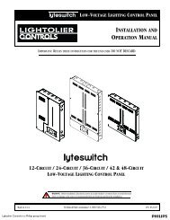
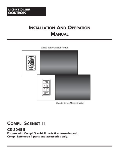
INSTALLATION AND OPERATIONMANUALEllipse Series Master StationClassic Series Master StationCOMPLI SCENIST IICS-2045IIFor use with Compli Scenist II parts & accessories <strong>and</strong>Compli Lytemode ll parts <strong>and</strong> accessories only.
INSTALLATION AND OPERATIONCOMPLI SCENIST IITABLE OF CONTENTSSPECIFICATIONCompli Scenist II, CS-2045II ......................................................................................... 1CONTROLSON Preset Pushbutton ....................................................................................................... 2A, B, C <strong>and</strong> D Presets .......................................................................................................... 2OFF Pushbutton .................................................................................................................. 2SET Pushbutton .................................................................................................................. 2All Raise/Lower Pushbuttons ............................................................................................. 2Fade Rate Display ............................................................................................................... 2Fade Rate RAISE/LOWER Pushbuttons .............................................................................. 2Channel Display .................................................................................................................. 2Channel RAISE/LOWER Pushbuttons ................................................................................ 2PROGRAM Pushbutton ...................................................................................................... 2RESET Pushbutton .............................................................................................................. 2BASIC OPERATIONChanging the <strong>Lighting</strong> Levels ........................................................................................... 3Learning a Preset ............................................................................................................... 3Recalling a Preset .............................................................................................................. 3Turning the Lights OFF ..................................................................................................... 4Skipping the Fade Rate ..................................................................................................... 4Locking the Front Panel .................................................................................................... 4Unlocking the Front Panel ................................................................................................ 4INSTALLATION PROCEDUREBasic Installation ................................................................................................................ 5Remote Inputs Installation ................................................................................................ 7Channel Exp<strong>and</strong>er Installation .......................................................................................... 10RS-485 Network Installation ............................................................................................. 2PROGRAMMINGGlobal Addressing ............................................................................................................. 11Enable Panel Lock ............................................................................................................. 12Remote Channel Mastering (Raise/Lower) ...................................................................... 12Automatic Cycling Mode .................................................................................................. 13Remote Terminal Strip Modes .......................................................................................... 14Alarm Flash/Full ................................................................................................................ 15Non Dim Assignment ........................................................................................................ 15Selective Learn Lock ("Designer Presets") ........................................................................ 16Channel Exclusion from Preset ........................................................................................ 17Channel Expansion ........................................................................................................... 18
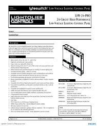
INSTALLATION AND OPERATIONCOMPLI SCENIST II 1DESCRIPTIONCOMPL SCENIST - CS-2045 IISPECIFICATION GRADE LIGHTING CONTROL 2000 Watt maximum capacity for:• Inc<strong>and</strong>escent• Fluorescent 1• Low Voltage Inc<strong>and</strong>escent 1• Neon/Cold Cathode• Non-dims for Fluorescent or General Inductive LoadsSPECIFICATIONThe Lightolier <strong>Controls</strong> Compli Scenist II is a solid-state device with integral dimmers intendedto control 4 separate lighting channels.The Compli Scenist II mounts in a st<strong>and</strong>ard wall box 2<strong>and</strong> uses st<strong>and</strong>ard wiring techniques.The Compli Scenist II has the following basic features:✓✓✓✓✓✓✓✓✓✓✓✓✓✓✓Four complete dimmers in one enclosure.Total power capacity of 2000 Watts.Any channel may control up to 800 Watts.One second to one hour fades between scenes with instant override.Any channel may be programmed to be a Non Dim.One Fluorescent Channel for use with fixtures utilizing dimming ballasts.Both preset <strong>and</strong> raise/lower remotes can be attached.Any preset may be locked (Designer Presets).Any channel may be excluded from any preset.Preset switch area may be located on the right or left.Two units may be programmed together to make 8 channels.Entire panel may be locked to avoid tampering.Alarm system input.Fully automatic cycle mode for animated displays.Fully compatible with Lytemode, Compli RS-485 Network.1Special restrictions apply to both Fluorescent <strong>and</strong> Low Voltage Loads. See appropriate Sections.1Deep wallbox is strongly recommended.
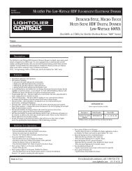
INSTALLATION AND OPERATION COMPLI SCENIST II 2CONTROLS168524311 2 3 423411105791. ON Preset PushbuttonPressing the ON pushbutton will fade the lights to their normal levels.2. A, B, C <strong>and</strong> D PresetsPressing any of the Preset pushbuttons will fade the lights to the presets that have been learned.3. OFF PushbuttonPressing the OFF pushbutton fades all the lights out.4. SET PushbuttonPressing the SET pushbutton will cause the indicators on the preset pushbuttons to cycle, askingwhich preset should be “learned?” Pressing ON or any Preset will “learn” the current lightinglevels <strong>and</strong> fade rate into that preset.5. All Raise/Lower PushbuttonsPressing the All Raise or All Lower pushbutton will cause the level of all the channels toincrease or decrease.This can be done at any time <strong>and</strong> will not affect the “learned” levels.6. Fade Rate DisplayThis indicator displays the current fade rate.7. Fade Rate RAISE/LOWER PushbuttonsThese pushbuttons increase or decrease the fade rate, or they are used to set the fade rate of apreset before it is “learned”.8. Channel DisplayThese bar graphs display the relative level of each channel.9. Channel RAISE/LOWER PushbuttonsPressing any channel Raise or Lower will cause the level of that channel to increase or decrease.This can be done at any time <strong>and</strong> will not affect the “learned” levels.10. PROGRAM PushbuttonThis pushbutton is located under the faceplate <strong>and</strong> is pressed with a stylus, such as a ballpoint pen. It is used to configure the Compli Scenist II for a particular application. See thePROGRAMMING chapter on page 12.11. RESET PushbuttonThe pushbutton is located under the faceplate <strong>and</strong> is pressed with a stylus, such as a ball pointpen. Should the Compli Scenist II malfunction for any reason, hold OFF <strong>and</strong> press Reset torestore unit to factory default, this will remove all special programming including scenes.
INSTALLATION AND OPERATION COMPLI SCENIST II 3BASIC OPERATIONChanging the <strong>Lighting</strong> LevelsDESCRIPTIONThe current level of the lights can be changed at any time by using the RAISE or LOWERpushbutton associated with each channel. ALL RAISE <strong>and</strong> ALL LOWER will increase ordecrease all channels.EXAMPLERaise Channel 1 to 50% <strong>and</strong> raise Channel 3 to 75%1. Press <strong>and</strong> hold the CHANNEL 1RAISE pushbutton.2. Notice that both the lights connected to Channel 1, <strong>and</strong> the Channel 1 bargraph increase.3. Release the pushbutton when 4 marks are illuminated on the bar graph.4. Press <strong>and</strong> hold the CHANNEL 3RAISE pushbutton.5. Release the pushbutton when 6 marks are illuminated on the bar graph.Learning a PresetDESCRIPTIONBefore a preset is “learned” (set in memory) the length of the fade must be set (fade rate).The FADE RATE RAISE <strong>and</strong> FADE RATE LOWER pushbuttons are used to set the length offade.After the desired fade rate has been selected, press the SET pushbutton.This willcause the indicator for the preset pushbuttons to cycle, asking where the preset should be“learned”. Pressing a preset pushbutton will “learn” the current levels <strong>and</strong> fade rate intothat preset.The cycling will stop <strong>and</strong> the “learned” preset will be illuminated.EXAMPLESave the current levels in the ON preset with a 3 second fade rate.1. Press the FADE RATE RAISE pushbutton 3 times to set the fade rate to 3 seconds.2. Press the SET pushbutton. Note: the preset indicators cycle.3. Press the ON pushbutton to learn the current levels in the ON preset.Recalling a PresetDESCRIPTIONPressing any of the PRESET pushbuttons (including ON) will cause the lights to fade tothe levels at the fade rate “learned”.The PRESET pushbutton will flash until the fade iscomplete. Pressing the same PRESET pushbutton again will cause the lights to go to the“learned” levels instantly.EXAMPLERecall the ON preset.1. Press the ON pushbutton.2. Notice the bar graph levels change <strong>and</strong> the ON pushbutton flashes.
INSTALLATION AND OPERATION COMPLI SCENIST II 4Turning the Lights OFFDESCRIPTIONPressing the OFF pushbutton will cause the lights to fade out.The OFF pushbuttonwill flash until the fade is complete. Pressing the OFF pushbutton again will cause thelights to go out instantly.EXAMPLETurn the lights offPress the OFF pushbutton.Skipping the Fade RateDESCRIPTIONThe user can skip the “fade rate” on any preset including ON <strong>and</strong> OFF by pressing thepreset pushbutton two times.This will make the change instantly.EXAMPLETurn the lights on instantly.Press the ON pushbutton twice.Locking the Front PanelDESCRIPTIONIf the Enable Panel Lock function is turned on (See Enable Panel Lock on page 12) all ofthe pushbuttons on the front panel may be locked to avoid tampering.To lock the frontpanel press <strong>and</strong> hold the FADE RATE DOWN pushbutton for two seconds.A double barwill appear across all the bar graphs to indicate the panel is locked.After the panel islocked the pushbuttons will have no effect until the “password code” is entered.Also, see Selective Learn Lock on page 18 for other ways to prevent tampering.EXAMPLE1. Select the PRESET desired.2. Press <strong>and</strong> Hold the FADE RATE DOWN pushbutton for two seconds.Unlocking the Front PanelDESCRIPTIONA panel that is locked, following the procedure above, can be unlocked by entering the“password code”.The “password code” is contained in the example below.EXAMPLEUnlock a locked panel1. Press the PRESET A pushbutton2. Press the ON pushbutton3. Press the PRESET B pushbutton4. The panel is unlocked
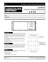
INSTALLATION AND OPERATION COMPLI SCENIST II 5INSTALLATION PROCEDUREWARNINGTo avoid fire, damage to the control, shock, or serious injury: turn off power at fuses or circuitbreakers <strong>and</strong> test the circuits to make sure that the power is off before wiring! Use only with copperor copper clad wire. It is recommended that a qualified electrician perform this <strong>installation</strong>.Load #1REDLoad #2REDLoad #3REDLoad #4WHITE orYELLOW120V AC LINENEUTRALHOTWHITEBLACK11 2 3 4234GREEN1. If applicable, remove faceplate <strong>and</strong> screws from existing switches, <strong>and</strong> remove existingswitches from wall box. Detach wires.2. Unpack Compli Scenist II <strong>and</strong> accessories from carton. Carefully remove faceplatefrom preset pushbuttons.3. Connect the Green wire to Earth Ground.4. Connect the White wire to Neutral.5. Connect the Black wire to Hot (Single 20 Amp Circuit.)Attaching Wire ConnectorRemove 1/2” insulation from wires. Hold bare ends of wires together <strong>and</strong> push firmlyinto connector. Screw wire connector on clockwise making sure that no bare wire shows belowwire connector.6. Connect the first three load circuits to the three red wires, <strong>and</strong> connect the fourth load circuitto the yellow (white with yellow b<strong>and</strong>) wire. No single load circuit should exceed 800 Watts<strong>and</strong> the total load should not exceed 200 Watts. Note: If using a dimmed fluorescent load seeFluorescent Installation Section on the following page before proceeding.7. If remotes, Channel Extender, or RS-485 Network (LAN) are to be used complete the appropriatesection before proceeding.8. Gently push wires <strong>and</strong> Compli Scenist II into wall box. Firmly fasten with the four longmounting screws.9. Before attaching stick-on labels (Classic Series only) or replacing face plate; restore powerat fuse or circuit breaker. Note: If you wish to program any special function (includingFluorescent or Non-Dim) see the programming section of the <strong>manual</strong> before proceeding.10. Check the Compli Scenist II for proper <strong>operation</strong>.11. It is suggested that presets should be “Learned” at this time (See Basic Operation).We suggestthat the ON preset be “Learned” as the Normal lighting in the room.Preset A might be “Learned” as Clean-up with all circuits at or near full.Preset B might be “Learned” as a low Security preset with just enough light to walk safelythrough the room.This will leave Presets C <strong>and</strong> D for the owners imagination.12. It will make the Compli Scenist II much easier to use if the labels supplied in the accessory kitare attached to identify each channel <strong>and</strong> preset. Please refer to detailed instructions packedwith accessory kit. (Classic Series Only)13. Please leave this <strong>manual</strong> <strong>and</strong> the sheets of labels for the owner.
INSTALLATION AND OPERATION COMPLI SCENIST II 6DIMMED FLUORESCENT INSTALLATIONLAMPSBALLASTLoad #1REDLoad #2REDLoad #3REDLoad #4SWITCHED HOTYELLOW(White with Yellow)120V AC LINENEUTRALHOTWHITEBLACK11 2 3 4234GREEN1. Connect the “switched hot” (heater) to the yellow (white with yellow b<strong>and</strong>) wire <strong>and</strong> the load(control) to circuit number three.2. Lightolier <strong>Controls</strong> strongly advises using fluorescent dimming ballasts which contain highpeaking circuits. these ballasts extend the low end dimming range considerably <strong>and</strong> have lesstendency to flicker.3. Allow five minutes for fluorescent lamps to warm up before making final settings. For bestperformance, lamps should be aged at full brightness for 100 hours.4. Refer to following chart for Ballast selection.Dimmable Ballast Type Number of Lamps Ballast Current Maximum numberper Ballast in Amps of Lamps (800W)GE 8G5001 3,4 1 .43 14GE 8G5007 3,4 2 .86 14UNIVERSAL 550L-TC-P 4 1 .43 14UNIVERSAL 550L 1 .43 14UNIVERSAL 5502A-TC-P 3,5 2 .43 14UNIVERSAL 5502A 2 .43 14ADVANCE DIM140-H-TP 3,5 1 .43 14ADVANCE DIM140-H 1 .43 14ADVANCE DIM240-H-TP 3,5 2 .43 14ADVANCE DIM240-H 2 .43 14MINIMUM NUMBER OF LAMPS 25. Continue with item 7 of Basic Installation on previous page. After unit is installed <strong>and</strong> poweris restored the unit must be programmed. See Dimmable Fluorescent on page 10.Remote Inputs InstallationThe sixteen position terminal strip can be used to connect your Compli Scenist II to variousCompli II accessories.The section below describes the different configurations of this terminalstrip. Use 300 volt, #18 through #22 AWG wire only.NOTEYou must set up the mode of <strong>operation</strong> for the terminal strip.Follow the instructions in the Remote terminal Strip Modes Section on page 12.3“P” Related Ballast4While these Ballast are compatible with 30 <strong>and</strong> 40 watt lamps. do not intermix types on the same unit.De-rate total wattage 10% when using 30 watt lamps.5“P” Related Ballast are recommended. However fixtures must be capable of dissipating heat output of a ‘P” Ballastswithout tripping terminal breaker.
INSTALLATION AND OPERATION COMPLI SCENIST II 7Terminal Strip SignalsThe signals on the 16 pin terminal strip are as follows in each mode:PIN NUMBER MODE 0 MODE 1 MODE 2 MODE 312345678910111213141516LED CommonOFF LEDD LEDC LEDB LEDA LEDON LEDButton CommonLower(1)Raise(1)OFF ButtonD ButtonC ButtonB ButtonA ButtonOn ButtonLED CommonOFF LEDI LEDH LEDG LEDF LEDE LEDButton CommonLower(1)Raise(1)OFF ButtonI ButtonH ButtonG ButtonF ButtonE ButtonLED CommonOFF LEDON LEDButton CommonLower(3)Raise(3)OFF ButtonLower(2)Raise(2)Lower(1)Raise(1)ON ButtonLED CommonOFF LEDD LEDC LEDB LEDA LEDON LEDButton CommonAlarmCycleOFF ButtonD ButtonC ButtonB ButtonA ButtonON ButtonCS-2045II with Preset Remote (CSR-5)CS-2045II MODE O CSR-533 4 41234567891011121314151689101112131476543211 LED Common 72 OFF LED 63 D LED 54 C LED 45 B LED 36 A LED 27 ON LED 18 Button Grnd 89 Lower10 Raise11 OFF Button 912 D Button 1013 C Button 1114 B Button 1215 A Button 1316 On Button 14CS-2045II with Raise/Lower Remote (CSR-2)CS-2045II MODE O CSR-28 Button Grnd 89 Lower 910 Raise 1433 4 4123456789101112131415161413121110RAISELOWER98
INSTALLATION AND OPERATION COMPLI SCENIST II 8Compli Scenist II with (CSR-2) <strong>and</strong> Alarm InputCS-2045II Mode 1 CSR-2 ALARM33 4 412345678910111213141516ON8OFF9101112131476543211 LED Common 72 OFF LED 67 ON LED 18 Button GND 8 X9 ALARM X11 OFF Button 916 ON Button 14ALARMSYSTEMCompli Scenist II with CSR-5 used as Preset Exp<strong>and</strong>erCS-2045II MODE O CSR-533 4 41234567891011121314151689101112131476543211 LED Common 12 OFF LED 23 I LED 34 H LED 45 G LED 56 F LED 67 E LED 78 Button GND 811 OFF Button 912 I Button 1013 H Button 1114 G Button 1215 F Button 1316 E Button 14Compli Scenist II with Three (CSR-2) used as Raise/Lower Remotes33 4 412345678910111213141516RAISELOWER7654321RAISELOWER7654321RAISELOWER7654321CS-2045II Mode 2 R/L #1 R/L #2 R/L #38 BUTTON GND 8 8 815 RAISE (1) 1414 LOWER (1) 913 RAISE (2) 1412 LOWER (2) 910 RAISE (3) 149 LOWER (3) 9
CONTEMPORARY DISTRIBUTION AND LATE-QUATERNARY STRATIGRAPHY OF DIATOMS IN THE JUNIN PLAIN29Non-significant environmental parameters wereexcluded from further analyses. With the selectedset of significant parameters, we ran a series of constrainedCCAs on each individual environmentalvariable. The significance of the first axis was testedusing Monte Carlo permutation tests (p ≤ 0.05) with199 unrestricted permutations. Any non-significantenvironmental variable was excluded from furtheranalyses. An additional CCA was performed withthe statistically significant environmental parameters,<strong>and</strong> then we identified highly correlated environmentalvariable pairs (-0.6> r >0.6) from the Pearsoncorrelation matrix. Partial CCAs were performed foreach correlated pair; one variable as the sole variable<strong>and</strong> the other as covariable, <strong>and</strong> the significance ofeach pair of variables was determined with a MonteCarlo permutation test on the 1 st axis (P ≤ 0.05, 999unrestricted permutations). Non-significant resultsindicate that the variate-covariate variables explainedthe same part of data variance; in this case we choosethe variable explaining the highest amount of variancein the original CCA1.ResultsWater characterization of high-altitude lentic <strong>and</strong>lotic environmentsWater bodies in the Junin Plain <strong>and</strong> surroundingareas contain calcium-rich alkaline waters. Cationcomposition indicates elevated concentration of Ca +2(range from 6.9 to 99.2 mg/L, n=31) with respect toMg +2 <strong>and</strong> Na +1 +K +1 (Fig. 4a), <strong>and</strong> alkalinity is high(40.0-240.5 mgCaCO 3/L, n=32) with respect to SO4 -2<strong>and</strong> Cl -1 concentration (Fig. 4b). Waters have circumneutralto alkaline pH (6.8-9.3, n=33); moderate tohigh conductivity (168-1184 μS/cm, n=32), <strong>and</strong> lowto moderate dissolved oxygen (2.6-7.5 mg/L, n=29).Total phosphorous concentrations range from 5.9 to60.7 μg/L (n=21), total nitrogen from 118.2 to 1774.5μg/L (n=21) (Table 2), <strong>and</strong> silica concentrations rangebetween 0.3 <strong>and</strong> 6.6 mg/L (n=31).Modern diatom communitiesThe diatom composition in macrophyte samplesis represented by 58 species (relative abundance>3%) distributed over the 4 environments (Fig. 5).The most common species in lakeshore regions areGomphonema minutum, Nitzschia denticula, Synedraulna, Denticula elegans, Diatoma vulgaris,<strong>and</strong> Cymbella cistula. Some planktonic species arealso encountered in this association, such as Synedraacus var. angustissima, Synedra delicatissima, <strong>and</strong>Fragilaria crotonensis. Dominant taxa in streammacrophyte samples are Achnanthidium minutissimum,Synedra ulna, Cocconeis placentula, Naviculacryptocephala, <strong>and</strong> Staurosira spp. Wetl<strong>and</strong> macrophytesamples are dominated by Synedra delicatissima,N. cryptocephala, <strong>and</strong> Navicula radiosa. Speciescomposition in spring samples is more diverse<strong>and</strong> includes A. minutissimum, Diatoma mesodon, N.denticula, G. parvulum, Naviculadicta seminulum,Planothidium lanceolata, <strong>and</strong> Staurosira spp.Common lakeshore <strong>and</strong> lake offshore planktonicspecies from plankton tows (Fig. 6) are Synedra delicatissima,Gomphonema minutum, Fragilaria crotonensis,A. minutissimum, <strong>and</strong> Fragilaria vaucheriae.Stream planktonic diatom samples were dominatedby A. minutissimum, with low percentages of S.delicatissima, S. ulna, F. capucina, N. palea, <strong>and</strong> P.zeilleri. Surface-sediment samples from lakes havea diatom flora primarily composed of Staurosira cf.S. construens var. venter, Staurosira construens var.construens, <strong>and</strong> A. minutissimum, whereas streamsediment samples contained Staurosira cf. S. construensvar. venter, A. minutissimum, Staurosiraconstruens var. subsalina, Staurosira spp., Amphorapediculus, <strong>and</strong> Navicula capitatoradiata (Fig. 6).Samples from rock-scrub <strong>and</strong> algal biohermenvironments have a lower diatom diversity of 15species (Fig. 7). Dominant species for stream <strong>and</strong>spring habitats are A. minutissimum, C. placentula,<strong>and</strong> Reimera sinuata, whereas algal bioherm taxaare A. minutissimum, D. elegans, <strong>and</strong> Encyonopsismicrocephala.The fossil recordLake Junin sediments (core JU96-A) are composedof four distinct lithological units (Fig. 8): 1)18.79 to 14.5-m: gray to tan silt with disseminatedplant remains <strong>and</strong> mollusk shells; 2) 14.5 to 11.2m:inorganic massive gray silt; 3) 11.2 to 9.7m: darkorganic-rich silt <strong>and</strong> gyttja; <strong>and</strong> 4) 9.7 to 0.37m:yellowish-brown laminated marl with abundantgastropod shells.Diatom species composition of this 19-m coresuggests three distinct zones. Diatoms from thelower lithologic unit (18.79 to 14.5 m, Fig. 8) consistof benthic taxa, with the dominance of Staurosirasp. cf. S. construens var. venter (up to 85%) <strong>and</strong>other benthic littoral <strong>and</strong> tycoplanktonic species,such as Pseudostaurosira brevistrata, Staurosiraconstruens var. construens, Staurosira construensvar. subsalina, <strong>and</strong> Staurosirella pinnata. In somelevels the epiphytic diatoms Cocconeis placentula
INSTALLATION AND OPERATION COMPLI SCENIST II 10PROGRAMMINGThe Compli Scenist II has the ability to program many special functions that allow it toperform <strong>operation</strong>s normally reserved for large central computer systems.All of theseprogramming modes are accessed by holding down the PROGRAM pushbutton <strong>and</strong> pressing oneadditional pushbuttons on the panel.This is made clear under the “To Access” heading of eachsection.The PROGRAM pushbutton is under the faceplate <strong>and</strong> requires a stylus, such as a ball pointpen, to push.Enable Panel LockTo AccessHold down the PROGRAMPress FADE RATE DOWNIndication on Rate DisplayDESCRIPTIONAllows the user to “lock the entire” control panel, <strong>and</strong>/or remote stations including thepreset pushbuttons. Used to prevent unwanted tampering with the control panel.If enabled the panel maybe be locked by holding FADE RATE DOWN for two seconds,during normal <strong>operation</strong>.If a button is pushed while the panel is locked a special warning display will appearon the Bar Graphs.To unlock enter “password code” (PRESET A, ON, PRESET B)ProgramPress ON (Top Large Button) to enable/disable panel lock.ON will illuminate if enabled.ExitSET will return to normal <strong>operation</strong>.EXAMPLEEnable panel lock1. Hold PROGRAM <strong>and</strong> press FADE RATE DOWN2. Press ON (to illuminate button)3. Press SETIndication on Rate Display
INSTALLATION AND OPERATION COMPLI SCENIST II 11Dimmable FluorescentTo AccessHold down the PROGRAMPress FADE RATE DOWNIndication on Fade Rate DisplayDESCRIPTIONWhen set, channel 3 <strong>and</strong> 4 of the Compli Scenist II are for use on a fluorescentluminaire with a magnetic dimming ballast.Channel 3 is attached to the dimming load <strong>and</strong> channel 4 is attached to the“Switched Hot” (heater).Whenever channel 3 is above a level of zero channel 4 will be full on.ProgramPress PRESET A (second row, left) to enable/disable.The PRESET A will illuminate if enabled.ExitSET will return to normal <strong>operation</strong>.EXAMPLEEnable Compli Scenist II Fluorescent1. Hold PROGRAM <strong>and</strong> press FADE RATE DOWN2. Press PRESET A3. Press SET
INSTALLATION AND OPERATION COMPLI SCENIST II 12PROGRAMMING (Continued)Automatic Cycling ModeTo AccessHold down the PROGRAMPress FADE RATE DOWNIndication on Fade Rate DisplayDESCRIPTIONThis feature allows a Compli Scenist II to automatically sequence from scene to scene.If set, the first five presets (ON,A,B,C,D) will cycle automatically.When PRESET B is finished PRESET C will start <strong>and</strong> so on.When the fade is complete it will move to the next scene at the scenes “fade rate”.This can be used for store windows, sculpture lighting or even fountain control.ProgramPress PRESET B (second row, right) to enable/disable.The PRESET B will illuminate if enabled.ExitSET will return to normal <strong>operation</strong>.EXAMPLEEnable Fully Automatic1. Hold PROGRAM <strong>and</strong> press FADE RATE DOWN2. Press PRESET B3. Press SET
INSTALLATION AND OPERATION COMPLI SCENIST II 13Remote Terminal Strip ModesDESCRIPTIONEvery unit has a 16 position terminal strip.This strip is divided into 8 inputs with common<strong>and</strong> 6 LED outputs with drive. The function of these inputs <strong>and</strong> outputs can bechanged by the settings of PRESET A <strong>and</strong> PRESET B.To AccessHold down the PROGRAM <strong>and</strong> press FADE RATE DOWNPress FADE RATE UPIndication on Rate DisplayProgramSet PRESET A <strong>and</strong> PRESET B as illustrated in the following chart:MODE Preset Button Input Output Input OnlyA B 1 2 3 4 5 6 7 80 OFF OFF ON A B C D OFF Raise(1) Lower(1)1 OFF ON E F G H I OFF Raise(1) Lower(1)2 ON OFF ON Raise(1) Lower(1) Raise(2) Lower(2) OFF Raise(2) Lower(2)3 ON ON ON A B C D OFF Cinema AlarmCycleCinema CycleA remote closure causes the unit to cycle through PRESET A, B, C <strong>and</strong> D.This closurecomes from the projector <strong>and</strong> can automatically control the lights in the movie theater.The ON preset is reserved for a ‘clean up/emergency’ preset.AlarmA remote closure comes from the alarm system <strong>and</strong> causes all the channels to either goto Full on, or cycle between Full off <strong>and</strong> off.See the Alarm Flash/Full section below.ExitSET will return to normal <strong>operation</strong>.EXAMPLESet Local remotes for E - OFF <strong>and</strong> Raise/Lower1. Hold PROGRAM <strong>and</strong> press FADE RATE DOWN2. Press FADE RATE UP3. Press PRESET A4. Press SET
INSTALLATION AND OPERATION COMPLI SCENIST II 15ProgramEach CHANNEL UP will change that channel to a non dim.All LEDs in that channel’s bar graph will be on.The CHANNEL DOWN pushbutton will change that channel back to a dimmer.That channel’s bar graph will be off.ExitSET will return to normal <strong>operation</strong>.EXAMPLESet channels 2 <strong>and</strong> 4 to be non dims1. Hold PROGRAM <strong>and</strong> press ALL UP2. Press CHANNEL 2 UP3. Press CHANNEL 4 UP4. Press SETRemote Channel Mastering (Raise/Lower)To AccessHold down the PROGRAMPress ALL DOWNIndication on Rate DisplayThe bottom LED will flash to indicate Raise/Lower Master number one can be set up.Note:Only one of four Remote Terminal Strip Modes supports more than oneRaise/Lower Master. See Remote Terminal Strip Modes on page 13.DESCRIPTIONAny or all channels can be set to respond to Raise/Lower inputs from channel masters.ProgramCHANNEL UP will assign that channel to the Raise/Lower inputs from the terminal strip.CHANNEL DOWN will cancel the assignment.FADE RATE UP will select next Local Raise/Lower Master.DisplayAssigned channel will display:ExitSET will return to normal <strong>operation</strong>.EXAMPLEAssign channels 2 <strong>and</strong> 4 to local Raise/Lower number one <strong>and</strong> assign channel 6 to localRaise/Lower number three.1. Hold PROGRAM <strong>and</strong> press ALL DOWN2. Press CHANNEL 2 UP3. Press CHANNEL 4 UP4. Press FADE RATE UP twice5. Press CHANNEL 6 UP6. Press SET
INSTALLATION AND OPERATION COMPLI SCENIST II 16Selective Learn Lock (“Designer Presets”)DESCRIPTIONLearn lock is intended to allow “designer presets.” Certain presets can be set by thedesigner or the owner <strong>and</strong> then locked so they can not be accidentally changed duringnormal use.To AccessHold down PROGRAMPress SETIndication on Rate DisplayProgramPress any PRESET to lock that preset.LOCKED presets will flash.Press again to cancel.ExitSET will return to normal <strong>operation</strong>EXAMPLELock presets B <strong>and</strong> C1. Hold Program <strong>and</strong> press SET2. Press PRESET B3. Press PRESET C4. Press SETChannel ExpansionDESCRIPTIONAny two Compli Scenist II’s can be paired together to double the numberof channels.All pushbuttons will mimic on both panels except CHANNEL UP ANDCHANNEL DOWN. Programming must be done on both Compli Scenist II’s.This section assumes that no other RS-485 network functions are being used.If other RS-485 network functions are being used refer to the Compli Lytemode II Manualfor further information on setting up channels <strong>and</strong> exp<strong>and</strong>ers.ProgramOn Compli Scenist One:Set the ID code to one.Set theexp<strong>and</strong>er code to two.On Compli Scenist Two:Set the ID code to two.Set theexp<strong>and</strong>er code to one.CHANNEL UP increases the ID code.CHANNEL DOWN decreases the ID code.FADE RATE UP selects the Exp<strong>and</strong>er code.FADE RATE DOWN selects the ID code.
INSTALLATION AND OPERATION COMPLI SCENIST II 17The ID will be displayed on all bar graphs in binary.ExitSET will return to normal <strong>operation</strong>.EXAMPLESet up two Compli Scenist II’s for Channel Expansion1. On one Compli Scenist II2. HOLD PROGRAM <strong>and</strong> press OFF.3. Press CHANNEL 1 UP one time.4. Press FADE RATE UP.5. Press CHANNEL 1 UP two times.6. Press SET.7. On the other Compli Scenist II8. HOLD PROGRAM <strong>and</strong> press OFF.9. Press CHANNEL 1 UP two times.10. Press FADE RATE UP.11. Press CHANNEL 1 UP one time.12. Press SET.Channel Exclusion from PresetDESCRIPTIONAny channel can be excluded from any PRESET.If a channel is excluded from a PRESET it’s level will not change when that PRESET ispressed.This will allow a single unit to control two rooms with some PRESETS in oneroom, some in the other <strong>and</strong> some in both.To AccessHold down PROGRAMPress any PRESET but OFFIndication on Rate DisplayProgramPress any Preset to select preset.Press CHANNEL UP to exclude that channel.ExitSet will return to normal <strong>operation</strong>.EXAMPLEExclude channels 1 <strong>and</strong> 2 from PRESET B1. Hold PROGRAM <strong>and</strong> press PRESET B2. Press PRESET B again.3. Press CHANNEL 1 UP4. Press CHANNEL 2 UP5. Press SET
P/N 85-6271