Variable-Area Flowmeter Device Description - Adinco bv
Variable-Area Flowmeter Device Description - Adinco bv
Variable-Area Flowmeter Device Description - Adinco bv

Create successful ePaper yourself
Turn your PDF publications into a flip-book with our unique Google optimized e-Paper software.
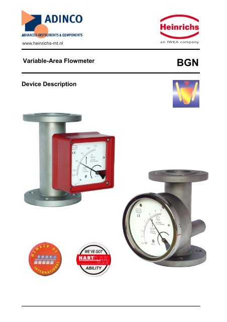
www.heinrichs-mt.nl<br />
<strong>Variable</strong>-<strong>Area</strong> <strong>Flowmeter</strong><br />
BGN<br />
<strong>Device</strong> <strong>Description</strong>
Heinrichs Messtechnik<br />
<strong>Device</strong> <strong>Description</strong> <strong>Variable</strong> <strong>Area</strong> <strong>Flowmeter</strong> BGN<br />
Contents<br />
1 IDENTIFICATION ............................................................................................................................................................. 4<br />
1.1 Supplier/manufacturer .............................................................................................................................4<br />
1.2 Product type ..............................................................................................................................................4<br />
1.3 Product name ............................................................................................................................................4<br />
1.4 Issue date ...................................................................................................................................................4<br />
1.5 Version no..................................................................................................................................................4<br />
2 APPLICATIONS ............................................................................................................................................................... 4<br />
3 OPERATIONAL MODE AND SYSTEM DESIGN.............................................................................................................. 4<br />
3.1 Measuring principle..................................................................................................................................4<br />
3.2 System design ............................................................................................................................................4<br />
4 INPUT ........................................................................................................................................................................ 4<br />
4.1 Measured variable ....................................................................................................................................4<br />
4.2 Measuring range (lower-range and upper-range value)........................................................................4<br />
4.3 Measuring range table..............................................................................................................................5<br />
5 OUTPUT ........................................................................................................................................................................ 6<br />
5.1 Binary output ............................................................................................................................................6<br />
5.1.1 KEI 1 or KEI 2 limit transducers..........................................................................................................6<br />
5.1.2 KEM 1 or KEM 2 limit transducers (special version) ..........................................................................6<br />
5.2 Analog output with the ES magneto-electric transmitter......................................................................6<br />
5.3 Analog output with the KINAX 3W2 angle-of-rotation transmitter ....................................................6<br />
6 CHARACTERISTIC VALUES........................................................................................................................................... 6<br />
6.1 Measuring accuracy..................................................................................................................................6<br />
6.1.1 Reference conditions ............................................................................................................................6<br />
6.1.2 Measured error......................................................................................................................................6<br />
6.1.3 Repeatability.........................................................................................................................................6<br />
6.2 Influence of ambient temperature ...........................................................................................................6<br />
6.3 Influence of fluid temperature .................................................................................................................6<br />
7 CONDITIONS OF USE ..................................................................................................................................................... 6<br />
7.1 Mounting requirements............................................................................................................................6<br />
7.1.1 Mounting/start-up .................................................................................................................................7<br />
7.1.2 <strong>Device</strong> settings......................................................................................................................................7<br />
7.1.3 Adjusting the limit transducer ..............................................................................................................7<br />
7.1.4 Operation in hazardous areas................................................................................................................8<br />
7.2 Ambient conditions ...................................................................................................................................8<br />
7.2.1 Ambient temperature ranges.................................................................................................................8<br />
7.2.2 Storage temperature..............................................................................................................................8<br />
7.2.3 Climatic category..................................................................................................................................8<br />
7.2.4 Degree of protection .............................................................................................................................8<br />
7.2.5 Shock resistance/vibration resistance ...................................................................................................8<br />
7.2.6 Electromagnetic compatibility..............................................................................................................8<br />
7.3 Fluid conditions.........................................................................................................................................9<br />
7.3.1 Fluid temperature ranges ......................................................................................................................9<br />
7.3.2 Diagrams: Max. ambient temperature based on the fluid temperature for the ES ................................9<br />
7.3.3 Fluid pressure limit.............................................................................................................................10<br />
7.3.4 Inlet and outlet sections ......................................................................................................................10<br />
7.3.5 Physical state ......................................................................................................................................10<br />
7.3.6 Density................................................................................................................................................10<br />
7.3.7 Viscosity.............................................................................................................................................10<br />
Page 2 of 28
Heinrichs Messtechnik<br />
<strong>Device</strong> <strong>Description</strong> <strong>Variable</strong> <strong>Area</strong> <strong>Flowmeter</strong> BGN<br />
7.3.8 Pressure (for gas measurement)..........................................................................................................10<br />
7.3.9 Pressure loss .......................................................................................................................................10<br />
8 CONSTRUCTION DETAILS........................................................................................................................................... 11<br />
8.1 Type of construction/dimensions ...........................................................................................................11<br />
8.1.1 Aluminum indicator housing ..............................................................................................................11<br />
8.1.2 Dimension drawing for heating connection........................................................................................11<br />
8.1.3 Indicator housing made of stainless steel............................................................................................12<br />
8.2 Weight......................................................................................................................................................12<br />
8.3 Material....................................................................................................................................................13<br />
8.4 Process connection ..................................................................................................................................13<br />
8.5 Magnetic filter .........................................................................................................................................13<br />
8.6 Electrical connection...............................................................................................................................14<br />
8.6.1 Wiring diagram for ES transmitter (signal output 4-20 mA with HART®).......................................14<br />
8.6.2 Wiring diagram for ES transmitter with 4-20 mA output and 2 limit transducers..............................14<br />
8.6.3 Wiring diagram for ES transmitter with 4- 20 mA output, pulse output and limit transducer............15<br />
8.6.4 Wiring diagram for inductive limit transducers..................................................................................15<br />
8.6.5 Wiring diagram for KINAX 3W2 transmitter with 4-20 mA output, 2 wires.....................................16<br />
8.6.6 Wiring diagram for KINAX 3W2 transmitter with 4-20 mA output, 3 wires.....................................16<br />
8.6.7 Wiring diagram for KINAX 3W2 transmitter with 4-20 mA output, 4 wires.....................................17<br />
8.6.8 Wiring diagram for KEM 1 and KEM 2 double-throw microswitches...............................................17<br />
9 INDICATOR UNIT........................................................................................................................................................... 18<br />
10 AUXILIARY POWER...................................................................................................................................................... 18<br />
11 CE MARK ...................................................................................................................................................................... 18<br />
12 ORDER INFORMATION................................................................................................................................................. 18<br />
12.1 Available accessories...............................................................................................................................18<br />
13 STANDARDS AND DIRECTIVES, CERTIFICATES AND APPROVALS........................................................................ 18<br />
14 REPLACEMENT PARTS................................................................................................................................................ 18<br />
15 EXPLODED VIEWS........................................................................................................................................................ 19<br />
15.1 Fitting with measuring element .............................................................................................................19<br />
15.1.1 BGN-.... Standard version..................................................................................................................19<br />
15.1.2 BGN-.... with spring stop...................................................................................................................19<br />
15.1.3 BGN-.... with damping piston.............................................................................................................19<br />
15.1.4 BGN-.... with damping piston and spring stop ...................................................................................20<br />
15.1.5 BGN-.... small measuring ranges........................................................................................................20<br />
15.2 Indicator unit...........................................................................................................................................21<br />
15.2.1 Complete indicator unit, local with scale............................................................................................21<br />
15.2.2 Complete indicator unit with 1 SJ 3,5 N limit transducer...................................................................21<br />
15.2.3 Complete indicator unit with 2 SJ 3,5 N limit transducers .................................................................21<br />
15.2.4 Complete indicator unit with E2 KINAX Ex transmitter....................................................................22<br />
15.2.5 Complete indicator unit with E2 KINAX Ex transmitter and 1 SJ 3,5 N limit transducer .................22<br />
15.2.6 Indicator unit with transmitter type ES Ex HART® ..........................................................................22<br />
16 EC TYPE EXAMINATION CERTIFICATE ...................................................................................................................... 23<br />
17 SALES REPRESENTATIVES ........................................................................................................................................ 28<br />
18 NOTES ...................................................................................................................................................................... 28<br />
Page 3 of 28
Heinrichs Messtechnik<br />
<strong>Device</strong> <strong>Description</strong> <strong>Variable</strong> <strong>Area</strong> <strong>Flowmeter</strong> BGN<br />
1 Identification<br />
1.1 Supplier/manufacturer<br />
Heinrichs Messtechnik GmbH<br />
Robert-Perthel-Str. 9 ⋅ D-50739 Köln<br />
Phone +49 (221) 49708 - 0<br />
Fax +49 (221) 49708 - 92<br />
Internet: http://www.heinrichs-mt.nl<br />
E-mail: mailto:info@heinrichs-mt.nl<br />
1.2 Product type<br />
<strong>Flowmeter</strong> in all-metal design based on the float principle<br />
1.3 Product name<br />
BGN with subgroups<br />
BGN-S (stainless steel)<br />
BGN-P (PTFE)<br />
BGN-H (Hastelloy)<br />
1.4 Issue date<br />
09/07/2003<br />
1.5 Version no.<br />
2.0<br />
File: BGN_GB_02_eng<br />
2 Applications<br />
The BGN meter is suitable for flow measurement of liquid or<br />
gaseous products in pipes. It shows the current flow rate in<br />
volume or mass per unit in time.<br />
Applications: flow measurement, dosing, monitoring,<br />
adjusting and control of liquid and gaseous products.<br />
The meter’s design makes it ideal for processes under<br />
difficult and adverse operating conditions.<br />
The devices are available with additional electrical<br />
equipment for process monitoring and control.<br />
3 Operational mode and system<br />
design<br />
3.1 Measuring principle<br />
The measuring element consists of a sharp-edged<br />
measuring ring (1) and a conical float (2). A medium flows<br />
from the bottom to the top through the measuring ring, lifting<br />
the float until the buoyancy force (A) and the weight of the<br />
float (Gs) establish equilibrium. As the height of the float<br />
varies, an annular clearance (S) proportional to the flow<br />
appears between the float and the measuring ring. The<br />
height of the float in the measuring ring is a measure of the<br />
flow. The permanent magnet (3) embedded in the float then<br />
transmits this measure to the scale and the optional<br />
electronic evaluators through a magnet tracking indicator<br />
system (4).<br />
3.2 System design<br />
The meter consists of a cylindrical fitting pipe with flange<br />
connections on both sides. For the measuring range from<br />
5 to 50 l/h, a measuring ring is inserted in the tube in which a<br />
conical float can move with vertical freedom. For small<br />
measuring ranges of up to 4–40 l/h, the measuring cell<br />
consists of a conical measuring tube with cylindrical float.<br />
The height of the float resulting from the flow rate is<br />
transmitted in a rotary motion by a built-in permanent<br />
magnet through a magnet tracking indicator system in a<br />
rotation to the pointer axis of the analog indicator unit.<br />
4 Input<br />
4.1 Measured variable<br />
Volume flow<br />
4.2 Measuring range (lower-range and<br />
upper-range value)<br />
The lower-range value is considered 10% of the upper-range<br />
value. Measuring range span: 10-100%<br />
Smallest measuring range: 0.5-5.0 l/h water<br />
Largest measuring range: 8.000-80.000 l/h water (stainless<br />
steel)<br />
Page 4 of 28
Heinrichs Messtechnik<br />
<strong>Device</strong> <strong>Description</strong> <strong>Variable</strong> <strong>Area</strong> <strong>Flowmeter</strong> BGN<br />
4.3 Measuring range table<br />
Nominal<br />
size (DN)<br />
Measuring<br />
range<br />
Measuring range for<br />
water at 1000 kg/m3<br />
Measuring range for air<br />
at 1.013 bars absolute<br />
pressure<br />
Pressure loss<br />
(mbar)<br />
Remarks<br />
15 A 0.5– 5.0 I/h 0.015 – 0.15 m 3 /h 40 1)+2)<br />
B 1.0 – 10 I/h 0.03 – 0.30 m 3 /h 44 1)+2)<br />
C 1.6 – 16 I/h 0.045 – 0.48 m 3 /h 40 1)+2)<br />
D 2.5 – 25 I/h 0.075 – 0.75 m 3 /h 40 +2)<br />
E 4.0 – 40 I/h 0.13 – 1.3 m 3 /h 40 +2)<br />
F 5.0 – 50 I/h 0.15 – 1.5 m 3 /h 40<br />
G 7.0 – 70 I/h 0.2 – 2.1 m 3 /h 40<br />
H 10 – 100 I/h 0.3 – 3.0 m 3 /h 60<br />
I 16 – 160 I/h 0.5 – 4.6 m 3 /h 60<br />
J 25 – 250 I/h 0.7 – 7.0 m 3 /h 60<br />
K 40 – 400 I/h 1.0 – 11 m 3 /h 70<br />
L 60 – 600 I/h 1.7 – 17 m 3 /h 80<br />
M 100 – 1000 I/h 3 – 30 m 3 /h 60 5)<br />
N 160 - 1600 I/h 4 – 46 m 3 /h 70 5)<br />
P 250 – 2500 I/h 7 – 70 m 3 /h 100 5)<br />
25 A 0.5 – 5.0 I/h 0.015 – 0.15 m 3 /h 40 1)+2)<br />
B 1.0 –10 I/h 0.03 – 0.30 m 3 /h 40 1)+2)<br />
C 1.6 –16 I/h 0.045 – 0.48 m 3 /h 40 1)+2)<br />
D 2.5 – 25 I/h 0.075 – 0.75 m 3 /h 40 +2)<br />
E 4.0 – 40 I/h 0.13 – 1.3 m 3 /h 40 +2)<br />
F 5.0 – 50 I/h 0.15 – 1.5 m 3 /h 40<br />
G 7.0 – 70 I/h 0.2 – 2.1 m 3 /h 40<br />
H 10 – 100 I/h 0.3 – 3.0 m 3 /h 60<br />
I 16 – 160 I/h 0.5 – 4.6 m 3 /h 60<br />
J 25 – 250 I/h 0.7 – 7.0 m 3 /h 60<br />
K 40 – 400 I/h 1.0 – 11 m 3 /h 70<br />
L 60 – 600 I/h 1.7 – 17 m 3 /h 80<br />
M 100 – 1000 I/h 3 – 30 m 3 /h 60<br />
N 160 – 1600 I/h 4 – 46 m 3 /h 70<br />
P 250 – 2500 I/h 7 – 70 m 3 /h 100<br />
Q 400 – 4000 I/h 11 – 110 m 3 /h 240 3)+ 4)<br />
40 P 250 – 2500 I/h 7 – 70 m 3 /h 50 3)<br />
Q 400 – 4000 I/h 11 – 110 m 3 /h 120 3)<br />
R 600 – 6000 I/h 17 – 170 m 3 /h 180 3)<br />
50 Q 400 – 4000 I/h 11 – 110 m 3 /h 80<br />
R 600 – 6000 I/h 17 – 170 m 3 /h 90<br />
S 1000 – 10000 I/h 29 – 290 m 3 /h 110<br />
T 1600 –16000 I/h 46 – 460 m 3 /h 230<br />
U 2500 – 25000 I/h 70 – 700 m 3 /h 500 3)+ 4)<br />
80 T 1600 – 16000 I/h 46 – 460 m 3 /h 70<br />
U 2500 – 25000 I/h 70 – 700 m 3 /h 100<br />
V 4000 – 40000 I/h 110 – 1100 m 3 /h 350<br />
100 V 4000 – 40000 I/h 110 – 1100 m 3 /h 120<br />
W 6000 – 60000 I/h 170 – 1700 m 3 /h 360<br />
X 8000 – 80000 I/h 240 - 2400 m 3 /h 600 3)+ 4)<br />
1) for P version (PTFE), float with tantalic collar, cone of borosilicate glass<br />
measuring range: A 0.7–7.0 l/h, B 1.2–12 l/h, C 2.0–20 l/h<br />
2) gas throttle in S version for gas measurement included in price (pressure loss 200 mbar)<br />
3) not available in P version<br />
4) conversion not possible<br />
5) only in S and H version, only with smaller sealing strip<br />
Page 5 of 28
Heinrichs Messtechnik<br />
<strong>Device</strong> <strong>Description</strong> <strong>Variable</strong> <strong>Area</strong> <strong>Flowmeter</strong> BGN<br />
5 Output<br />
Various electrical contact makers or transmitters may be<br />
installed in the indicator unit.<br />
5.1 Binary output<br />
Using the segments of the slot-type initiators or the eccentric<br />
discs of the microswitches, any switching point between 10%<br />
and 90% of the flow rate can be set.<br />
5.1.1 KEI 1 or KEI 2 limit transducers<br />
1 or 2 limit transducers,<br />
type SJ 3,5N, make Pepperl+Fuchs<br />
(special switch possible, e.g. SN version)<br />
Safety class: PTB Nr. 99 ATEX 2219 X<br />
PTB Nr. 00 ATEX 2048 X<br />
5.1.2 KEM 1 or KEM 2 limit transducers<br />
(special version)<br />
Double-throw microswitches whose switching point is<br />
activated by a cam plate.<br />
KEM 1 = 1 Double-throw microswitch<br />
KEM 2 = 2 Double-throw microswitches<br />
Maximum make-break capacity:<br />
230 VAC 50/60Hz 6 A<br />
24 VDC 0.5 A<br />
110 VDC 0.2 A<br />
5.2 Analog output with the ES<br />
magneto-electric transmitter<br />
The magneto-electric transmitter is factory-calibrated to the<br />
scale values upon shipment. The signal output is supplied<br />
exclusively in a two-wire connection at 4-20 mA. Normally,<br />
the 4-20 mA signal has the HART® protocol; alternatively it<br />
can have PROFIBUS PA.<br />
Additional options: 2 limit values, alternatively 1 limit value<br />
and 1 pulse output<br />
The signal output and the limit values can be configured<br />
using a HART® modem operating on the following<br />
configuration programs: SensorPort from Bopp & Reuther,<br />
PDM from Siemens or AMS from Rosemount. Furthermore,<br />
a HART® hand-held terminal (with DD software) can also be<br />
used. For more information about configuration, please refer<br />
to the separate Operating Instructions for the ES.<br />
Safety class: DMT 00 ATEX 075 / II2G EEx ia IIC T6<br />
When installing electrical equipment in hazardous areas,<br />
the conditions and provisions specified in the approval<br />
docmuments must be followed.<br />
5.3 Analog output with the KINAX 3W2<br />
angle-of-rotation transmitter<br />
The signal output of the angle-of-rotation transmitter is<br />
factory-calibrated to the scale values. The signal output is 4-<br />
20 mA in 2-wire connection; or alternatively 0-20 mA in 4- or<br />
3-wire connection. The signal output of 4 mA corresponds to<br />
the flow rate scale value of 0 (0 mA for the 0-20 mA version).<br />
5.6 mA corresponds to 10% of the flow rate scale value<br />
(2 mA). 20 mA corresponds to 100% of the flow rate scale<br />
value.<br />
Use in hazardous areas:<br />
The angle-of-rotation transmitter is a component approved<br />
for hazardous areas. When used in hazardous areas, all the<br />
values and instructions indicated in the certificate of approval<br />
must be observed. Auxiliary power is fed through an<br />
approved intrinsically safe circuit of 12-30 V. To prove<br />
intrinsic safety, only authorized electrical equipment may be<br />
interconnected. Please take note of the maximum<br />
permissible ambient temperature of 60°C/75°C for the<br />
transmitter and the process temperature.<br />
Safety class:<br />
PTB 97 ATEX 2271 / II 2G EEx ia IIC T6<br />
6 Characteristic values<br />
6.1 Measuring accuracy<br />
6.1.1 Reference conditions<br />
Water 20°C<br />
6.1.2 Measured error<br />
(for liquids)<br />
BGN-S/H/P +/- 1.6% of URV for local display<br />
(URV = upper-range value)<br />
(for gases)<br />
BGN-S/H/P +/- 2.0% of URV for local display<br />
Additional inaccuracy for:<br />
ES = +/- 0.2%<br />
KINAX 3W2 = +/- 0.5%<br />
6.1.3 Repeatability<br />
+/- 0.5 % of upper-range value<br />
6.2 Influence of ambient temperature<br />
1. Without electrical equipment and with limit transducer<br />
without influence<br />
2. With KINAX transmitter:<br />
+/- 0.2 % / 10 K reference temperature 23°C<br />
3. With ES transmitter:<br />
+/- 0.5 % / 10 K reference temperature 22°C<br />
6.3 Influence of fluid temperature<br />
Deviations in fluid temperature from the temperature<br />
observed during calibration can result in a proportional<br />
display fault because of the corresponding change in<br />
density. Changes in viscosity cause a non-linear display<br />
fault.<br />
7 Conditions of use<br />
The VDI/VDE guidelines 3513, Sheet 3, must be observed.<br />
The meter is suitable for :<br />
1) Liquids with sufficient flowability that are free of<br />
solids, do not bond and do not tend to settle.<br />
2) Gases with linear flow behavior and an adequate<br />
inlet pressure.<br />
7.1 Mounting requirements<br />
The mounting location must be suitable for a vertical<br />
direction of flow from the bottom to the top.<br />
Important: If that is impossible, then the device type BGF<br />
may be utilized. This device can be used for both horizontal<br />
and vertical direction of flow.<br />
Page 6 of 28
Heinrichs Messtechnik<br />
The limit values for temperature and air humidity at the<br />
mounting location must be maintained. Avoid corrosive<br />
atmospheres. If this cannot be avoided, ventilation must be<br />
installed.<br />
Please make sure that there is adequate clearance from<br />
parts that might cause magnetic interferences such as<br />
solenoid valves and ferromagnetic components like steel<br />
brackets/supports. We recommend that the minimum lateral<br />
distance between two adjacently mounted devices be<br />
300 mm. The devices can be mounted close together if<br />
vertically offset by one device length. The minimum lateral<br />
clearance for interfering steel parts should be 200 mm. In<br />
case of doubt, check the interference by moving the device<br />
back and forth in the selected distance by about 200 mm<br />
and testing whether the pointer position changes.<br />
Select the mounting location so as to enable a reliable<br />
reading of the scale values. Please take note as well of the<br />
space requirement for any possible disassembly of the<br />
device. As a rule, inlet and outlet sections in front of and<br />
behind the device are unnecessary if the medium has a<br />
linear flow profile. Avoid mounting accessories converging<br />
on one side in front of the device. However, if this is<br />
indispensable maintain a minimum device length of 250 mm<br />
as an inlet section.<br />
The nominal size of the pipes to be connected must<br />
correspond to that of the meter. Avoid fittings converging on<br />
one side directly in front of the device. As a rule, install<br />
valves behind the measuring equipment if there are gases<br />
involved.<br />
7.1.1 Mounting/start-up<br />
The device must be mounted in accordance with the<br />
direction of flow from the bottom to the top (perpendicularly).<br />
Please observe the prior reference to the BGF-type device.<br />
<strong>Device</strong> <strong>Description</strong> <strong>Variable</strong> <strong>Area</strong> <strong>Flowmeter</strong> BGN<br />
If there is risk of dirt or solid matter penetrating the process<br />
pipes, flush them beforehand so that these materials do not<br />
get caught in the device. Ferromagnetic solid matter such<br />
as spatter can lead to the breakdown of the device. If these<br />
materials are still present during normal operating<br />
conditions, mount a magnetic filter (accessory) in front of the<br />
device. When using liquids, flush to avoid a surge of gas<br />
bubbles. Slowly increase the supply pressure when using<br />
gases to prevent pressure surges. Basically, avoid<br />
activation using solenoid valves to prevent the float from<br />
shooting upwards.<br />
7.1.1.1 Gas measurement<br />
When using gases, slowly let the operating pressure rise. At<br />
the same time, vary the operating pressure through a setting<br />
valve so that the float is not knocked around since otherwise<br />
this would damage the measuring element.<br />
7.1.2 <strong>Device</strong> settings<br />
The measuring equipment is delivered ready for operation<br />
according to your order specifications. The limit<br />
transducers are set to the desired values. If you have<br />
submitted no requirements, the basic setting for<br />
1 contact device: - Minimum contact switching point at 10%<br />
of descending flow (damped/closed-circuit principle).<br />
2 contact devices: Minimum contact switching point at 10%<br />
of descending flow and maximum contact switching point at<br />
90% of ascending flow.<br />
7.1.3 Adjusting the limit transducer<br />
The contacts are adjustable through the contact position<br />
indicators located on the scale. Dismantle the indicator<br />
cover, unfasten the contact position indicators, set to the<br />
desired value and reattach them.<br />
The nominal size of the device and that of the pipes must be<br />
the same. The pressure stages and, hence, the dimensions<br />
of the flanges must coincide. The surface roughness of the<br />
flange sealing surface must be suitable for the prescribed<br />
gaskets.<br />
Please check whether possible accessories like spring<br />
stops, gas/liquid-type dampers are still correctly sitting on the<br />
flange. Check whether the mounting clearance between the<br />
flanges of the pipes corresponds to the assembly dimension<br />
of the device plus two gaskets. To achieve stress-free<br />
mounting, the flanges of the pipes must be aligned parallel to<br />
each other.<br />
Use connecting bolts and gaskets in the prescribed<br />
dimensions. The gaskets must be suitable for the operating<br />
pressure, the temperature and the measured medium. With<br />
PTFE-coated devices, use gaskets whose interior and<br />
exterior diameter correspond to the sealing strip of the<br />
device.<br />
Tighten the screws crosswise so that the process<br />
connections are tight. See to the tightening torques of<br />
screws especially with PTFE-coated devices.<br />
The maximum torques for PTFE-coated devices are:<br />
DN15/DN25 = 14 Nm/DN50 = 25 Nm/DN80 = 35 Nm/DN100<br />
= 42 Nm (following VDI/VDE Guideline 3513).<br />
Please check whether the pipe is adequately stable to rule<br />
out the possibility of vibration or swinging of the device. (Do<br />
not use steel mounting parts on the device.)<br />
When gas is used as the medium, pay special attention to<br />
the position of the valve. If the device is calibrated to more<br />
than 1.013 bars absolute pressure, the valve is usually<br />
installed behind the flowmeter. At 1.013 bars absolute<br />
pressure (free exhaust) install it in front of the device.<br />
Page 7 of 28
Heinrichs Messtechnik<br />
<strong>Device</strong> <strong>Description</strong> <strong>Variable</strong> <strong>Area</strong> <strong>Flowmeter</strong> BGN<br />
7.1.4 Operation in hazardous areas<br />
7.1.4.1 Without electrical equipment<br />
The basic version of the flowmeter is a non-electrical device<br />
without its own ignition sources and meets DIN EN 13463-1<br />
requirements. It can be used in hazardous areas that<br />
require Category 2 equipment.<br />
Example for calculating the max. fluid temperature<br />
based on the max. ambient temperature for the built-in<br />
sensor Type ES for DN 15/25.<br />
T a = 70°C<br />
T amb = 60°C<br />
F = 0.2<br />
Marking:<br />
II 2GD c<br />
Tech. File Ref. 03-02 X<br />
⎛ Ta −Tamb<br />
⎞ ⎛ 70 ° C − 60°<br />
C ⎞<br />
Tm = ⎜ ⎟ + Tamb = ⎜<br />
⎟ + 60°<br />
C = 110°<br />
C<br />
⎝ F ⎠ ⎝ 0,2 ⎠<br />
Since the device does not have its own power sources that<br />
would result in a temperature increase, the fluid temperature<br />
is decisive for the maximum surface temperature.<br />
When used in potentially explosive dust atmospheres, the<br />
device must be cleaned regularly in order to avoid deposits<br />
exceeding 5 mm.<br />
7.1.4.2 With built-in electrical limit transducers<br />
When the limit transducers are installed, the device becomes<br />
an electrical assembly and receives a marking in accordance<br />
with DIN EN 50014 from the entire device with the built-in<br />
electrical limit transducers.<br />
The electrical and thermal data and the special conditions of<br />
the EC Type Examination Certificate of the built-in limit<br />
transducers must be observed (see also the diagram in<br />
Section 7.3.2).<br />
The influence of the fluid temperature on the built-in limit<br />
transducers must be observed. The overtemperature of the<br />
maximum fluid temperature based on the maximum ambient<br />
temperature must be considered with a factor according to<br />
the following table:<br />
Nominal size<br />
Factor for<br />
standard<br />
version<br />
DN15 and DN25 0.2 0.07<br />
DN40 and DN50 0.25 0.085<br />
DN80 and DN100 0.3 0.1<br />
Example for built-in limit transducer for<br />
DN 15 and DN 25:<br />
Max. ambient temperature T amb = 40°C<br />
Max. fluid temperature T m = 120°C<br />
Factor for brought-in heat F = 0.2<br />
Temperature class T4<br />
T ü =<br />
T a =<br />
Overtemperature<br />
Ambient temperature of<br />
limit transducer<br />
Tü = Tm −Tamb<br />
= 120 ° C − 40°<br />
C = 80°<br />
C<br />
Ta = Tü * F + Tamb = 80°<br />
C *0,2 + 40°<br />
C = 56°<br />
C<br />
Factor for the<br />
device with the<br />
indicator pulled<br />
forward<br />
In accordance with the tables in the<br />
PTB 99 ATEX 2219 X EC Type Examination Certificate, the<br />
SJ 3,5-... N... inductive sensor must be operated in the<br />
T5 temperature class with an intrinsically safe circuit that<br />
does not exceed the maximum values of the Type 3 circuit.<br />
When using the device in hazardous areas, follow the<br />
applicable national installation rules.<br />
7.1.4.2.1 Marking for the device when the<br />
SJ 3,5...N... limit transducer is built in<br />
PTB 99 ATEX 2219 X<br />
II 2G EEx ia IIC T6-T4<br />
7.1.4.2.2 Marking for the device when the ES magnetoelectric<br />
transmitter is built in<br />
DMT 00 ATEX 075<br />
II2G EEx ia IIC T6<br />
7.1.4.2.3 Marking for the device when the KINAX 3W2<br />
angle-of-rotation transmitter is built in<br />
PTB 97 ATEX 2271<br />
II 2G EEx ia IIC T6<br />
7.2 Ambient conditions<br />
7.2.1 Ambient temperature ranges<br />
Without electrical accessories:<br />
-40°C to +80°C<br />
With limit transducer:<br />
-40 °C to +65°C<br />
With KINAX signal output:<br />
-40°C to +60°C<br />
With ES signal output:<br />
-40°C to +70°C<br />
For the hazardous area version, take note of the maximum<br />
ambient temperatures depending on the temperature class<br />
as specified in the Type Examination Certificate.<br />
7.2.2 Storage temperature<br />
The storage temperatures are identical to the ambient<br />
temperature ranges.<br />
7.2.3 Climatic category<br />
Weather-protected and/or unheated locations, class C<br />
7.2.4 Degree of protection<br />
IP 65<br />
7.2.5 Shock resistance/vibration resistance<br />
The meter should be protected from extreme shocks and<br />
vibrations, which could cause damage.<br />
7.2.6 Electromagnetic compatibility<br />
EN 61000-6-2:1999 Immunity industrial environment<br />
EN 50081-1 Emitted interference residential environment<br />
EN 55011:1998+A1:1999 Group 1, Class B<br />
NAMUR recommendation NE 21<br />
Page 8 of 28
Heinrichs Messtechnik<br />
<strong>Device</strong> <strong>Description</strong> <strong>Variable</strong> <strong>Area</strong> <strong>Flowmeter</strong> BGN<br />
7.3 Fluid conditions<br />
7.3.1 Fluid temperature ranges<br />
BGN-S/H : - 40°C to +200°C<br />
Special design: -80°C to +350°C<br />
BGN-P : - 20°C to +125°C<br />
7.3.2 Diagrams: Max. ambient temperature based on the fluid temperature for the ES<br />
Standard version<br />
70,0<br />
Max. ambient temperature [°C]<br />
60,0<br />
50,0<br />
40,0<br />
30,0<br />
20,0<br />
70 80 90 100 110 120 130 140 150 160 170 180 190 200<br />
Fluid temperature [°C]<br />
DN15/25 DN40/50 DN80/100<br />
Indicator pulled forward<br />
70,0<br />
Max. ambient temperature [°C]<br />
65,0<br />
60,0<br />
55,0<br />
70 80 90 100 110 120 130 140 150 160 170 180 190 200<br />
Fluid temperature [°C]<br />
DN15/25 DN40/50 DN80/100<br />
Page 9 of 28
Heinrichs Messtechnik<br />
<strong>Device</strong> <strong>Description</strong> <strong>Variable</strong> <strong>Area</strong> <strong>Flowmeter</strong> BGN<br />
7.3.3 Fluid pressure limit<br />
Standard design BGN-S/H – DN 15/25/40/50/80 PN 40;<br />
DN 100 PN 16<br />
Special design – up to PN 400<br />
BGN-P – DN 15/25/50/80/100 PN 16<br />
7.3.4 Inlet and outlet sections<br />
Inlet and outlet sections are not required for a linear flow<br />
profile of the fluid. For an extremely non-linear flow profile<br />
(e.g. shut-off/control valves are located in front of the meter),<br />
we recommend an inlet section with a mounting length of<br />
250 mm (see also guidelines in accordance with<br />
VDI/VDE 3513).<br />
7.3.5 Physical state<br />
Liquid or gaseous<br />
7.3.6 Density<br />
Liquids: up to 2.0 kg/l<br />
Gases: no restrictions<br />
7.3.7 Viscosity<br />
The influence of viscosity depends on various factors.<br />
Therefore, it must be calculated for each application.<br />
7.3.8 Pressure (for gas measurement)<br />
The measured values only apply to the calibrated fluid data<br />
stated on the scale. Any change or deviation in pressure will<br />
cause a display fault.<br />
7.3.9 Pressure loss<br />
Depends on the meter size and the measuring range (see<br />
Measuring range table).<br />
Page 10 of 28
Heinrichs Messtechnik<br />
<strong>Device</strong> <strong>Description</strong> <strong>Variable</strong> <strong>Area</strong> <strong>Flowmeter</strong> BGN<br />
8 Construction details<br />
8.1 Type of construction/dimensions<br />
8.1.1 Aluminum indicator housing<br />
8.1.2 Dimension drawing for heating<br />
connection<br />
Deviating mounting dimensions:<br />
(1) With preceding magnetic filter, 50 mm longer<br />
plus 2 gaskets<br />
(2) 265 mm with the indicator pulled forward<br />
(3) 175 mm with the indicator pulled forward<br />
(4) For special design DN 100: 120 mm<br />
8.1.2.1 Connections for heating jacket<br />
Pipe for<br />
Ermeto 12 mm<br />
Flange in acc. with DIN DN 15 or DN 25 PN 40<br />
Flange in acc. with ANSI ½“ 150 lbs<br />
The DN 25 flange is a special version.<br />
Dimensions:<br />
DN PN Inside diameter A<br />
15 40 26 74<br />
25 40 32 77<br />
40 40 46 88<br />
50 40 70 97<br />
80 16 102 113<br />
Page 11 of 28
Heinrichs Messtechnik<br />
<strong>Device</strong> <strong>Description</strong> <strong>Variable</strong> <strong>Area</strong> <strong>Flowmeter</strong> BGN<br />
8.1.3 Indicator housing made of stainless<br />
steel<br />
8.2 Weight<br />
Nominal size Weight [kg]<br />
DN 15 3<br />
DN 25 4.2<br />
DN 40 6<br />
DN 50 7.5<br />
DN 80 13<br />
DN 100 18<br />
Nominal size<br />
¾“, 150 lbs, ANSI<br />
B16.5<br />
1“, 150 lbs, ANSI<br />
B16.5<br />
1 ½“, 150 lbs, ANSI<br />
B16.5<br />
2“, 150 lbs, ANSI<br />
B16.5<br />
3“, 150 lbs, ANSI<br />
B16.5<br />
4“, 150 lbs, ANSI<br />
B16.5<br />
Weight [kg]<br />
3<br />
4.2<br />
6<br />
7.5<br />
13<br />
18<br />
Nominal size<br />
¾“, 300 lbs, ANSI<br />
B16.5<br />
1“, 300 lbs, ANSI<br />
B16.5<br />
1 ½“, 300 lbs, ANSI<br />
B16.5<br />
2“, 300 lbs, ANSI<br />
B16.5<br />
3“, 300 lbs, ANSI<br />
B16.5<br />
4“, 300 lbs, ANSI<br />
B16.5<br />
Weight [kg]<br />
3.4<br />
4.7<br />
6.8<br />
8.5<br />
14.5<br />
20<br />
DN PN Inside diameter A<br />
15 40 26 100<br />
25 40 32 103<br />
40 40 46 110<br />
50 40 70 122<br />
80 16 102 138<br />
Deviating mounting dimensions:<br />
(1) 265 mm with the indicator pulled forward<br />
Page 12 of 28
Heinrichs Messtechnik<br />
<strong>Device</strong> <strong>Description</strong> <strong>Variable</strong> <strong>Area</strong> <strong>Flowmeter</strong> BGN<br />
8.3 Material<br />
Fitting<br />
Type<br />
Measuring tube Lining of<br />
measuring<br />
tube<br />
Flanges Flange lining Float<br />
BGN – S Stainless steel none Stainless steel none Stainless steel<br />
BGN – P Stainless steel PTFE Stainless steel PTFE PTFE<br />
BGN – H DN15/25 ¾“/1“ Hastelloy HC4 none Hastelloy HC4 none Hastelloy HC4<br />
BGN – H > DN40 / 1½” Hastelloy HC4 none Stainless steel Hastelloy HC4 Hastelloy HC4<br />
Indicator<br />
Type Base plate Housing<br />
BGN – S/P/H Aluminum Aluminum, safety glass window<br />
Optional Stainless steel Stainless steel, safety glass window<br />
8.4 Process connection<br />
BGN-S/H<br />
BGN-P<br />
DN 15 PN 40 PN 16<br />
DN 25 PN 40 PN 16<br />
DN 40 PN 40 PN 16<br />
DN 50 PN 40 PN 16<br />
DN 80 PN 40 PN 16<br />
DN 100 PN 16 PN 16<br />
BGN S/ H<br />
BGN P<br />
ANSI ¾“ B16.5 150 lbs 1) 300 lbs 1) 150 lbs 2) 300 lbs 2)<br />
ANSI 1“ B16.5 150 lbs 1) 300 lbs 1) 150 lbs 2) 300 lbs 2)<br />
ANSI 1 ½“ B16.5 150 lbs 1) 300 lbs 1) 150 lbs 2) 300 lbs 2)<br />
ANSI 2“ B16.5 150 lbs 1) 300 lbs 1) 150 lbs 2) 300 lbs 2)<br />
ANSI 3“ B16.5 150 lbs 1) 300 lbs 1) 150 lbs 2) 300 lbs 2)<br />
ANSI 4“ B16.5 150 lbs 2) 300 lbs 2) 150 lbs 2) 300 lbs 2)<br />
1) Entire device PN 40 2) Entire device PN 16<br />
Additional equipment: special flanges, union, food connection, welding connection<br />
The S/H versions in special design are available up to PN 400.<br />
8.5 Magnetic filter<br />
The BGN flowmeter is sensitive to impure media. Before<br />
installing the device, clean the pipes of dirt, spatter and other<br />
foreign matter. If the medium comes with solid particles,<br />
connect a suitable filter in series. When dealing with flow<br />
media with ferrous particles, we recommend the connection<br />
of a magnetic filter.<br />
To protect both magnetic filter types, MF-S (stainless steel)<br />
and MF-P/S (PTFE/stainless steel), from corrosion,<br />
encapsulated permanent magnets are laid out in spiral form.<br />
The spiral mounting produces optimum effect at small<br />
pressure loss. The filter can be supplied with groove or<br />
tongue, projection or return, other standards or special<br />
connections according to customer wishes.<br />
Dimensions:<br />
DN<br />
g (mm)<br />
15 45<br />
25 68<br />
40 88<br />
50 102<br />
65 122<br />
80 138<br />
100 158<br />
Page 13 of 28
Heinrichs Messtechnik<br />
<strong>Device</strong> <strong>Description</strong> <strong>Variable</strong> <strong>Area</strong> <strong>Flowmeter</strong> BGN<br />
8.6 Electrical connection<br />
Wiring<br />
To connect the auxiliary power, remove the indicator cover, insert the connector cable into the cable gland and attach it to the<br />
terminals according to terminal diagram. Tighten the cable gland securely, remount the indicator cover and close it tightly.<br />
8.6.1 Wiring diagram for ES transmitter (signal output 4-20 mA with HART®)<br />
8.6.2 Wiring diagram for ES transmitter with 4-20 mA output and 2 limit transducers<br />
Page 14 of 28
Heinrichs Messtechnik<br />
<strong>Device</strong> <strong>Description</strong> <strong>Variable</strong> <strong>Area</strong> <strong>Flowmeter</strong> BGN<br />
8.6.3 Wiring diagram for ES transmitter with 4- 20 mA output, pulse output and limit transducer<br />
8.6.4 Wiring diagram for inductive limit transducers<br />
Page 15 of 28
Heinrichs Messtechnik<br />
<strong>Device</strong> <strong>Description</strong> <strong>Variable</strong> <strong>Area</strong> <strong>Flowmeter</strong> BGN<br />
8.6.5 Wiring diagram for KINAX 3W2 transmitter with 4-20 mA output, 2 wires<br />
8.6.6 Wiring diagram for KINAX 3W2 transmitter with 4-20 mA output, 3 wires<br />
Page 16 of 28
Heinrichs Messtechnik<br />
<strong>Device</strong> <strong>Description</strong> <strong>Variable</strong> <strong>Area</strong> <strong>Flowmeter</strong> BGN<br />
8.6.7 Wiring diagram for KINAX 3W2 transmitter with 4-20 mA output, 4 wires<br />
8.6.8 Wiring diagram for KEM 1 and KEM 2 double-throw microswitches<br />
Page 17 of 28
Heinrichs Messtechnik<br />
<strong>Device</strong> <strong>Description</strong> <strong>Variable</strong> <strong>Area</strong> <strong>Flowmeter</strong> BGN<br />
9 Indicator unit<br />
- Analog indicator approx. 90° with pointer<br />
- Customized product scale<br />
- ES transmitter with freely programmable user interface<br />
- Parameters may be changed based on the ES<br />
Operating Instructions.<br />
10 Auxiliary power<br />
see Electrical connection<br />
11 CE mark<br />
The measuring system meets the statutory requirements of<br />
the following EU directives: Directive 94/9/EC (Equipment<br />
and Protective Systems for Use in Potentially Explosive<br />
Atmospheres), the Electromagnetic Compatibility (EMC)<br />
Directive 89/336/EEC and the Pressure Equipment Directive<br />
97/23/EC.<br />
Measuring sensors with a connection nominal size equal to<br />
or smaller than or DN 25 fall within the scope of application<br />
of Article 3, section 3, of the Pressure Equipment Directive<br />
and need no CE mark in accordance with this directive.<br />
Heinrichs Messtechnik confirms compliance with the<br />
directives by attaching the CE mark.<br />
12 Order information<br />
Please include the following information in your order:<br />
Product data, specific weight, temperature, pressure,<br />
viscosity, material design, connection size, measuring range,<br />
desired accessories, required approvals and material<br />
certificates. See <strong>Device</strong> selection by model code.<br />
12.1 Available accessories<br />
- Stainless steel indicator unit, glass window IP 66<br />
- Indicator unit for high or low temperatures pulled<br />
forward by 100 mm<br />
- Fitting with heating or cooling jacket (with Ermeto or<br />
flange connection)<br />
- Float system with viscous damping<br />
- Float system with gas damping<br />
- Float system with spring stop<br />
- 1 or 2 inductive limit transducers<br />
- KINAX or ES electric transmitter<br />
- Drainable fitting (pump has been disconnected)<br />
- Magnetic filter<br />
13 Standards and directives,<br />
certificates and approvals<br />
- Certified to DIN-EN 9001<br />
- Production in accordance with AD guidelines and HPO<br />
approval (TRB200/TRD201)<br />
- TÜV approval for welding requirements in accordance<br />
with DIN-EN 729-2<br />
- Measuring range rated and converted to other products<br />
according to VDE/VDI guidelines 3513<br />
- Directive 94/9/Ec (Equipment and Protective Systems<br />
for Use in Potentially Explosive Atmospheres)<br />
- EN 50014:1997+A1-A2 - General requirements<br />
- EN 50020:1994 - Intrinsic safety “i”<br />
- Directive 89/336/EEC (EMC Directive)<br />
- EN 61000-6-2:1999 – Immunity industrial environment<br />
- EN 50 081-1 – Emitted interference residential<br />
environment<br />
- EN 55011:1998+A1:1999 – Group 1, Class B<br />
- NAMUR recommendation NE 21<br />
- EN 60529 – Degrees of protection through housing (IP<br />
code)<br />
- EN 61010 – Safety requirements for electrical<br />
measuring, control and laboratory devices<br />
- EN 60947-5-6:2000 – Switchgear and controlgear<br />
- Directive 97/23/EC (Pressure Equipment Directive)<br />
14 Replacement parts<br />
The following parts can be ordered as replacement parts:<br />
1 ) Indicator cover with<br />
window/gasket/screws<br />
2 ) Scale with standard scaling<br />
3 ) Pointer<br />
4 ) Limit value indicator<br />
5 ) Pointer stop<br />
6 ) Float with guides and safety screw<br />
7 ) Spring stop<br />
8 ) Complete gas damping set with float<br />
9 ) Complete viscous damping set with float<br />
10) Screwed cone set with float for<br />
small measuring range up to 40 l/h<br />
11 ) Limit value initiatior<br />
Page 18 of 28
Heinrichs Messtechnik<br />
15 Exploded views<br />
<strong>Device</strong> <strong>Description</strong> <strong>Variable</strong> <strong>Area</strong> <strong>Flowmeter</strong> BGN<br />
15.1.2 BGN-.... with spring stop<br />
15.1 Fitting with measuring element<br />
Name<br />
(Figures 12-16)<br />
Part no.<br />
Fitting 1<br />
Float 2<br />
Spring stop for float 3 / 4<br />
Cone with float, gasket and stop<br />
(Fig. 16)<br />
2/3/4<br />
Complete BGN gas damping set<br />
with float (Fig. 14)<br />
2/3/4<br />
4<br />
3<br />
2<br />
15.1.1 BGN-.... Standard version<br />
1<br />
2<br />
Figure 13<br />
15.1.3 BGN-.... with damping piston<br />
1<br />
4<br />
3<br />
Figure 12<br />
2<br />
1<br />
Figure 14<br />
Page 19 of 28
Heinrichs Messtechnik<br />
<strong>Device</strong> <strong>Description</strong> <strong>Variable</strong> <strong>Area</strong> <strong>Flowmeter</strong> BGN<br />
15.1.4 BGN-.... with damping piston and<br />
spring stop<br />
4<br />
3<br />
2<br />
1<br />
Figure 15<br />
15.1.5 BGN-.... small measuring ranges<br />
1<br />
2<br />
3<br />
4<br />
Figure 16<br />
Page 20 of 28
Heinrichs Messtechnik<br />
15.2 Indicator unit<br />
Name<br />
Part<br />
no.<br />
Mounting plate with 1 thread M 20 x 1.5 10<br />
Mounting plate with 2 threads M 20 x 1.5 11<br />
Bearing unit 20<br />
Fixing screws for bearing unit 30<br />
Dummy plug M 20 x 1.5 40<br />
Cable gland 41<br />
Cable gland 42<br />
Scale, blank 50<br />
Scale, product scale according to original shipment (order no.<br />
necessary)<br />
51<br />
Screw for fixing the scale 60<br />
Zero-point screw with nut 70<br />
Indicator cover with glass window, gasket, screws 80<br />
Scale pointer with hub 90<br />
Scale pointer with hub and 2 switching dials 91<br />
Scale pointer with hub and linearization disc 92<br />
Scale pointer with hub and linearization disc/switching dial 93<br />
Scale pointer with hub and 2 switching dials and ES position<br />
magnet<br />
94<br />
1. SJ 3,5 N limit transducer with limit value indicator 110<br />
1. SJ 3,5 SN limit transducer with limit value indicator 111<br />
2. SJ 3,5 N limit transducer with limit value indicator 120<br />
2. SJ 3,5 SN limit transducer with limit value indicator 121<br />
Connection plate for 1 limit transducer with mounting parts 130<br />
Connection plate for 2 limit transducers with mounting parts 131<br />
Installation set for transmitter type KINAX 3W2 Ex with<br />
lever arm and mounting parts<br />
132<br />
Installation set transmitter type KINAX 3W2 Ex with<br />
lever arm and mounting parts and connection for a limit 133<br />
transducer<br />
Installation set transmitter ES Ex Hart 140<br />
Installation set transmitter ES Ex with switch (min-max) 141<br />
Installation set transmitter ES Ex with Profibus 142<br />
15.2.1 Complete indicator unit, local with<br />
scale<br />
<strong>Device</strong> <strong>Description</strong> <strong>Variable</strong> <strong>Area</strong> <strong>Flowmeter</strong> BGN<br />
15.2.2 Complete indicator unit with 1 SJ 3,5<br />
N limit transducer<br />
70<br />
60<br />
30<br />
Figure 2<br />
15.2.3 Complete indicator unit with 2 SJ 3,5<br />
N limit transducers<br />
80<br />
50<br />
70<br />
110<br />
111<br />
91<br />
130<br />
20<br />
30<br />
41<br />
10<br />
80<br />
80<br />
50<br />
70<br />
70<br />
70<br />
60<br />
50<br />
70<br />
60<br />
120<br />
121<br />
110<br />
111<br />
90<br />
91<br />
20<br />
131<br />
30<br />
30<br />
20<br />
30<br />
30<br />
40<br />
Figure 1<br />
Figure 3<br />
41<br />
10<br />
10<br />
Page 21 of 28
Heinrichs Messtechnik<br />
<strong>Device</strong> <strong>Description</strong> <strong>Variable</strong> <strong>Area</strong> <strong>Flowmeter</strong> BGN<br />
15.2.4 Complete indicator unit with E2<br />
KINAX Ex transmitter<br />
15.2.6 Indicator unit with transmitter type<br />
ES Ex HART®<br />
80<br />
80<br />
50<br />
50<br />
70<br />
70<br />
70<br />
70<br />
60<br />
60<br />
(141)<br />
(142)<br />
140<br />
94<br />
92<br />
20<br />
132<br />
30<br />
30<br />
30<br />
20<br />
30<br />
42<br />
Figure 4<br />
41<br />
Figure 6<br />
10<br />
10<br />
15.2.5 Complete indicator unit with E2<br />
KINAX Ex transmitter and 1 SJ 3,5 N limit<br />
transducer<br />
70<br />
60<br />
110<br />
111<br />
30<br />
Figure 5<br />
80<br />
50<br />
70<br />
93<br />
133<br />
20<br />
30<br />
41<br />
11<br />
Name<br />
Part<br />
no.<br />
Mounting plate with 1 thread M 20 x 1.5 10<br />
Mounting plate with 2 threads M 20 x 1.5 11<br />
Bearing unit 20<br />
Fixing screws for bearing unit 30<br />
Dummy plug M 20 x 1.5 40<br />
Cable gland 41<br />
Cable gland 42<br />
Scale, blank 50<br />
Scale, product scale according to original shipment (order<br />
no. necessary)<br />
51<br />
Screw for fixing the scale 60<br />
Zero-point screw with nut 70<br />
Indicator cover with glass window, gasket, screws 80<br />
Scale pointer with hub 90<br />
Scale pointer with hub and 2 switching dials 91<br />
Scale pointer with hub and linearization disc 92<br />
Scale pointer with hub and linearization disc/switching<br />
dial<br />
93<br />
Scale pointer with hub and 2 switching dials and ES<br />
position magnet<br />
94<br />
1. SJ 3,5 N limit transducer with limit value indicator 110<br />
1. SJ 3,5 SN limit transducer with limit value indicator 111<br />
2. SJ 3,5 N limit transducer with limit value indicator 120<br />
2. SJ 3,5 SN limit transducer with limit value indicator 121<br />
Connection plate for 1 limit transducer with mounting<br />
parts<br />
130<br />
Connection plate for 2 limit transducers with mounting<br />
parts<br />
131<br />
Installation set for transmitter type KINAX 3W2 Ex with<br />
lever arm and mounting parts<br />
132<br />
Installation set transmitter type KINAX 3W2 Ex with lever<br />
arm and mounting parts and connection for a limit 133<br />
transducer<br />
Installation set transmitter ES Ex Hart 140<br />
Installation set transmitter ES Ex with switch (min-max) 141<br />
Installation set transmitter ES Ex with Profibus 142<br />
Page 22 of 28
Heinrichs Messtechnik<br />
<strong>Device</strong> <strong>Description</strong> <strong>Variable</strong> <strong>Area</strong> <strong>Flowmeter</strong> BGN<br />
16 EC Type Examination Certificate<br />
Page 23 of 28
Heinrichs Messtechnik<br />
<strong>Device</strong> <strong>Description</strong> <strong>Variable</strong> <strong>Area</strong> <strong>Flowmeter</strong> BGN<br />
Page 24 of 28
Heinrichs Messtechnik<br />
<strong>Device</strong> <strong>Description</strong> <strong>Variable</strong> <strong>Area</strong> <strong>Flowmeter</strong> BGN<br />
Page 25 of 28
Heinrichs Messtechnik<br />
<strong>Device</strong> <strong>Description</strong> <strong>Variable</strong> <strong>Area</strong> <strong>Flowmeter</strong> BGN<br />
Page 26 of 28
Heinrichs Messtechnik<br />
<strong>Device</strong> <strong>Description</strong> <strong>Variable</strong> <strong>Area</strong> <strong>Flowmeter</strong> BGN<br />
Page 27 of 28
Heinrichs Messtechnik<br />
<strong>Device</strong> <strong>Description</strong> <strong>Variable</strong> <strong>Area</strong> <strong>Flowmeter</strong> BGN<br />
17 Sales representatives<br />
ADINCO BV, Bosmanskamp 30, 4191 MV Geldermalsen.<br />
tel +31 345 596 000, fax +31 345 596 001, heinrichs@adinco.nl<br />
18 Notes www.heinrichs-mt.nl<br />
Page 28 of 28
Since 1970<br />
Representative for<br />
Heinrichs<br />
www.heinrichs-mt.nl<br />
<strong>Adinco</strong> <strong>bv</strong><br />
P.O.Box 90<br />
4190 CB Geldermalsen<br />
Netherlands<br />
Tel. +31 (0) 345 59 60 00<br />
Fax +31 (0) 345 59 60 01<br />
E-mail: info@adinco.nl<br />
Internet: www.adinco.nl