Altivar 38 - variable speed drive - user's manual
Altivar 38 - variable speed drive - user's manual
Altivar 38 - variable speed drive - user's manual

Create successful ePaper yourself
Turn your PDF publications into a flip-book with our unique Google optimized e-Paper software.
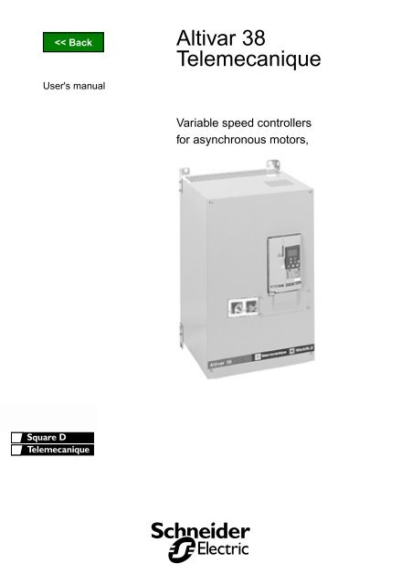
<strong>Altivar</strong> <strong>38</strong><br />
Telemecanique<br />
User's <strong>manual</strong><br />
Variable <strong>speed</strong> controllers<br />
for asynchronous motors,
<strong>Altivar</strong> <strong>38</strong><br />
FRANÇAIS ENGLISH DEUTSCH ESPAÑOL ITALIANO<br />
2
When the <strong>drive</strong> is powered up, the power components and some of the control components are<br />
connected to the line supply. It is extremely dangerous to touch them. The <strong>drive</strong> cover must be kept<br />
closed.<br />
CAUTION<br />
locking system is not sufficient: fit a cut-off on the power circuit.<br />
After the ALTIVAR has been switched off and the green LED has gone out, wait for 3 to 10 minutes before<br />
working on the equipment. This is the time required for the capacitors to discharge.<br />
The motor can be stopped during operation by inhibiting run commands or the <strong>speed</strong> reference while the<br />
<strong>drive</strong> remains powered up. If personnel safety requires prevention of sudden restarts, this electronic<br />
ENGLISH<br />
The <strong>drive</strong> is fitted with safety devices which, in the event of a fault, can shut down the <strong>drive</strong> and<br />
consequently the motor. The motor itself may be stopped by a mechanical blockage. Finally, voltage<br />
variations, especially line supply failures, can also cause shutdowns.<br />
NOTE<br />
If the cause of the shutdown disappears, there is a risk of restarting which may endanger certain<br />
machines or installations, especially those which must conform to safety regulations.<br />
In this case the user must take precautions against the possibility of restarts, in particular by using a low<br />
<strong>speed</strong> detector to cut off power to the <strong>drive</strong> if the motor performs an unprogrammed shutdown.<br />
Equipment should be designed in accordance with the specifications laid down in the IEC standards.<br />
As a rule, the <strong>drive</strong> power supply must be disconnected before any operation on either the electrical or<br />
mechanical parts of the installation or machine.<br />
The products and equipment described in this document may be changed or modified at any time, either<br />
from a technical point of view or in the way they are operated. Their description can in no way be<br />
considered contractual.<br />
The <strong>Altivar</strong> <strong>38</strong> must be considered as a component: it is neither a machine nor a device ready for use in<br />
accordance with European directives (machinery directive and electromagnetic compatibility directive).<br />
It is the responsibility of the end user to ensure that the machine meets these standards.<br />
CAUTION<br />
The specifications contained in this document must be applied in order to comply with the essential<br />
The <strong>drive</strong> must be installed and set up in accordance with both international and national standards.<br />
Bringing the device into conformity is the responsibility of the systems integrator who must observe the<br />
EMC directive among others within the European Union.<br />
requirements of the EMC directive.<br />
67
Contents<br />
Preliminary Recommendations _____________________________________________________ 68<br />
Selecting a Drive with Heatsink _____________________________________________________ 69<br />
Available Torque ________________________________________________________________ 70<br />
Technical Specifications ___________________________________________________________ 71<br />
Dimensions - Fan output __________________________________________________________ 73<br />
Mounting and Temperature Conditions _______________________________________________ 74<br />
Removing the IP 41 Protective Blanking Cover _________________________________________ 76<br />
Mounting in a Wall-fixing or Floor-standing Enclosure ____________________________________ 77<br />
Access to Terminals - Power Terminals _______________________________________________ 78<br />
Control Terminals ________________________________________________________________ 80<br />
Electromagnetic Compatibility - Wiring _______________________________________________ 81<br />
Wiring Recommendations, Use _____________________________________________________ 83<br />
Connection Diagrams _____________________________________________________________ 84<br />
Keypad operation ________________________________________________________________ 87<br />
Access to Menus ________________________________________________________________ 88<br />
Access to Menus - Programming Principle ____________________________________________ 89<br />
Macro-Configurations _____________________________________________________________ 90<br />
Display Menu ___________________________________________________________________ 91<br />
Adjust Menu ____________________________________________________________________ 92<br />
Drive Menu _____________________________________________________________________ 95<br />
Control Menu ___________________________________________________________________ 98<br />
I/O Menu _____________________________________________________________________ 101<br />
Configurable I/O Application Functions ______________________________________________ 105<br />
Fault Menu ____________________________________________________________________ 114<br />
Files Menu ____________________________________________________________________ 116<br />
Communication and Application Menus / Return to factory settings ________________________ 118<br />
Operation - Maintenance - Spares and Repairs ________________________________________ 119<br />
Faults - causes - remedies ________________________________________________________ 120<br />
Record of configuration and adjustments _____________________________________________ 123<br />
Summary of menus _____________________________________________________________ 125<br />
Index ________________________________________________________________________ 128<br />
ENGLISH<br />
68
Preliminary Recommendations<br />
Acceptance<br />
Check that the <strong>drive</strong> reference printed on the label is the same as that on the delivery note<br />
corresponding to the purchase order.<br />
Remove the <strong>Altivar</strong> <strong>38</strong> from its packaging and check that it has not been damaged in transit.<br />
Handling and storage<br />
To ensure the <strong>drive</strong> is protected before installation, handle and store the device in its packaging.<br />
Handling on installation<br />
The <strong>Altivar</strong> <strong>38</strong> range comprises 9 sizes of device, with various weights and dimensions.<br />
ENGLISH<br />
Small <strong>drive</strong>s can be removed from their packaging and installed without a handling device.<br />
A hoist must be used with large <strong>drive</strong>s; for this reason they are supplied with 4 handling "lugs". The precautions<br />
described below must be observed:<br />
45¡<br />
max.<br />
69
Selecting a Drive with Heatsink<br />
Three-phase supply voltage: <strong>38</strong>0...460 V 50/60 Hz<br />
Line current at<br />
400 V<br />
Isc<br />
prospective<br />
line<br />
Motor<br />
power<br />
(2)<br />
Nominal Max. transient<br />
current (In) current<br />
(3)<br />
Power dissipated<br />
at nominal load (4)<br />
Reference<br />
(5)<br />
Weight<br />
A kA kW A A W kg<br />
3.1 5 0.75 2.1 2.3 55 ATV<strong>38</strong>HU18N4 3.8<br />
5.4 5 1.5 3.7 4.1 65 ATV<strong>38</strong>HU29N4 3.8<br />
7.3 5 2.2 5.4 6 105 ATV<strong>38</strong>HU41N4 3.8<br />
10 5 3 7.1 7.8 145 ATV<strong>38</strong>HU54N4 6.9<br />
12.3 5 4 9.5 10.5 180 ATV<strong>38</strong>HU72N4 6.9<br />
16.3 5 5.5 11.8 13 220 ATV<strong>38</strong>HU90N4 6.9<br />
24.3 22 7.5 16 17.6 230 ATV<strong>38</strong>HD12N4 13<br />
33.5 22 11 22 24.2 340 ATV<strong>38</strong>HD16N4 13<br />
43.2 22 15 30 33 410 ATV<strong>38</strong>HD23N4 15<br />
42 22 18.5 37 41 670 ATV<strong>38</strong>HD25N4(X) 34<br />
49 22 22 44 49 750 ATV<strong>38</strong>HD28N4(X) 34<br />
65 22 30 60 66 925 ATV<strong>38</strong>HD33N4(X) 34<br />
79 22 37 72 80 1040 ATV<strong>38</strong>HD46N4(X) 34<br />
95 22 45 85 94 1045 ATV<strong>38</strong>HD54N4(X) 57<br />
118 22 55 105 116 1265 ATV<strong>38</strong>HD64N4(X) 57<br />
158 22 75 1<strong>38</strong> 152 1730 ATV<strong>38</strong>HD79N4(X) 57<br />
156 (1) 22 90 173 190 2250 ATV<strong>38</strong>HC10N4X 49<br />
191 (1) 22 110 211 232 2750 ATV<strong>38</strong>HC13N4X 75<br />
229 (1) 22 132 253 278 3300 ATV<strong>38</strong>HC15N4X 77<br />
279 (1) 22 160 300 330 4000 ATV<strong>38</strong>HC19N4X 77<br />
347 (1) 22 200 370 407 5000 ATV<strong>38</strong>HC23N4X 159<br />
<strong>38</strong>4 (1) 22 220 407 448 5500 ATV<strong>38</strong>HC25N4X 166<br />
433 (1) 22 250 450 495 6250 ATV<strong>38</strong>HC28N4X 168<br />
485 (1) 22 280 503 553 7000 ATV<strong>38</strong>HC31N4X 168<br />
536 (1) 22 315 564 620 7875 ATV<strong>38</strong>HC33N4X 168<br />
ENGLISH<br />
(4) Current values given with an additional line choke.<br />
(5) These power levels are for a maximum switching frequency of 2 or 4 kHz, depending on the rating, and<br />
continuous operation. Switching frequencies are detailed in the section on "Technical Specifications".<br />
Using the ATV<strong>38</strong> with a higher switching frequency:<br />
• For continuous operation derate by one power rating, for example:<br />
ATV<strong>38</strong>HU18N4 for 0.37 kW – ATV<strong>38</strong>HD12N4 for 5.5 kW.<br />
• If no power derating is applied, do not exceed the following operating conditions:<br />
Cumulative running time 36 s maximum per 60 s cycle (load factor 60%).<br />
(6) For 60 seconds.<br />
(7) These power levels are given for the maximum permissible switching frequency in continuous operation (2<br />
or 4 kHz, depending on the rating).<br />
(8) For ATV<strong>38</strong>HU18N4 to D79N4: the <strong>Altivar</strong> <strong>38</strong> is fitted with an integral EMC filter.<br />
For ATV<strong>38</strong>HD25N4(X) to D79N4(X): add X to the reference to receive an <strong>Altivar</strong> <strong>38</strong> without integral EMC<br />
filter.<br />
For ATV<strong>38</strong>HC10N4X to C33N4X: the <strong>Altivar</strong> <strong>38</strong> is not fitted with an integral EMC filter. Optional external<br />
filters are available.<br />
70
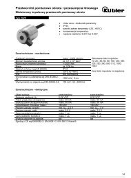
Available Torque<br />
Torque characteristics:<br />
• Variable torque applications:<br />
T/Tn<br />
1.1<br />
1<br />
0.95<br />
0.5<br />
3<br />
2 2<br />
1<br />
1<br />
4<br />
ENGLISH<br />
0 N (Hz)<br />
5<br />
25<br />
50<br />
75<br />
100<br />
30<br />
60<br />
90<br />
120<br />
1 Self-cooled motor: permanent useful torque<br />
2 Force-cooled motor: permanent useful torque<br />
3 Transient overtorque for max. 60 seconds.<br />
4 Torque at over<strong>speed</strong> with constant power<br />
Available overtorque:<br />
Variable torque applications:<br />
• 110% of the nominal motor torque for 60 seconds.<br />
Continuous operation<br />
For self-cooled motors, cooling is linked to the motor <strong>speed</strong>. Derating therefore occurs at <strong>speed</strong>s of less than<br />
half the nominal <strong>speed</strong>.<br />
Over<strong>speed</strong> operation<br />
As the voltage can no longer change with the frequency, induction in the motor is reduced which results in a<br />
reduction in torque. Check with the manufacturer that the motor can operate at over<strong>speed</strong>.<br />
Note: With a special motor, the nominal and maximum frequencies can be adjusted between 10 and 500 Hz<br />
using the operator terminal or PowerSuite tools.<br />
71
Technical Specifications<br />
Environment<br />
ATV<strong>38</strong> HU18N4 to ATV<strong>38</strong>HD23N4<br />
ATV<strong>38</strong> HD25N4(X) to ATV<strong>38</strong>HC33N4X<br />
Degree of<br />
protection<br />
IP21 and IP41 on upper part (conforming<br />
to EN 50178)<br />
ATV<strong>38</strong>HD25N4(X) to ATV<strong>38</strong>HD79N4(X)<br />
<strong>drive</strong>s:<br />
IP21 and IP41 on upper part (conforming<br />
to EN 50178)<br />
ATV<strong>38</strong>HC10N4X to ATV<strong>38</strong>HC33N4X<br />
<strong>drive</strong>s:<br />
- IP00 on underside (requires addition of<br />
protection against direct contact by<br />
personnel)<br />
- IP20 on other sides<br />
Vibration<br />
resistance<br />
Conforming to IEC 68-2-6:<br />
1.5 mm peak from 2 to 13 Hz<br />
1 gn from 13 to 200 Hz<br />
ATV<strong>38</strong>HD25N4(X) to ATV<strong>38</strong>HD79N4(X)<br />
<strong>drive</strong>s:<br />
Conforming to IEC 68-2-6:<br />
1.5 mm peak from 2 to 13 Hz<br />
1 gn from 13 to 200 Hz<br />
ENGLISH<br />
Maximum ambient<br />
pollution<br />
Maximum relative<br />
humidity<br />
Ambient<br />
temperature<br />
around the unit<br />
Maximum<br />
operating altitude<br />
Operating position<br />
ATV<strong>38</strong>HU18N4 to ATV<strong>38</strong> HD23N4<br />
<strong>drive</strong>s:<br />
Degree 2 conforming to IEC 664-1 and<br />
EN 50718<br />
ATV<strong>38</strong>HC10N4X to ATV<strong>38</strong>HC33N4X<br />
<strong>drive</strong>s:<br />
0.6 gn from 10 to 55 Hz<br />
ATV<strong>38</strong>HD25N4(X) to ATV<strong>38</strong>HD79N4(X)<br />
<strong>drive</strong>s:<br />
- Degree 3 conforming to UL508C<br />
ATV<strong>38</strong>HC10N4X to ATV<strong>38</strong> HC33N4X<br />
<strong>drive</strong>s:<br />
Degree 2 conforming to IEC 664-1 and<br />
EN 50718<br />
93% without condensation or dripping water, conforming to IEC 68-2-3<br />
Storage: -25 ˚C to +65 ˚C<br />
Operation:<br />
ATV<strong>38</strong>HU18N4 to ATV<strong>38</strong>HU90N4<br />
<strong>drive</strong>s:<br />
• -10 ˚C to +50 ˚C without derating<br />
• up to +60 ˚C with current derating of<br />
2.2% per ˚C above 50 ˚C<br />
ATV<strong>38</strong>HD12N4 to ATV<strong>38</strong>HD23N4<br />
<strong>drive</strong>s:<br />
• -10 ˚C to +40 ˚C without derating<br />
• up to +50 ˚C with current derating of<br />
2.2% per ˚C above 40 ˚C<br />
Storage: -25 ˚C to +65 ˚C<br />
Operation:<br />
ATV<strong>38</strong>HD25N4(X) to ATV<strong>38</strong>HD79N4(X)<br />
<strong>drive</strong>s:<br />
• -10 ˚C to +40 ˚C without derating<br />
• up to +60 ˚C with the ventilation kit<br />
with current derating of 2.2% per ˚C<br />
above 40 ˚C<br />
ATV<strong>38</strong>HC10N4X to ATV<strong>38</strong>HC33N4X<br />
<strong>drive</strong>s:<br />
• -10 ˚C to +40 ˚C without derating<br />
• up to +50 ˚C with current derating of<br />
2.2% per ˚C above 40 ˚C<br />
1000 m without derating (above this, derate the current by 1% per additional 100 m)<br />
Vertical<br />
72
Technical Specifications<br />
Electrical characteristics<br />
ENGLISH<br />
Power Voltage • <strong>38</strong>0 V - 10% to 460 V + 10% 3-phase<br />
supply<br />
Frequency • 50/60 Hz ± 5%<br />
Output voltage<br />
Maximum voltage equal to line supply voltage<br />
Electrical isolation<br />
Electrical isolation between power and control (inputs, outputs, power<br />
supplies)<br />
Output frequency range 0.1 to 500 Hz<br />
Switching frequency Configurable:<br />
• without derating:<br />
0.5 - 1 - 2 - 4 kHz for ATV<strong>38</strong>HU18N4 to D46N4(X) <strong>drive</strong>s<br />
0.5 - 1 - 2 kHz for ATV<strong>38</strong>HD54N4(X) to C33N4X <strong>drive</strong>s<br />
• without derating with intermittent operating cycle<br />
or with derating by one power rating in continuous operation:<br />
8 - 12 - 16 kHz for ATV<strong>38</strong>HU18N4 to D23N4 <strong>drive</strong>s<br />
8 - 12 kHz for ATV<strong>38</strong>HD25N4(X) to D46N4(X) <strong>drive</strong>s<br />
4 - 8 kHz for ATV<strong>38</strong>HD54N4(X) to D79N4(X) <strong>drive</strong>s<br />
4 kHz for ATV<strong>38</strong>HC10N4X to C33N4X <strong>drive</strong>s<br />
Speed range 1 to 10<br />
Braking torque<br />
30% of nominal motor torque without braking resistor (typical value) for low<br />
power ratings<br />
Transient overtorque 110% of nominal motor torque (typical values to ±10%) for 60 seconds<br />
Protection and safety<br />
features of <strong>drive</strong><br />
• Short-circuit protection:<br />
- between output phases<br />
- between output phases and earth<br />
- on internal supply outputs<br />
• Thermal protection against overheating and overcurrents<br />
• Supply undervoltage and overvoltage safety circuits<br />
• Loss of input phase safety circuit (avoids single-phase operation, on all 3-<br />
phase <strong>drive</strong>s)<br />
Motor protection • Thermal protection integrated in <strong>drive</strong> via continuous calculation of I 2 t<br />
taking <strong>speed</strong> into account<br />
Motor thermal state saved when the <strong>drive</strong> is switched off. This function can<br />
be modified (via the operator terminal or programming terminal or via the<br />
PC software), depending on the type of motor cooling<br />
• Protection against motor phase breaks<br />
• Protection via PTC probes with option card<br />
73
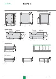
Dimensions - Fan output<br />
Dimensions<br />
c<br />
b<br />
¯1<br />
= G =<br />
a<br />
= H<br />
=<br />
Db<br />
View A<br />
3 screws<br />
Ø 2 tapped holes for fixing the EMC<br />
A<br />
clamp.<br />
The EMC mounting plate is supplied with clamps for<br />
ATV<strong>38</strong>HU18N4 to D79N4(X) <strong>drive</strong>s. Fix the EMC<br />
equipotentiality mounting plate to the holes in the ATV<strong>38</strong><br />
heatsink using the screws supplied, as shown in the drawings<br />
above.<br />
ENGLISH<br />
EMC mounting plate<br />
ATV<strong>38</strong>H a b c G H Ø1 ∆ b Ø2<br />
U18N4, U29N4, U41N4 150 230 184 133 210 5 64.5 4<br />
U54N4, U72N4, U90N4 175 286 184 155 270 5.5 64.5 4<br />
D12N4, D16N4 230 325 210 200 310 5.5 76 4<br />
D23N4 230 415 210 200 400 5.5 76 4<br />
D25N4(X), D28N4(X), D33N4(X), 240 550 283 205 530 7 80 5<br />
D46N4(X)<br />
D54N4(X), D64N4(X), D79N4(X) 350 650 304 300 619 9 110 5<br />
C10N4X 370 630 360 317.5 609 12<br />
C13N4X, C15N4X, C19N4X 480 680 400 426 652 12<br />
C23N4X, C25N4X, C28N4X,<br />
C31N4X,C33N4X<br />
660 950 440 598 920 15<br />
Fan output<br />
ATV<strong>38</strong>HU18N4<br />
ATV<strong>38</strong>HU29N4, U41N4, U54N4<br />
ATV<strong>38</strong>HU72N4, U90N4, D12N4,D16N4, D23N4<br />
ATV<strong>38</strong>HD25N4(X), HD28N4(X), D33N4(X), D46N4(X)<br />
ATV<strong>38</strong>HD54N4(X), D64N4(X), D79N4(X)<br />
ATV<strong>38</strong>HC10N4X<br />
ATV<strong>38</strong>HC13N4X, C15N4X, C19N4X<br />
ATV<strong>38</strong>HC23N4X, C25N4X, C28N4X, C31N4X,C33N4X<br />
not cooled<br />
36 m 3 /hour<br />
72 m 3 /hour<br />
292 m 3 /hour<br />
492 m 3 /hour<br />
600 m 3 /hour<br />
900 m 3 /hour<br />
900 m 3 /hour<br />
74
Mounting and Temperature Conditions<br />
Install the unit vertically to within +/-10 °.<br />
Do not place it close to heating elements.<br />
Leave sufficient free space to ensure that the air required for cooling purposes can circulate from the bottom<br />
to the top of the unit.<br />
ATV<strong>38</strong>HU18N4 to D23N4<br />
³ 50<br />
Free space in front of unit: 10 mm minimum.<br />
ENGLISH<br />
³ d ³ d<br />
³ 50<br />
ATV<strong>38</strong>HU18N4 to U90N4:<br />
From - 10 °C to 40 °C: d ≥ 50 mm: no special precautions.<br />
d = 0: remove the protective blanking cover from the top of the <strong>drive</strong> as shown overleaf<br />
(the degree of protection is then IP 20).<br />
From 40 °C to 50 °C:<br />
d ≥ 50 mm: remove the protective blanking cover from the top of the <strong>drive</strong> as shown<br />
overleaf (the degree of protection is then IP 20).<br />
d = 0: add control ventilation kit VW3A5882• (see ATV<strong>38</strong> catalogue).<br />
From 50 °C to 60 °C:<br />
d ≥ 50 mm: add control ventilation kit VW3A5882• (see ATV<strong>38</strong> catalogue).<br />
Derate the operating current by 2.2% per °C over 50 °C.<br />
ATV<strong>38</strong>HD12N4 to D23N4:<br />
From - 10 °C to 40 °C: d ≥ 50 mm: no special precautions.<br />
d = 0: remove the protective blanking cover from the top of the <strong>drive</strong> as shown overleaf<br />
(the degree of protection is then IP 20).<br />
From 40 °C to 50 °C:<br />
d ≥ 50 mm: remove the protective blanking cover from the top of the <strong>drive</strong> as shown<br />
overleaf (the degree of protection is then IP 20).<br />
Derate the current by 2.2% per °C over 40 °C.<br />
d = 0: add control ventilation kit VW3A5882 (see ATV<strong>38</strong> catalogue). Derate the current<br />
by 2.2% per °C over 40 °C.<br />
75
Mounting and Temperature Conditions<br />
ATV<strong>38</strong>HD25N4(X) to D79N4(X)<br />
³ 100<br />
• Free space in front of unit: 50 mm minimum.<br />
• From - 10 °C to 40 °C: no special precautions.<br />
• From 40 °C to 60 °C: add control ventilation kit VW3A588••• (see<br />
ATV<strong>38</strong> catalogue). Derate the current by 2.2% per °C over 40 °C.<br />
³ 50 ³ 50<br />
ENGLISH<br />
³ 100<br />
ATV<strong>38</strong>HC10N4X to C23N4X<br />
³ 200<br />
• Free space in front of unit: 50 mm minimum.<br />
• From - 10 °C to 40 °C: no special precautions.<br />
• Up to 50 °C, derating the operating current by 2.2% for each °C<br />
above 40 °C.<br />
³ 50 ³ 50<br />
³ 200<br />
76
Removing the IP 41 Protective Blanking Cover<br />
ATV<strong>38</strong>HU18N4 to U90N4<br />
ENGLISH<br />
ATV<strong>38</strong>HD12N4 to D23N4<br />
ATV<strong>38</strong>HD25N4(X) to D79N4(X)<br />
77
Mounting in a Wall-fixing or Floor-standing<br />
Enclosure<br />
Observe the mounting recommendations on the previous page.<br />
To ensure proper air circulation in the <strong>drive</strong>:<br />
- Fit ventilation grilles<br />
- Ensure that ventilation is adequate: if not, install<br />
forced ventilation with a filter<br />
- Use special IP 54 filters<br />
Dust and damp proof metal wall-fixing or floor-standing<br />
enclosure (IP 54 degree of protection)<br />
The <strong>drive</strong> must be mounted in a dust and damp proof casing in certain environmental conditions: dust,<br />
corrosive gases, high humidity with risk of condensation and dripping water, splashing liquid, etc.<br />
ENGLISH<br />
To avoid hot spots in the <strong>drive</strong>, add a fan to circulate the air inside the enclosure, reference VW3A5882• (see<br />
ATV<strong>38</strong> catalogue).<br />
This enables the <strong>drive</strong> to be used in an enclosure where the maximum internal temperature can reach 60 °C.<br />
Calculating the size of the enclosure<br />
Maximum thermal resistance Rth (°C/W) :<br />
Rth =<br />
θ° - θ°e<br />
P<br />
θ° = maximum temperature inside enclosure in °C<br />
θ°e = maximum external temperature in °C<br />
P = total power dissipated in the enclosure in W<br />
Power dissipated by the <strong>drive</strong>: see section Selecting a <strong>drive</strong>.<br />
Add the power dissipated by the other equipment components.<br />
Useful heat dissipation surface of enclosure S (m 2 ):<br />
(sides + top + front panel if wall-mounted)<br />
S =<br />
K<br />
Rth<br />
K = enclosure thermal resistance per m 2<br />
For metal enclosure:<br />
K = 0.12 with internal fan<br />
K = 0.15 without fan<br />
Caution: Do not use insulated enclosures, as they have a poor level of conductivity.<br />
78
Access to Terminals - Power Terminals<br />
Access to terminals<br />
Switch off the <strong>drive</strong>.<br />
ATV<strong>38</strong>HU18N4 to ATV<strong>38</strong>HD79N4(X):<br />
- control terminals: unlock and open the hinged cover<br />
- power terminals: accessible on the underside of the <strong>Altivar</strong> <strong>38</strong><br />
Location of terminals: on the underside of the <strong>Altivar</strong>.<br />
1<br />
2<br />
1 Control<br />
2 Power<br />
3 Terminal for connection of a protective conductor,<br />
10 mm 2 cross-section conforming to EN50178<br />
(earth leakage current)<br />
ENGLISH<br />
ATV<strong>38</strong>HC10N4X to HC33N4X:<br />
- the control and power terminals can be accessed by removing the front cover<br />
Power terminals<br />
3<br />
Terminal characteristics<br />
<strong>Altivar</strong> ATV<strong>38</strong>H Terminals Maximum connection capacity Tightening<br />
AWG mm 2 torque in Nm<br />
U18N4, U29N4, U41N4 all terminals AWG 8 6 0.75<br />
U54N4, U72N4, U90N4 all terminals AWG 8 6 0.75<br />
D12N4, D16N4, D23N4 all terminals AWG 6 10 2<br />
D25N4(X), D28N4(X) L1, L2, L3, U, V, W, AWG 4 16 3<br />
D33N4(X), D46N4(X) L1, L2, L3, U, V, W, AWG 2 35 4<br />
D54N4(X), D64N4(X), L1, L2, L3, U, V, W, AWG 2/0 70 10<br />
D79N4(X)<br />
C10N4X AWG 3/0 60 8<br />
other terminals AWG 3/0 100 16<br />
C13N4X AWG 4/0 60 16<br />
other terminals AWG 4/0 100 16<br />
C15N4X AWG 1/0 x 2 60 16<br />
other terminals AWG 1/0 x 2 100 16<br />
C19N4X AWG 3/0 x 2 100 16<br />
other terminals AWG 3/0 x 2 150 16<br />
C23N4X AWG 4/0 x 2 100 32<br />
other terminals AWG 4/0 x 2 200 32<br />
79
Power Terminals<br />
<strong>Altivar</strong> ATV<strong>38</strong>H Terminals Maximum connection capacity Tightening<br />
torque in Nm<br />
AWG mm 2<br />
C25N4X AWG 2/0 x 3 - AWG 300 x 2 100 32<br />
other terminals AWG 2/0 x 3 - AWG 300 x 2 200 32<br />
C28N4X AWG 3/0 x 3 - AWG 350 x 2 150 32<br />
other terminals AWG 3/0 x 3 - AWG 350 x 2 150 x 2 32<br />
C31N4X, AWG 4/0 x 3 - AWG 400 x 2 150 32<br />
other terminals AWG 4/0 x 3 - AWG 400 x 2 150 x 2 32<br />
C33N4X AWG 250 x 3 - AWG 500 x 2 150 32<br />
other terminals AWG 250 x 3 - AWG 500 x 2 150 x 2 32<br />
Terminal layout<br />
L1 L2 L3 PA PB U V W<br />
ATV<strong>38</strong>HU18N4 to D23N4<br />
ENGLISH<br />
L1 L2 L3 + - PA PB U V W<br />
ATV<strong>38</strong>HD25N4(X) and D79N4(X)<br />
L1 L2 L3<br />
+ + -<br />
U V W<br />
ATV<strong>38</strong>HC10N4X<br />
L1<br />
L2<br />
L3<br />
+ -<br />
U V W<br />
ATV<strong>38</strong>HC13N4X to C19N4X<br />
L1 L2 L3<br />
-<br />
+ + U V W<br />
ATV<strong>38</strong>HC23N4X to C33N4X<br />
Do not use<br />
Terminal functions<br />
Terminals Function For <strong>Altivar</strong> ATV<strong>38</strong>H<br />
<strong>Altivar</strong> ground terminal<br />
All ratings<br />
L1<br />
L2<br />
L3<br />
Power supply<br />
All ratings<br />
+<br />
–<br />
PA<br />
PB<br />
U<br />
V<br />
W<br />
DC bus outputs<br />
Not used<br />
Outputs to motor<br />
All ratings<br />
except HU18N4 to HD23N4<br />
ATV<strong>38</strong>HU18N4 to HD79N4(X)<br />
All ratings<br />
80
Control Terminals<br />
Terminal characteristics:<br />
• Shielding connection terminal: for metal clamp or tag connector<br />
• 2 removable terminals, one for the relay contacts, the other for the low-level I/O<br />
• Maximum connection capacity : 1.5 mm 2 - AWG 14<br />
• Max. tightening torque: 0.4 Nm<br />
Terminal layout:<br />
Control card<br />
ENGLISH<br />
R1A<br />
R1B<br />
R1C<br />
R2A<br />
R2C<br />
A01 AO1<br />
COM<br />
AI 1<br />
+10<br />
AI 2<br />
LI 1<br />
LI 2<br />
LI 3<br />
LI 4<br />
+24<br />
Terminal functions<br />
Terminal Function Electrical characteristics<br />
R1A<br />
R1B<br />
R1C<br />
R2A<br />
R2C<br />
Common point C/O contact (R1C)<br />
of R1 fault relay<br />
N/O contact of R2 programmable<br />
relay<br />
Min. switching capacity<br />
• 10 mA for 24 Va<br />
Max. switching capacity on inductive load<br />
(cos ϕ 0.4 and L/R 7 ms):<br />
• 1.5 A for 250 Vc and 30 Va<br />
AO1 Analog current output X-Y mA analog output, where X and Y can be configured<br />
Factory setting 0 - 20 mA<br />
impedance 500 Ω<br />
COM Common for logic and analog<br />
inputs<br />
AI1 Analog voltage input Analog input 0 + 10 V<br />
impedance 30 kΩ<br />
+10 Power supply for reference<br />
potentiometer 1 to 10 kΩ<br />
+10 V (- 0, + 10%) 10 mA max.<br />
short-circuit and overload protection<br />
AI2 Analog current input X-Y mA analog input, where X and Y can be configured<br />
Factory setting 4 - 20 mA<br />
impedance 100 Ω<br />
LI1<br />
LI2<br />
LI3<br />
LI4<br />
Logic inputs<br />
Programmable logic inputs<br />
impedance 3.5 kΩ<br />
+ 24 V power supply (max. 30 V)<br />
State 0 if < 5 V, state 1 if > 11 V<br />
+ 24 Power supply for inputs + 24 V protected against short-circuits and overloads,<br />
min. 18 V, max. 30 V<br />
Max. current 200 mA<br />
81
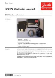
Electromagnetic Compatibility - Wiring<br />
<strong>Altivar</strong> <strong>38</strong> with integral EMC filter ATV<strong>38</strong>HU18N4 to HD79N4<br />
Principle<br />
• Grounds between <strong>drive</strong>, motor and cable shielding must have "high frequency" equipotentiality.<br />
• Use shielded cables with shielding connected to the ground at both ends of the motor cable, braking resistor<br />
(if fitted) and control-signalling cables. Conduit or metal ducting can be used for part of the shielding length<br />
provided that there is no break in continuity.<br />
• Ensure maximum separation between the power supply cable (line supply) and the motor cable.<br />
Installation diagram<br />
2<br />
ENGLISH<br />
7<br />
4<br />
1<br />
3<br />
5<br />
8 6<br />
1 Sheet steel machine ground supplied with the <strong>drive</strong>, to be fitted as indicated on the diagram.<br />
2 <strong>Altivar</strong> <strong>38</strong>.<br />
3 Non-shielded power supply wires or cable.<br />
4 Non-shielded wires for the output of the safety relay contacts.<br />
5 Fix and ground the shielding of cables 6, 7 and 8 as close as possible to the <strong>drive</strong>:<br />
- strip the cable to expose the shielding<br />
- use the clamps supplied to fix the stripped part of the shielding to the metal plate 1<br />
The shielding must be clamped tightly enough to the metal plate to ensure good contact.<br />
6 Shielded cable for motor connection with shielding connected to ground at both ends.<br />
The shielding must be continuous and intermediate terminals must be in EMC shielded metal boxes.<br />
7 Shielded cable for connecting the control/signalling wiring.<br />
For applications requiring several conductors, use small cross-sections (0.5 mm 2 ).<br />
The shielding must be connected to ground at both ends. The shielding must be continuous and<br />
intermediate terminals must be in EMC shielded metal boxes.<br />
8 Shielded cable for connecting braking resistor (if fitted). The shielding must be connected to ground at both<br />
ends. The shielding must be continuous and intermediate terminals must be in EMC shielded metal boxes.<br />
Note:<br />
• If using an additional input filter, it should be mounted behind the <strong>drive</strong> and connected directly to the line<br />
supply via an unshielded cable. Link 3 to the <strong>drive</strong> is then via the filter output cable.<br />
• The HF equipotential ground connection between the <strong>drive</strong>, motor and cable shielding does not remove the<br />
need to connect the PE protective conductors (green-yellow) to the appropriate terminals on each unit.<br />
82
Electromagnetic Compatibility - Wiring<br />
<strong>Altivar</strong> <strong>38</strong> without integral EMC filter ATV<strong>38</strong>HC10N4X to<br />
HC33N4X<br />
Line chokes are compulsory if the line supply prospective short-circuit current is less than 22 kA. These chokes<br />
can be used to provide improved protection against overvoltages on the line supply and to reduce harmonic<br />
distortion of the current produced by the <strong>drive</strong>. The chokes are used to limit the line current.<br />
ENGLISH<br />
Principle<br />
• Grounds between <strong>drive</strong>, motor and cable shielding must have "high frequency" equipotentiality.<br />
• Use shielded cables with shielding connected to the ground at both ends of the motor cable, and controlsignalling<br />
cables. Conduit or metal ducting can be used for part of the shielding length provided that there<br />
is no break in continuity.<br />
• Ensure maximum separation between the power supply cable (line supply) and the motor cable.<br />
Power wiring<br />
The power wiring should consist of cables with 4 conductors or individual cables maintained as close as<br />
possible to the PE cable. Take care to route the motor cables well away from the power supply cables.<br />
The power supply cables are not shielded. If a radio interference filter is used, the grounds for the filter and the<br />
<strong>drive</strong> should be at the same potential with low-impedance links at high frequency (fixed to unpainted metal<br />
plate with anti-corrosion treatment/machine ground wiring). The filter should be fitted as close as possible to<br />
the <strong>drive</strong>.<br />
If the environment is sensitive to radiated radio interference, the motor cables should be shielded. On the <strong>drive</strong><br />
side, fix and connect the shielding to the machine ground with rustproof clamps. The main function of the motor<br />
cable shielding is to limit their radio frequency radiation. Therefore, use 4-pole cables for the motor, connecting<br />
each end of the shielding in accordance with established practice for High Frequency wiring. The type of<br />
protective material (copper or steel) is less important than the quality of the connection at both ends. An<br />
alternative is to use a metal cable duct with good conductivity and no break in continuity.<br />
Note: when using a cable with a protective sleeve (NYCY type) which fulfils the dual function of PE + screen,<br />
it must be connected correctly to both the <strong>drive</strong> and the motor (its radiation efficiency is reduced).<br />
Control wiring<br />
Shielding clamp<br />
Cable grip. Check that the cable follows the path indicated<br />
by the clips<br />
83
Wiring Recommendations, Use<br />
Wiring recommendations<br />
Power<br />
Observe the cable cross-sectional areas recommended in the standards.<br />
The <strong>drive</strong> must be earthed to conform with the regulations concerning high leakage currents (over 3.5 mA). Do<br />
not use a residual current device for upstream protection on account of the DC elements which may be<br />
generated by leakage currents. If the installation involves several <strong>drive</strong>s on the same line, each <strong>drive</strong> must be<br />
earthed separately. If necessary, fit a line choke (consult the catalogue).<br />
Keep the power cables separate from circuits in the installation with low-level signals (detectors, PLCs,<br />
measuring apparatus, video, telephone).<br />
Control<br />
Keep the control circuits away from the power cables. For control and <strong>speed</strong> reference circuits, we recommend<br />
using shielded twisted cables with a pitch of between 25 and 50 mm connecting the shielding to each end.<br />
Recommendations for use<br />
With power switching via line contactor:<br />
ENGLISH<br />
- Avoid operating contactor KM1 frequently (premature ageing of the filter capacitors). Use<br />
inputs LI1 to LI4 to control the <strong>drive</strong><br />
- these steps are essential in the event of cycles:<br />
of less than 60 seconds for ATV<strong>38</strong>HU18N4 to HD79N4(X)<br />
of less than 180 seconds for ATV<strong>38</strong>HC10N4X to ATV<strong>38</strong>HC33N4X<br />
If safety standards necessitate isolation of the motor, fit a contactor on the <strong>drive</strong> output and use the<br />
"downstream contactor control" function (consult the programming <strong>manual</strong>).<br />
Fault relay, unlocking<br />
The fault relay is energized when the <strong>drive</strong> is powered up and is not faulty. It has one C/O contact at the<br />
common point.<br />
The <strong>drive</strong> is unlocked after a fault by:<br />
• powering down the <strong>drive</strong> until both the display and indicator lamps go out, then powering up again<br />
• automatically or remotely via logic input: consult the programming <strong>manual</strong><br />
84
Connection Diagrams<br />
3-phase power supply<br />
ÐQ1<br />
ENGLISH<br />
(2)<br />
(3)<br />
L1<br />
L2<br />
L3<br />
U<br />
V<br />
W<br />
R1A<br />
AO1<br />
R1C<br />
COM<br />
AI1<br />
+10<br />
AI2<br />
2<br />
4<br />
6<br />
1<br />
3<br />
5<br />
Without<br />
line<br />
contactor<br />
or<br />
With<br />
line<br />
contactor<br />
1 ÐQ22 ÐT1 1 ÐQ32<br />
ÐS2<br />
3 4 ÐQ2 5 6<br />
ÐS1<br />
Ð KM1<br />
A1 A2<br />
Ð KM1<br />
1<br />
3<br />
5<br />
A1<br />
Ð KM1<br />
R1A R1C 13 14<br />
(1)<br />
(4)<br />
A1<br />
2<br />
R1B<br />
4<br />
6<br />
LI1<br />
LI2<br />
LI3<br />
LI4<br />
+24<br />
R2A<br />
R2C<br />
U1<br />
V1<br />
W1<br />
M<br />
3 c<br />
X-YmA<br />
Motorfrequency<br />
Reference potentiometer<br />
X-YmA<br />
(1) ATV<strong>38</strong>HC10N4X to C33N4X: Line choke compulsory.<br />
ATV<strong>38</strong>HU18N4 to D23N4: Line choke if necessary.<br />
(2) Fault relay contacts for remote signalling of <strong>drive</strong> status.<br />
(3) Internal + 24 V. If an external + 24 V supply is used, connect the 0 V from that source to the COM terminal,<br />
do not use the + 24 terminal on the <strong>drive</strong>, and connect the common of the LI inputs to the + 24 V of the<br />
external supply.<br />
(4) R2 reassignable relay.<br />
Note:<br />
Fit interference suppressors to all inductive circuits near the <strong>drive</strong> or connected in the same circuit, such as<br />
relays, contactors, solenoid valves, fluorescent lighting, etc.<br />
Components which can be used in association with the <strong>Altivar</strong>: see catalogue.<br />
85
Connection diagrams<br />
Diagram with downstream contactor for ATV<strong>38</strong>HU18N4 to D23N4.<br />
The shaded part should be added to the various diagram types.<br />
A1<br />
U<br />
V<br />
U1<br />
W<br />
R2C<br />
Ð KM2<br />
1<br />
2<br />
3<br />
4<br />
5<br />
COM<br />
(0V)<br />
6<br />
R2A<br />
+24<br />
A2<br />
A1<br />
V1<br />
W1<br />
M<br />
3 c<br />
ENGLISH<br />
Use the "downstream contactor control" function with relay R2, or logic output LO (a 24 V) with the addition<br />
of an I/O extension card.<br />
Consult the programming <strong>manual</strong>.<br />
Note:<br />
Fit interference suppressors to all inductive circuits near the <strong>drive</strong> or connected in the same circuit, such as<br />
relays, contactors, solenoid valves, fluorescent lighting, etc.<br />
Components which can be used in association with the <strong>Altivar</strong>: see catalogue.<br />
86
Connection Diagrams<br />
Diagram with downstream contactor for ATV<strong>38</strong>HD25N4(X) to C33N4X.<br />
The shaded part should be added to the 3-phase power supply diagram.<br />
ÐQ1<br />
ENGLISH<br />
A1<br />
U<br />
V<br />
W<br />
R2C<br />
R2A<br />
Ð KM2<br />
U1<br />
V1<br />
W1<br />
1<br />
2<br />
3<br />
4<br />
5<br />
6<br />
2<br />
4<br />
6<br />
1<br />
3<br />
5<br />
ÐQ2 3 4<br />
ÐQ2 5 6<br />
ÐT1<br />
1 2<br />
ÐQ3<br />
1 2<br />
A1<br />
A2<br />
M<br />
3 c<br />
Use the "downstream contactor control" function with relay R2, or logic output LO (a24V) switching the coil<br />
using an I/O extension card.<br />
Consult the programming <strong>manual</strong>.<br />
Note: Fit interference suppressors to all inductive circuits near the <strong>drive</strong> or connected in the same circuit, such<br />
as relays, contactors, solenoid valves, fluorescent lighting, etc.<br />
Components which can be used in association with the <strong>Altivar</strong>: see catalogue.<br />
24 V external supply for supplying logic inputs<br />
A1<br />
0V<br />
+24V<br />
COM<br />
LI¥<br />
LI¥<br />
LI¥<br />
LI¥<br />
+24<br />
87
Keypad operation<br />
Front panel<br />
ESC<br />
ENT<br />
FWD<br />
REV<br />
LOC<br />
RUN<br />
PROG<br />
ESC<br />
ENT<br />
STOP<br />
RESET<br />
Scroll through menus or parameters and<br />
adjust a value.<br />
Return to the previous menu or abort the<br />
current adjustment and return to the<br />
original value.<br />
Select a menu, confirm and save a<br />
selection or adjustment.<br />
Use of keys and meaning of displays<br />
Â Ú Flashing:<br />
indicates the selected direction of rotation<br />
Steady:<br />
indicates the direction of motor rotation<br />
LOC Indicates control via the terminal<br />
PROG Appears in setup and programming mode<br />
Flashing:<br />
indicates that a value has been modified but not saved<br />
4-character display:<br />
displays numeric values and codes<br />
One line of 16 characters:<br />
displays messages in plain text<br />
If control via the terminal is active:<br />
FWD<br />
REV<br />
RUN<br />
STOP<br />
RESET<br />
Reverses the direction of rotation.<br />
Command to start the motor running.<br />
Command to stop the motor or reset the<br />
fault. The key’s "STOP" function can be<br />
inhibited via the program ("CONTROL"<br />
menu).<br />
ENGLISH<br />
Use the display module delivered with the ATV<strong>38</strong> or a version 5.1 or above display module<br />
(see label on the rear view).<br />
Rear view<br />
Notes:<br />
The operator terminal may be connected and disconnected with the<br />
power on. If the terminal is disconnected when control of the <strong>drive</strong> via<br />
the terminal is enabled, the <strong>drive</strong> locks in fault mode SLF.<br />
Access locking switch:<br />
- position : Adjustment and configuration not accessible<br />
- position : Adjustment accessible<br />
- position : Adjustment and configuration accessible<br />
Connector:<br />
- for direct connection of the terminal to the <strong>drive</strong><br />
- for remote operation, the terminal can be connected via a cable<br />
provided in the VW3A58103 kit<br />
Remote mounting of the terminal:<br />
Use the kit, reference VW3A58103, comprising 1 cable with<br />
connectors, the kit for mounting on an enclosure door and the<br />
installation guide.<br />
88
Access to Menus<br />
The number of menus which can be accessed depends on the position of the access locking switch.<br />
Each menu is made up of a number of parameters.<br />
1st<br />
power-up<br />
Subsequent<br />
power-ups<br />
Language: French, English, German, Spanish,<br />
Italian<br />
LnG<br />
LANGUAGE<br />
ESC<br />
access:<br />
Macro-config: <strong>variable</strong> torque (factory setting)<br />
If an input/output has been reassigned,<br />
CuS: Customised is displayed<br />
CFG<br />
MACRO-CONFIG<br />
or<br />
ENGLISH<br />
Identification: display of the <strong>drive</strong> power and<br />
voltage<br />
Display: display of electrical values, operation or<br />
fault<br />
rEF<br />
15 kW <strong>38</strong>0/460 V<br />
SUP<br />
1-DISPLAY<br />
or<br />
Adjust: configuration of parameters which<br />
can be accessed while the motor is rotating<br />
SEt<br />
2-ADJUST<br />
Drive: motor-<strong>drive</strong> configuration<br />
drC<br />
3-DRIVE<br />
Control: configuration of <strong>drive</strong> control:<br />
terminal strip, operator terminal, RS485<br />
CtL<br />
4-CONTROL<br />
I/O: configuration of the I/O assignment<br />
5-I/O<br />
I-O<br />
Faults: configuration of the behaviour of the<br />
motor-<strong>drive</strong> in the event of a fault, and the<br />
protection devices<br />
Files: saving and restoring the configuration<br />
or return to factory settings<br />
Only accessible if the "application" or<br />
"communication" card is installed<br />
APP<br />
8-APPLICATION<br />
FLt<br />
6-FAULT<br />
FLS<br />
7-FILES<br />
SL<br />
8-COMMUNICATION<br />
CAUTION: If an access code has already been programmed, it may be impossible to modify some menus;<br />
these may not even be visible. In this case, see the section entitled “FILES menu” explaining how to enter the<br />
access code.<br />
89
Access to Menus - Programming Principle<br />
Language:<br />
This menu can be accessed whatever position the access switch is in, and can be modified in stop or run mode.<br />
Example :<br />
LnG<br />
LANGUAGE<br />
ENT<br />
LnG<br />
English<br />
ESC<br />
Save the<br />
new selection<br />
ENT<br />
LnG<br />
Italiano<br />
LnG<br />
Italiano<br />
Return to previously<br />
saved selection<br />
ESC<br />
LnG<br />
English<br />
ENGLISH<br />
Possible selections: English (factory setting), French, German, Spanish, Italian.<br />
Programming principle:<br />
The principle is always the same, with 1 or 2 levels:<br />
• 1 level: see the “language” example above.<br />
• 2 levels: see the “acceleration ramp” example below.<br />
SEt<br />
2.ADJUST<br />
ENT<br />
ESC<br />
Acceleration<br />
ESC<br />
ACC<br />
ENT<br />
3.0<br />
s<br />
Acceleration s<br />
Increase (or Decrease)<br />
Save the<br />
new value<br />
Acceleration<br />
3.1<br />
s<br />
Return to previously<br />
saved value<br />
ENT<br />
Acceleration<br />
3.1<br />
s<br />
Acceleration<br />
ESC<br />
3.0<br />
s<br />
90
Macro-Configurations<br />
This parameter can always be displayed and indicates whether an input/output has been reassigned.<br />
Factory macro-configuration = Variable torque<br />
Customizing the configuration:<br />
The <strong>drive</strong> configuration can be customized by changing the I/O assignment in the I/O menu which can be<br />
accessed in programming mode (access switch in position ).<br />
This customization modifies the displayed macro-configuration value:<br />
display of<br />
CFG<br />
CUS:Customised<br />
I/O assignment in <strong>variable</strong> torque macro-configuration<br />
ENGLISH<br />
Logic input LI1 forward Logic input LI5 ramp switching<br />
Logic input LI2 reverse Logic input LI6 Not assigned<br />
Logic input LI3 Fault reset Analog input AI3 or summed ref.<br />
Logic input LI4 Not assigned Inputs A, A+, B, B+ summed ref.<br />
Analog input AI1 motor frequency Logic output LO high <strong>speed</strong> reached<br />
Analog input AI2 summed ref. Analog output AO motor current<br />
Relay R1<br />
<strong>drive</strong> fault<br />
Relay R2<br />
<strong>drive</strong> running<br />
Analog output AO1 motor frequency<br />
The assignments with a grey background appear if an I/O extension card has been installed.<br />
91
Display Menu<br />
Display menu (selection of parameter displayed during operation)<br />
The following parameters can be accessed whatever position the access switch is in, stop or run mode.<br />
Code Function Unit<br />
---<br />
rdY<br />
rUn<br />
ACC<br />
dEC<br />
CLI<br />
dCb<br />
nSt<br />
Obr<br />
Drive State –<br />
State of the <strong>drive</strong>: indicates a fault or the motor operation:<br />
rdY = <strong>drive</strong> ready<br />
rUn = motor in steady state or run command present and zero reference<br />
ACC = accelerating<br />
dEC = decelerating<br />
CLI = current limit<br />
dCb = injection braking<br />
nSt = freewheel stop control<br />
Obr = braking by adapting the deceleration ramp (see the "<strong>drive</strong>" menu)<br />
FrH Freq. Ref. Hz<br />
Frequency reference<br />
rFr Output Freq. Hz<br />
Output frequency applied to the motor<br />
SPd Motor Speed rpm<br />
Motor <strong>speed</strong> estimated by the <strong>drive</strong><br />
LCr MotorCurrent A<br />
Motor current<br />
USP Machine Spd. –<br />
Machine <strong>speed</strong> estimated by the <strong>drive</strong>. This is proportional to rFr, according to a coefficient USC which can<br />
be regulated in the adjust menu. Displays a value corresponding to the application (metres/second, for<br />
example). Caution, if USP becomes greater than 9999 the display is divided by 1000.<br />
OPr Output Power %<br />
Power supplied by the motor, estimated by the <strong>drive</strong>. 100% corresponds to nominal power.<br />
ULn MainsVoltage V<br />
Line voltage<br />
tHr MotorThermal %<br />
Thermal state: 100% corresponds to the nominal thermal state of the motor. Above 118%, the <strong>drive</strong><br />
triggers an OLF fault (motor overload)<br />
tHd DriveThermal %<br />
Thermal state of the <strong>drive</strong>: 100% corresponds to the nominal thermal state of the <strong>drive</strong>. Above 118%,<br />
the <strong>drive</strong> triggers an OHF fault (<strong>drive</strong> overheating). It can be reset below 70%.<br />
LFt Last Fault –<br />
Displays the last fault which occurred.<br />
LFr Freq. Ref. Hz<br />
This adjustment parameter appears instead of the FrH parameter when <strong>drive</strong> control via the terminal<br />
is activated: LCC parameter in the control menu<br />
APH Power Used kWh or MWh<br />
Energy consumption<br />
rtH Run Time hr<br />
Continuous operating time (motor powered up), in hours<br />
ENGLISH<br />
92
Adjust Menu<br />
This menu can be accessed when the switch and . Adjustment parameters can be modified<br />
in stop mode OR during operation. Ensure that any changes made during operation are not dangerous;<br />
changes should preferably be made in stop mode.<br />
ENGLISH<br />
List of adjustment parameters which can be accessed in the factory configuration, without an I/O extension<br />
card present.<br />
Code Description Adjustment range Factory setting<br />
LFr Freq. Ref. - Hz LSP to HSP –<br />
Appears when control via the terminal is activated: parameter LCC in the control menu<br />
ACC<br />
dEC<br />
Acceleration - s<br />
Deceleration - s<br />
0.05 to 999.9<br />
0.05 to 999.9<br />
3 s<br />
3 s<br />
Acceleration and deceleration ramp times (0 to nominal motor frequency (FrS)).<br />
LSP Low Speed - Hz 0 to HSP 0 Hz<br />
Low <strong>speed</strong><br />
HSP High Speed - Hz LSP to tFr 50 Hz<br />
High <strong>speed</strong>: ensure that this setting is suitable for the motor and the application.<br />
FLG Gain - % 0 to 100 20<br />
Frequency loop gain: used to adapt the response of the machine <strong>speed</strong> according to the dynamics.<br />
For high resistive torque, high inertia or fast cycle machines, increase the gain gradually.<br />
StA Stability - % 0 to 100 20<br />
Used to adapt the return to steady state after a <strong>speed</strong> transient, according to the dynamics of the<br />
machine. Gradually increase the stability to avoid any over<strong>speed</strong>.<br />
ItH ThermCurrent - A 0.25 to 1.1 In (1) According to <strong>drive</strong> rating<br />
Current used for the motor thermal protection. Set ItH to the nominal current on the motor rating<br />
plate.<br />
tdC DC Inj. Time - s 0 to 30 s Cont 0.5 s<br />
DC injection braking time. If this is increased to more than 30 s, “Cont” is displayed, Continuous<br />
current injection. The injection current will equal SdC after 30 s.<br />
FFt NST Thrshold - Hz 0 to HSP 0 Hz<br />
Freewheel stop trip threshold: on a stop on ramp or fast stop request, the selected type of stop is<br />
activated until the <strong>speed</strong> drops below this threshold. Below this threshold, freewheel stopping is<br />
activated.<br />
JPF<br />
JF2<br />
JF3<br />
Jump Freq. - Hz 0 to HSP 0 Hz<br />
Jump frequency: prohibits prolonged operation over a frequency range of +/-2.5 Hz around JPF.<br />
This function prevents a critical <strong>speed</strong> which leads to resonance.<br />
USC Machine Coef 0.01 to 100 1<br />
Coefficient applied to parameter rFr (output frequency applied to the motor), the machine <strong>speed</strong> is<br />
displayed via parameter USP: USP = rFr x USC<br />
tLS LSP Time - s 0 to 999.9 0 (no time limit)<br />
Low <strong>speed</strong> operating time. After operating at LSP for a given time, the motor is stopped<br />
automatically. The motor restarts if the frequency reference is greater than LSP and if a run<br />
command is still present. Caution : value 0 corresponds to an unlimited period<br />
(1) In is the <strong>drive</strong> nominal current shown in the catalogue and on the rating plate.<br />
93
Adjust Menu<br />
The following parameters may be accessible following reassignment of the I/O in the standard product or<br />
modification of the settings.<br />
Code Description Adjustment range Factory setting<br />
AC2 Accel. 2 - s 0.05 to 999.9 5 s<br />
2 nd acceleration ramp time<br />
dE2 Decel. 2 - s 0.05 to 999.9 5 s<br />
2 nd deceleration ramp time. These parameters can be accessed if the ramp switching threshold (Frt<br />
parameter) is other than 0 Hz or if a logic input has been assigned to ramp switching.<br />
SdC dc I at rest - A 0.1 to 1.1 In (1) According to <strong>drive</strong> rating<br />
Level of injection braking current applied after 30 seconds if tdC = Cont.<br />
Check that the motor will withstand this current without overheating.<br />
IdC DC Inj.Curr. - A 0.1 to 1.1 In (1) According to <strong>drive</strong> rating<br />
Level of DC injection braking current This parameter can be accessed if a logic input has been<br />
assigned to current injection braking. After 30 seconds the injection current is limited to 0.5 Ith if set<br />
to a higher value.<br />
PFL V/f Profile - % 0 to 100% 20%<br />
Can be used to adjust the motor quadratic power supply ratio when the energy-saving function has<br />
been inhibited.<br />
SP2 Preset Sp.2 - Hz LSP to HSP 10 Hz<br />
2 nd preset <strong>speed</strong><br />
SP3 Preset Sp.3 - Hz LSP to HSP 15 Hz<br />
3 rd preset <strong>speed</strong><br />
SP4 Preset Sp.4 - Hz LSP to HSP 20 Hz<br />
4 th preset <strong>speed</strong><br />
SP5 Preset Sp.5 - Hz LSP to HSP 25 Hz<br />
5 th preset <strong>speed</strong><br />
SP6 Preset Sp.6 - Hz LSP to HSP 30 Hz<br />
6 th preset <strong>speed</strong><br />
SP7 Preset Sp.7 - Hz LSP to HSP 35 Hz<br />
7 th preset <strong>speed</strong><br />
SP8 Preset Sp.8 - Hz LSP to HSP 50 Hz<br />
8 th preset <strong>speed</strong><br />
UFr IR Compens. - % 0 to 800% 0%<br />
UFr only appears if the SPC parameter (special motor) of the <strong>drive</strong> menu is set to "yes". Used to<br />
adjust the value measured during auto-tuning that corresponds to 100%.<br />
JOG Jog Freq. - Hz 0 to 10 Hz 10 Hz<br />
Jog frequency<br />
JGt Jog Delay - s 0 to 2 s 0.5 s<br />
Anti-repeat delay between two consecutive jog operations<br />
(1) In corresponds to the <strong>drive</strong> nominal current indicated in the catalogue and on the <strong>drive</strong> rating plate.<br />
ENGLISH<br />
94
Adjust Menu<br />
Code Description Adjustment range Factory setting<br />
dtS Tacho Coeff. 1 to 2 1<br />
Multiplication coefficient of the feedback associated with the tachogenerator function:<br />
dtS =<br />
9<br />
tachogenerator voltage at max. <strong>speed</strong> HSP<br />
ENGLISH<br />
rPG PI Prop.Gain 0.01 to 100 1<br />
PI regulator proportional gain<br />
rIG PI Int. Gain 0.01 to 100/s 1/s<br />
PI regulator integral gain<br />
FbS PI Coeff. 1 to 100 1<br />
PI feedback multiplication coefficient<br />
PIC PI Inversion no - yes no<br />
Reversal of the direction of correction of the PI regulator<br />
no: normal yes: reverse<br />
Ftd Freq.Lev.Att - Hz LSP to HSP 50 Hz<br />
Motor frequency threshold above which the logic output changes to 1<br />
F2d Freq.2 Att - Hz LSP to HSP 50 Hz<br />
Frequency 2 threshold: same function as Ftd, for a 2nd frequency value<br />
Ctd Curr.Lev.Att - A 0 to 1.1 In (1) 1.1 In (1)<br />
Current threshold above which the logic output or the relay changes to 1<br />
ttd ThermLev.Att - % 0 to 118% 100%<br />
Motor thermal state threshold above which the logic output or the relay changes to 1<br />
PSP PI Filter - s 0.0 to 10.0 0 s<br />
Used to adjust the filter time constant on the PI feedback<br />
PI2 PI Preset 2 - % 0 to 100% 30%<br />
2 nd preset PI reference, when a logic input has been assigned to the 4 preset PI references function.<br />
100% = process max 0% = process min<br />
PI3 PI Preset 3 - % 0 to 100% 60%<br />
3 rd preset PI reference, when a logic input has been assigned to the 4 preset PI references function.<br />
100% = process max<br />
0% = process min<br />
dtd ATV th.fault 0 to 118% 105%<br />
Drive thermal threshold above which the logic output or the relay changes to 1<br />
(1) In corresponds to the <strong>drive</strong> nominal current indicated in the catalogue and on the <strong>drive</strong> rating plate.<br />
The parameters with a grey background appear if an I/O extension card has been installed.<br />
95
Drive Menu<br />
This menu can be accessed when the switch is in position .<br />
The parameters can only be modified in stop mode with the <strong>drive</strong> locked.<br />
Drive performance can be optimized by:<br />
- entering the values given on the rating plate in the <strong>drive</strong> menu<br />
- performing an auto-tune operation (on a standard asynchronous motor)<br />
Code Description Adjustment range Factory setting<br />
UnS Nom.Mot.Volt - V 200 to 480 V 400 V<br />
Nominal motor voltage marked on the rating plate. The adjustment range depends on the <strong>drive</strong><br />
model.<br />
FrS Nom.Mot.Freq - Hz 10 to 500 Hz 50 Hz<br />
Nominal motor frequency given on the rating plate<br />
nCr Nom.Mot.Curr - A 0.25 to 1.1 In (1) according to <strong>drive</strong> rating<br />
Nominal motor current given on the rating plate<br />
nSP Nom.MotSpeed - rpm 0 to 9999 rpm according to <strong>drive</strong> rating<br />
Nominal motor <strong>speed</strong> given on the rating plate<br />
COS Mot. Cos Phi 0.5 to 1 according to <strong>drive</strong> rating<br />
Motor Cos Phi given on the rating plate<br />
tUn Auto Tuning no - yes no<br />
Used to auto-tune motor control once this parameter has been set to “yes”. Once auto-tuning is<br />
complete, the parameter automatically returns to “done” or “no” in the event of a fault.<br />
Caution: Auto-tuning will only be performed if no command has been activated. If a "freewheel stop"<br />
or "fast stop" function has been assigned to a logic input, this input must be set to 1 (active at 0).<br />
tFr Max. Freq. - Hz 10 to 500 Hz 60 Hz<br />
Maximum output frequency. The maximum value depends on the switching frequency. See SFR<br />
parameter (<strong>drive</strong> menu)<br />
nLd Energy Eco no - yes yes<br />
Optimizes motor efficiency<br />
Fdb I lim adapt. no - yes no<br />
Adaptation of the limit current as a function of the output frequency (ventilation applications where<br />
the load curve changes as a function of the gas density).<br />
brA DecRampAdapt no - yes yes<br />
Activating this function automatically increases the deceleration time, if this has been set at too low<br />
a value for the inertia of the load, thus avoiding the <strong>drive</strong> going into ObF fault. This function may be<br />
incompatible with positioning on a ramp and with the use of a braking resistor.<br />
Frt SwitchRamp2 - Hz 0 to HSP 0 Hz<br />
Ramp switching frequency Once the output frequency exceeds Frt, the ramp times taken into<br />
account are AC2 and dE2.<br />
(1) In is the <strong>drive</strong> nominal current shown in the catalogue and on the rating plate.<br />
ENGLISH<br />
96
Drive Menu<br />
ENGLISH<br />
Code Description Adjustment range Factory setting<br />
Stt Stop Type STN - FST - NST - DCI STN<br />
Type of stop.<br />
On a stop request, the type of stop is activated up to the FFt threshold (adjust menu). Below the<br />
threshold, freewheel stopping occurs.<br />
STN: follow ramp<br />
FST: fast stop<br />
NST: freewheel stop<br />
DCI: DC injection stop<br />
rPt Ramp Type LIN - S - U LIN<br />
Defines the shape of the acceleration and deceleration ramps.<br />
LIN: linear S: S ramp U: U ramp<br />
S-shape ramps<br />
HSP<br />
f (Hz)<br />
0<br />
t2<br />
t<br />
HSP<br />
f (Hz)<br />
0<br />
t2<br />
t<br />
The rounding coefficient is fixed,<br />
where t2 = 0.6 x t1 and t1 = set<br />
ramp time.<br />
t1<br />
t1<br />
f (Hz)<br />
f (Hz)<br />
U-shape ramps<br />
HSP<br />
HSP<br />
The rounding coefficient is fixed,<br />
where t2 = 0.5 x t1 and t1 = set<br />
ramp time.<br />
0<br />
t2<br />
t<br />
0<br />
t2<br />
t<br />
t1<br />
t1<br />
dCF DecRAmpCoeff 1 to 10 4<br />
Deceleration ramp time reduction coefficient when the fast stop function is active.<br />
CLI Int. I Lim - A 0 to 1.1 In (1) 1.1 In<br />
The current limit is used to limit motor overheating.<br />
AdC Auto DC Inj. no - yes yes<br />
Used to deactivate automatic DC injection braking on stopping.<br />
PCC Motor P Coef. 0.2 to 1 1<br />
Defines the relationship between the <strong>drive</strong> nominal power and the lowest-rated motor when a logic<br />
input has been assigned to the motor switching function.<br />
97
Drive Menu<br />
Code Description Adjustment range Factory setting<br />
SFt Sw Freq.Type LF-HF1-HF2 LF<br />
Used to select a low switching frequency (LF) or a high switching frequency (HF1 or HF2). HF1<br />
switching is designed for applications with a low load factor without derating the <strong>drive</strong>. If the thermal<br />
state of the <strong>drive</strong> exceeds 95%, the frequency automatically changes to 2 or 4 kHz depending on<br />
the <strong>drive</strong> rating. When the thermal state of the <strong>drive</strong> drops back to 70%, the selected switching<br />
frequency is re-established. HF2 switching is designed for applications with a high load factor with<br />
derating of the <strong>drive</strong> by one rating: the <strong>drive</strong> parameters are scaled automatically (torque limit,<br />
thermal current, etc).<br />
Modifying this parameter results in the following parameters returning to factory<br />
settings :<br />
• nCr, CLI, Sfr, nrd (Drive menu)<br />
• ItH, IdC,Ctd (Adjust menu)<br />
SFr Sw Freq - kHz 0.5-1-2-4 -8-12-16 kHz According to <strong>drive</strong> rating<br />
Used to select the switching frequency. The adjustment range depends on the SFt parameter.<br />
If SFt = LF: 0.5 to 2 or 4 kHz according to the <strong>drive</strong> rating<br />
If SFt = HF1 or HF2: 2 or 4 to 16 kHz according to the <strong>drive</strong> rating<br />
The maximum operating frequency (tFr) is limited according to the switching frequency:<br />
ENGLISH<br />
SFr(kHz) 0.5 1 2 4 8 12 16<br />
tFr (Hz) 62 125 250 500 500 500 500<br />
nrd Noise Reduct no - yes (1)<br />
This function modulates the switching frequency randomly to reduce motor noise.<br />
SPC Special Motor no - yes - PSM no<br />
It should be used for a motor supply in U/f ratio with the IR compensation set via the UFr parameter<br />
in the "Adjust" menu.<br />
No: normal motor<br />
Yes: special motor<br />
PSM: small motor. It inhibits detection of "Uncontrolled loss downstream". Deactivate the function<br />
nLd in the Drive menu for this to operate correctly.<br />
Perform an auto-tune<br />
PGt PG Type INC-DET DET<br />
Defines the type of sensor used when an encoder feedback I/O card is installed:<br />
INC: incremental encoder (A, A+, B, B+ are hard-wired)<br />
DET: detector (only A is hard-wired)<br />
PLS Num. Pulses 1 to 1024 1024<br />
Defines the number of pulses per sensor revolution.<br />
(1) yes if SFt = LF, no if SFt = HF1 or HF2l<br />
The parameters with a grey background appear if a VW3 A58202 I/O extension card<br />
has been installed.<br />
98
Control Menu<br />
This menu can be accessed when the switch is in position<br />
mode with the <strong>drive</strong> locked.<br />
. The parameters can only be modified in stop<br />
Code Description Adjustment range Factory setting<br />
tCC TermStripCon 2W- 3W (2-wire - 3-wire) 2W<br />
Configuration of terminal strip control: 2-wire or 3-wire control.<br />
Modification of this parameter requires double confirmation as it results in reassignment of<br />
the logic inputs. By changing from 2-wire control to 3-wire control, the logic input assignments<br />
are shifted by one input. The LI3 assignment in 2-wire control becomes the LI4 assignment<br />
in 3-wire control. In 3-wire control, inputs LI1 and LI2 cannot be reassigned.<br />
ENGLISH<br />
Macro-configuration<br />
LI1<br />
LI2<br />
LI3<br />
LI4<br />
LI5<br />
LI6<br />
Variable torque<br />
STOP<br />
RUN forward<br />
RUN reverse<br />
Fault reset<br />
ramp switching<br />
not assigned<br />
The I/O with a grey background can be accessed if an I/O extension card has been installed.<br />
3-wire control (Pulse control: one pulse is sufficient to control start-up). This option inhibits the<br />
“automatic restart” function.<br />
Wiring example:<br />
ATV<strong>38</strong> control terminals<br />
LI1: stop<br />
24 V LI1 LI2 LIx<br />
LI2: forward<br />
LIx: reverse<br />
This option only appears if 2-wire control is configured.<br />
Code Description Adjustment range Factory setting<br />
tCt Type 2 Wire LEL-TRN-PFo LEL<br />
Defines 2-wire control:<br />
- according to the state of the logic inputs (LEL: 2 wire)<br />
- according to a change in state of the logic inputs (TRN: 2 wire trans)<br />
- according to the state of the logic inputs with forward always having priority over reverse (PFo:<br />
Priorit. FW)<br />
Wiring example:<br />
ATV<strong>38</strong> control terminals<br />
LI1: forward<br />
24 V LI1 LIx<br />
LIx: reverse<br />
rIn RV Inhibit no - yes no<br />
• Inhibition of operation in the opposite direction to that controlled by the logic inputs, even if this<br />
reversal is required by a summing or loop control function.<br />
• Inhibition of reverse operation if it is controlled by the FWD/REV key on the terminal.<br />
The parameters with a grey background appear if an I/O extension card has been installed.<br />
99
Control Menu<br />
Code Description Adjustment range Factory setting<br />
bSP deadb./pedst no<br />
BNS: pedestal<br />
BLS: deadband<br />
Management of operation at low <strong>speed</strong>:<br />
no<br />
F : motor frequency<br />
HSP<br />
F : motor frequency<br />
HSP<br />
CrL<br />
CrH<br />
LSP<br />
0<br />
F : motor frequency<br />
HSP<br />
LSP<br />
0<br />
AI2 min Ref. - mA<br />
AI2 Max Ref. - mA<br />
100 %<br />
100 %<br />
No<br />
Reference<br />
Deadband<br />
(BLS)<br />
Reference<br />
LSP<br />
0<br />
0 to 20 mA<br />
4 to 20 mA<br />
100 %<br />
Pedestal<br />
(BNS)<br />
Reference<br />
4 mA<br />
20 mA<br />
Minimum and maximum values of the signal on input AI2.<br />
These two parameters are used to define the signal sent to AI2. There are several configuration<br />
possibilities, one of which is to configure the input for a 0-20 mA, 4-20 mA, 20-4 mA, etc signal.<br />
ENGLISH<br />
Frequency<br />
HSP<br />
LSP<br />
0<br />
CrL CrH 20<br />
AI 2<br />
(mA)<br />
AOL<br />
AOH<br />
Min. Val AO - mA<br />
Max. Val AO - mA<br />
Parameter<br />
Max.<br />
0 to 20 mA<br />
0 to 20 mA<br />
0 mA<br />
20 mA<br />
Minimum and maximum values of the signal on outputs AO and<br />
AO1 (1)<br />
These two parameters are used to define the output signal on<br />
AO and AO1. Eg: 0-20 mA, 4-20 mA, 20-4mA, etc<br />
0<br />
AOL AOH 20<br />
AO (mA)<br />
(1) The AO output is available if an I/O extension card has been installed.<br />
100
Control Menu<br />
Code Description Adjustment range Factory setting<br />
Str Save Ref. NO-RAM-EEP NO<br />
Associated with the + <strong>speed</strong>/- <strong>speed</strong> function, this function is used to save the reference: when run<br />
commands disappear (saved in RAM) or when the line supply disappears (saved in EEPROM). On<br />
the next start-up, the <strong>speed</strong> reference is the last reference saved.<br />
LCC Keypad Comm. No - Yes No<br />
Used to activate <strong>drive</strong> control via the terminal. The STOP/RESET, RUN and FWD/REV keys are<br />
active. The <strong>speed</strong> reference is given by parameter LFr. Only the freewheel stop, fast stop, DC<br />
injection stop commands and external fault remain active at the terminals. If the <strong>drive</strong>/terminal<br />
connection is cut, the <strong>drive</strong> locks in SLF fault mode.<br />
This function is no longer accessible by the keypad if LIX=FTK.<br />
ENGLISH<br />
PSt STOP Priorit No - Yes Yes<br />
This function gives priority to the STOP key irrespective of the control channel (terminals or<br />
fieldbus).<br />
To change the PSt parameter to "no":<br />
1 - Display “no”<br />
2 - Press the “ENT” key<br />
3 - The <strong>drive</strong> displays “See <strong>manual</strong>”<br />
4 - Press ▲ then ▼ then “ENT”<br />
For applications with continuous processes, it is advisable to configure the key as inactive (set to<br />
"no").<br />
Add DriveAddress 0 to 31 0<br />
Drive address when it is controlled via the connector port (with the operator terminal and<br />
programming terminal removed).<br />
tbr BdRate RS485 9600-19200 19200<br />
Transmission <strong>speed</strong> via the RS485 serial link (effective on the next power-up)<br />
9600 bps<br />
19200 bps<br />
If tbr ≠ 19200, the terminal can no longer be used. To reactivate the terminal,<br />
reconfigure tbr as 19200 via the serial link or revert to factory settings (see page<br />
119).<br />
rPr Reset cnts No-APH-RTH No<br />
Reset kWh or the operating time.<br />
No<br />
APH: Reset kWh to zero<br />
RTH: Reset operating time to zero<br />
The reset command must be confirmed with "ENT"<br />
APH and RTH take effect immediately. The parameter then automatically reverts to No<br />
101
I/O Menu<br />
This menu can be accessed when the switch is in position .<br />
The assignments can only be modified in stop mode with the <strong>drive</strong> locked.<br />
Code<br />
Function<br />
LI2 LI2 Assign.<br />
See the summary table and description of the functions.<br />
The inputs and outputs available in the menu depend on the I/O cards installed (if any) in the <strong>drive</strong>, as well as<br />
the selections made previously in the control menu.<br />
Summary table of the logic input assignments (exc. 2-wire / 3-wire option)<br />
I/O extension option cards<br />
2 logic inputs LI5-LI6<br />
Drive without option<br />
3 logic inputs LI2 to LI4<br />
NO :Not assigned (Not assigned) X<br />
RV :Reverse (Reverse) X<br />
RP2:Switch ramp2 (Ramp switching) X<br />
JOG (Jog operation) X<br />
+SP: + Speed (+ <strong>speed</strong>) X<br />
-SP: - Speed (- <strong>speed</strong>) X<br />
PS2: 2 Preset Speeds (2 preset <strong>speed</strong>s) X<br />
PS4 : 4 Preset Speeds (4 preset <strong>speed</strong>s) X<br />
PS8 : 8 Preset Speeds (8 preset <strong>speed</strong>s) X<br />
NST:Freewhl Stop (Freewheel stop) X<br />
DCI:DC inject. (Injection stop) X<br />
FST:Fast stop (Fast stop) X<br />
CHP:Multi. Motor (Motor switching) X<br />
FLO:Forced Local (Forced local mode) X<br />
RST:Fault Reset (Fault reset) X<br />
RFC:Auto/Manu (Reference switching) X<br />
ATN:Auto Tuning (Auto-tuning) X<br />
PAU:PI Auto/Man (PI Auto/Man) If one AI = PIF X<br />
PR2:PI 2 Preset (2 preset PI references) If one AI = PIF X<br />
PR4:PI 4 Preset (4 preset PI references) If one AI = PIF X<br />
EDD:Ext flt. (external fault) X<br />
FTK: Forc.Keyp. (Force to keypad) X<br />
ENGLISH<br />
CAUTION: If a logic input is assigned to "Freewheel stop" or "Fast stop", start-up can only be<br />
performed by linking this input to the +24V, as these stop functions are active when the inputs are at<br />
state 0.<br />
102
I/O Menu<br />
ENGLISH<br />
Summary table of the encoder and analog input assignments<br />
I/O extension option cards<br />
Analog input<br />
AI3<br />
Encoder<br />
input A+, A-,<br />
B+, B-<br />
(1)<br />
Drive without option<br />
Analog input<br />
AI2<br />
NO :Not assigned (Not assigned) X X X<br />
FR2:Speed Ref2 (Speed reference 2) X X<br />
SAI:Summed Ref. (Summed reference) X X X<br />
PIF:PI Regulator (PI regulator feedback) X X<br />
PIM:PI Man.ref.<br />
(Manual PI <strong>speed</strong> reference)<br />
If one AI = PIF<br />
SFB:Tacho feedbk (Tachogenerator) X<br />
PTC:Therm.Sensor (PTC probes) X<br />
RGI:PG feedbk (Encoder or detector feedback) X<br />
X<br />
(1) NB: The menu for assigning encoder input A+, A-, B+, B- is called “Assign AI3”.<br />
Summary table for logic output assignments<br />
I/O extension option card<br />
Drive without option<br />
Relay R2<br />
Logic output<br />
LO<br />
NO :Not assigned (Not assigned) X X<br />
RUN:DriveRunning (Drive running) X X<br />
OCC:Output Cont. (Downstream contactor control) X X<br />
FTA:Freq Attain. (Frequency threshold reached) X X<br />
FLA:HSP Attained (HSP reached) X X<br />
CTA:I Attained (Current threshold reached) X X<br />
SRA: FRH Attained (Frequency reference reached) X X<br />
TSA:MtrTherm Lvl (Motor thermal threshold reached) X X<br />
APL:LossFollower (Loss of 4/20 mA signal) X X<br />
F2A:Freq.2 Att. (Frequency 2 threshold reached) X X<br />
tAd:ATV th.alarm (Drive thermal threshold reached) X X<br />
103
I/O Menu<br />
Summary table for the analog output assignments<br />
I/O extension option card<br />
Analog output AO<br />
Drive without option<br />
Analog output AO1<br />
NO :Not assigned (Not assigned) X<br />
OCR:Motor Curr. (Motor current) X<br />
OFR:Motor Freq (Motor <strong>speed</strong>) X<br />
ORP:Output ramp (Ramp output) X<br />
ORS:Signed ramp (Signed ramp output) X<br />
OPS:PI ref. (PI reference output) If one AI = PIF X<br />
OPF:PI Feedback (PI feedback output) If one AI = PIF X<br />
OPE:PI Error (PI error output) If one AI = PIF X<br />
OPI:PI Integral (PI integral output) If one AI = PIF X<br />
OPR:Output Power (Motor power) X<br />
THR:MotorThermal (Motor thermal state) X<br />
THD:DriveThermal (Drive thermal state) X<br />
ENGLISH<br />
Once the I/O have been reassigned, the parameters related to the function automatically appear in the<br />
menus, and the macro-configuration indicates "CUS: Customised". Some reassignments result in new<br />
adjustment parameters which the user must not forget to configure in the adjust menu:<br />
I/O Assignments Parameters to set<br />
LI RP2 Ramp switching AC2 dE2<br />
LI JOG Jog operation JOG JGt<br />
LI PS2 2 preset <strong>speed</strong>s SP2<br />
LI PS4 4 preset <strong>speed</strong>s SP2-SP3-SP4<br />
LI PS8 8 preset <strong>speed</strong>s SP5-SP6-SP7-SP8<br />
LI DCI Injection stop IdC<br />
LI PR4 4 preset PI references PI2-PI3<br />
AI PIF PI regulator feedback rPG-rIG-PIC-PSP<br />
AI SFB Tachogenerator dtS<br />
LO/R2 FTA Frequency threshold reached Ftd<br />
LO/R2 CTA Current threshold reached Ctd<br />
LO/R2 TSA Motor thermal threshold reached ttd<br />
LO/R2 F2A Frequency 2 threshold reached F2d<br />
LO/R2 TAD Drive thermal threshold reached dtd<br />
104
I/O Menu<br />
Some reassignments result in new adjustment parameters which the user must not forget to configure<br />
in the control, <strong>drive</strong> or fault menu:<br />
ENGLISH<br />
I/O Assignments Parameters to set<br />
LI -SP - <strong>speed</strong> Str (control menu)<br />
LI FST Fast stop dCF (<strong>drive</strong> menu)<br />
LI RST Fault reset rSt (fault menu)<br />
LI CHP Motor switching PCC (<strong>drive</strong> menu)<br />
AI SFB Tachogenerator Sdd (fault menu)<br />
A+, A-,<br />
B+, B-<br />
A+, A-,<br />
B+, B-<br />
SAI Summed reference PGt, PLS (<strong>drive</strong> menu)<br />
RGI PG feedback PGt, PLS (<strong>drive</strong> menu)<br />
105
➞<br />
➞<br />
➞ ➞<br />
➞<br />
➞<br />
Configurable I/O Application Functions<br />
Function compatibility table<br />
The choice of application functions may be limited by incompatibility between certain functions. Functions<br />
which are not listed in this table are fully compatible.<br />
DC injection braking<br />
DC injection braking<br />
Summed inputs<br />
PI regulator<br />
+/- <strong>speed</strong><br />
Reference switching<br />
Freewheel stop<br />
Fast stop<br />
Jog operation<br />
Preset <strong>speed</strong>s<br />
➞<br />
Speed regulation with<br />
tachogenerator or encoder<br />
ENGLISH<br />
Summed inputs<br />
PI regulator<br />
+/- <strong>speed</strong><br />
Reference switching<br />
Freewheel stop<br />
Fast stop<br />
Jog operation<br />
Preset <strong>speed</strong>s<br />
➞ ➞<br />
➞<br />
Speed regulation with<br />
tachogenerator or encoder<br />
Incompatible functions<br />
Compatible functions<br />
Not applicable<br />
Priority functions (functions which cannot be active simultaneously):<br />
The function indicated by the arrow has priority over the other.<br />
Stop functions have priority over run commands.<br />
Speed references via logic command have priority over analog references.<br />
106
Configurable I/O Application Functions<br />
Logic input application functions<br />
Operating direction: forward/reverse<br />
Reverse operation can be disabled for applications requiring only a single direction of motor rotation.<br />
2-wire control<br />
Run (forward or reverse) and stop are controlled by the same logic input, for which state 1 (run) or 0 (stop), or<br />
a change in state is taken into account (see the 2-wire control menu).<br />
3-wire control<br />
Run (forward or reverse) and stop are controlled by 2 different logic inputs.<br />
LI1 is always assigned to the stop function. A stop is obtained on opening (state 0).<br />
The pulse on the run input is stored until the stop input opens.<br />
ENGLISH<br />
During power-up or a <strong>manual</strong> or automatic fault reset, the motor can only be supplied with power after prior<br />
resetting of the “forward”, “reverse”, and “injection stop” commands.<br />
Ramp switching : 1 st ramp: ACC, dEC; 2 nd ramp: AC2, dE2<br />
Two types of activation are possible:<br />
- activation of a logic input LIx<br />
- detection of an adjustable frequency threshold<br />
If a logic input is assigned to the function, ramp switching can only be performed by this input.<br />
Step by step operation (JOG): Low <strong>speed</strong> operation pulse<br />
If the JOG contact is closed and then the operating direction contact is actuated, the ramp is 0.1 s irrespective<br />
of the ACC, dEC, AC2, dE2 settings. If the direction contact is closed and the JOG contact is then actuated,<br />
the configured ramps are used.<br />
Parameters which can be accessed in the adjust menu:<br />
- JOG <strong>speed</strong><br />
- anti-repeat delay (minimum time between 2 “JOG” commands)<br />
107
Configurable I/O Application Functions<br />
+/- <strong>speed</strong>: Two types of operation are available.<br />
1 Use of single action buttons: two logic inputs are required in addition to the operating direction(s).<br />
The input assigned to the “+ <strong>speed</strong>” command increases the <strong>speed</strong>, the input assigned to the “- <strong>speed</strong>”<br />
command decreases the <strong>speed</strong>.<br />
This function accesses the STr save reference parameter in the Control menu.<br />
2 Use of double action buttons: only one logic input assigned to + <strong>speed</strong> is required.<br />
+ <strong>speed</strong>/- <strong>speed</strong> with double action buttons:<br />
Description: 1 button pressed twice for each direction of rotation.<br />
Each action closes a volt-free contact.<br />
Wiring example:<br />
LI1: forward<br />
LIx: reverse<br />
LIy: + <strong>speed</strong><br />
Released<br />
(- <strong>speed</strong>)<br />
Press 1<br />
(<strong>speed</strong> maintained)<br />
Press 2<br />
(+ <strong>speed</strong>)<br />
forward button – a a and b<br />
reverse button – c c and d<br />
ATV<strong>38</strong> control terminals<br />
LI1 LIx LIy +24<br />
b<br />
d<br />
ENGLISH<br />
a<br />
c<br />
Motor<br />
frequency<br />
LSP<br />
0<br />
LSP<br />
Forward<br />
Press 2<br />
Press 1<br />
0<br />
Reverse<br />
b<br />
b<br />
a a a a a a a<br />
Press 2<br />
Press 1<br />
0<br />
c<br />
d<br />
c<br />
This type of +/- <strong>speed</strong> is incompatible with 3-wire control. In this case, the - <strong>speed</strong> function is automatically<br />
assigned to the logic input with the highest number (for example: LI3 (+ <strong>speed</strong>), LI4 (- <strong>speed</strong>)).<br />
In both cases, the maximum <strong>speed</strong> is given by the references applied to the analog inputs. For<br />
example, connect AI1 to the +10V.<br />
108
Configurable I/O Application Functions<br />
Preset <strong>speed</strong>s<br />
2, 4 or 8 <strong>speed</strong>s can be preset, requiring 1, 2 or 3 logic inputs respectively.<br />
The following assignment order must be observed : PS2 (LIx), then PS4 (LIy), then PS8 (LIz).<br />
ENGLISH<br />
2 preset <strong>speed</strong>s 4 preset <strong>speed</strong>s 8 preset <strong>speed</strong>s<br />
Assign: LIx to PS2<br />
Assign: LIx to PS2 then<br />
LIy to PS4<br />
Assign: LIx to PS2<br />
LIy to PS4, then LIz to PS8<br />
LIx <strong>speed</strong> reference LIy LIx <strong>speed</strong> reference LIz LIy LIx <strong>speed</strong> reference<br />
0 LSP+reference 0 0 LSP+reference 0 0 0 LSP+reference<br />
1 SP2 0 1 SP2 0 0 1 SP2<br />
1 0 SP3 0 1 0 SP3<br />
1 1 SP4 0 1 1 SP4<br />
1 0 0 SP5<br />
1 0 1 SP6<br />
1 1 0 SP7<br />
1 1 1 SP8<br />
To unassign the logic inputs, the following order must be observed: PS8 (LIz), then PS4 (LIy), then PS2 (LIx).<br />
Reference switching<br />
To configure the AI1/AI2 reference switching:<br />
- Verify that the LI is not configured to "RFC:Auto/Manu" (if so, configure the LI to "NO:Not assigned").<br />
- Configure a LI to "RFC:Auto/Manu". The second reference is then AI2.<br />
To configure the AI1/AI3 reference switching:<br />
- Verify that the LI is not configured to "RFC:Auto/Manu" (if so, configure the LI to "NO:Not assigned").<br />
- Configure AI3 to "FR2:Speed Ref2".<br />
- Configure a LI to "RFC:Auto/Manu". The second reference is then AI3.<br />
Connection diagram<br />
LI x + 24 COM AI 1 +10 AI 2<br />
0-20mA<br />
4-20mA<br />
Open contact, reference = AI2 or AI3<br />
Closed contact, reference = AI1<br />
Freewheel stop<br />
Causes the motor to stop using the resistive torque only. The motor power supply is cut.<br />
A freewheel stop is obtained when the logic input opens (state 0).<br />
DC injection stop<br />
An injection stop is obtained when the logic input closes (state 1).<br />
Fast stop<br />
Braked stop with the deceleration ramp time reduced by a reduction factor dCF which appears in the <strong>drive</strong><br />
menu.<br />
A fast stop is obtained when the logic input opens (state 0).<br />
109
Configurable I/O Application Functions<br />
Motor switching<br />
This function enables two motors with different ratings to be powered by the same <strong>drive</strong> in succession, with<br />
switching performed by an appropriate sequence at the <strong>drive</strong> output. Switching must take place with the motor<br />
stopped, and the <strong>drive</strong> locked. The following internal parameters are switched automatically by the logic<br />
command:<br />
- nominal motor current<br />
- injection current<br />
This function automatically disables thermal protection on the second motor.<br />
Accessible parameter: Ratio of PCC motor ratings in the <strong>drive</strong> menu.<br />
Fault reset<br />
Two types of reset are available: partial or general (rSt parameter in the "fault" menu).<br />
Partial reset (rSt = RSP):<br />
Used to clear the stored fault and reset the <strong>drive</strong> if the cause of the fault has disappeared.<br />
Faults affected by partial clearing:<br />
- line overvoltage - communication fault - motor overheating<br />
- DC bus overvoltage - motor overload - serial link fault<br />
- motor phase loss - loss of 4-20 mA - <strong>drive</strong> overheating<br />
- overhauling - external fault - over<strong>speed</strong><br />
ENGLISH<br />
General reset (rSt = RSG):<br />
This inhibits all faults (forced operation) except SCF (motor short circuit) while the assigned logic input<br />
is closed.<br />
Forced local mode<br />
Used to switch between line control mode (serial link) and local mode (controlled via the terminal strip or via<br />
the terminal).<br />
Auto-tuning<br />
When the assigned logic input changes to 1 an auto-tuning operation is triggered, in the same way as<br />
parameter tUn in the “<strong>drive</strong>” menu.<br />
Caution: Auto-tuning will only be performed if no command has been activated. If a "freewheel stop"<br />
or "fast stop" function has been assigned to a logic input, this input must be set to 1 (active at 0).<br />
Application: Motor switching for example.<br />
Preset PI auto-man, PI reference: See PI function (page 111)<br />
External fault<br />
When the assigned logic input changes to 1, the motor stops (according to the configuration of the LSF<br />
Stop+flt parameter in the Drive menu), and the <strong>drive</strong> locks in EPF external fault fault mode.<br />
Force to keypad<br />
Enables a LI to be used to select for local control:<br />
If LIX=FTK and FTK=0: operation by the control terminals<br />
If LIX=FTK and FTK=1: control by the keypad<br />
- If LIX=FTK, the LCC function in the control menu is no longer accessible by the keypad. In<br />
consequence it is impossible to control the <strong>drive</strong> by the keypad.<br />
- When FTK has been disactivated it is neccesary to revalidate the function LCC again in the<br />
control menu.<br />
110
Configurable I/O Application Functions<br />
Analog input application functions<br />
Input AI1 is always the <strong>speed</strong> reference.<br />
Assignment of AI2 and AI3<br />
Summed <strong>speed</strong> reference: The frequency references provided by AI2 and AI3 can be summed with AI1.<br />
Speed regulation with tachogenerator: (Assignment to AI3 only with an I/O extension card with analog<br />
input): used for <strong>speed</strong> correction via tachogenerator feedback.<br />
An external divider bridge is required to adapt the voltage of the tachogenerator. The maximum voltage must<br />
be between 5 and 9 V. A precise setting is then obtained by setting parameter dtS available in the adjust menu.<br />
ENGLISH<br />
PTC probe protection: (only with an I/O extension card with analog input). Used for the direct thermal<br />
protection of the motor by connecting the PTC probes in the motor windings to analog input AI3.<br />
PTC probe characteristics:<br />
Total resistance of the probe circuit at 20 °C = 750 Ohms.<br />
PI regulator: Used to regulate a process with a reference and a feedback given by a sensor. In PI mode the<br />
ramps are all linear, even if they are configured differently.<br />
With the PI regulator, it is possible to:<br />
- Adapt the feedback via FbS.<br />
- Correct PI inversion.<br />
- Adjust the proportional and integral gain (RPG and RIG).<br />
- Assign an analog output for the PI reference, PI feedback and PI error.<br />
- Apply a ramp to establish the action of the PI (AC2) on start-up if PSP > 0.<br />
If PSP = 0 the active ramps are ACC/dEC. The dEC ramp is always used when stopping.<br />
The motor <strong>speed</strong> is limited to between LSP and HSP.<br />
Note: PI regulator mode is active if an AI input is assigned to PI feedback. This AI assignment can only be<br />
made after disabling any functions incompatible with PI (see page 106).<br />
PI<br />
reference<br />
PI<br />
feedback<br />
PSP<br />
FBS<br />
10<br />
+<br />
-<br />
PI<br />
inversion<br />
PIC<br />
X±1<br />
PI<br />
regulator<br />
RPG<br />
RIG<br />
Ramp<br />
if PSP > 0<br />
X<br />
AC2<br />
dE2<br />
Ramp<br />
if PSP = 0<br />
ACC<br />
dEC<br />
Auto<br />
Man<br />
Reference<br />
Low-pass<br />
filter<br />
Multiplier<br />
Run command<br />
Manual reference<br />
Auto/man<br />
ACC<br />
dEC<br />
Ramp<br />
Auto/Man: This function can only be accessed when the PI function is active, and requires an I/O extension<br />
card with analog input<br />
• Via logic input LI, this is used to switch operation to <strong>speed</strong> regulation if LIx = 0 (<strong>manual</strong> reference on AI3),<br />
and PI regulation if LIx = 1 (auto).<br />
111
Configurable I/O Application Functions<br />
Preset references:<br />
2 or 4 preset references require the use of 1 or 2 logic inputs respectively:<br />
2 preset references 4 preset references<br />
Assign: LIx to Pr2<br />
Assign: LIx to Pr2, then LIy to Pr4<br />
LIx Reference LIy LIx Reference<br />
0 Analog reference 0 0 Analog reference<br />
1 Process max (= 10 V) 0 1 PI2 (adjustable)<br />
1 0 PI3 (adjustable)<br />
1 1 Process max (= 10 V)<br />
Encoder input application functions<br />
(only with an I/O extension card with encoder input)<br />
Speed regulation: Used to correct the <strong>speed</strong> via an incremental encoder or detector. (See documentation<br />
supplied with the card).<br />
ENGLISH<br />
Summed <strong>speed</strong> reference: The reference provided by the encoder input is summed with AI1. (see<br />
documentation supplied with the card)<br />
Applications:<br />
- Synchronization of the <strong>speed</strong> of a number of <strong>drive</strong>s. Parameter PLS on the "<strong>drive</strong>" menu is used to adjust<br />
the <strong>speed</strong> ratio of one motor in relation to that of another.<br />
- Reference via encoder.<br />
Logic output application functions<br />
Relay R2, LO solid state output (with I/O extension card)<br />
Downstream contactor control (OCC): can be assigned to R2 or LO<br />
Enables the <strong>drive</strong> to control an output contactor (located between the <strong>drive</strong> and the motor). The request to close<br />
the contactor is made when a run command appears. The request to open the contactor is made when there<br />
is no current to the motor.<br />
If a DC injection braking function has been configured, it should not be left operating too long in stop<br />
mode, as the contactor only opens at the end of braking.<br />
Drive running (RUN): can be assigned to R2 or LO<br />
The logic output is at state 1 if the motor power supply is provided by the <strong>drive</strong> (current present) or if a run<br />
command is present with a zero reference.<br />
Frequency threshold reached (FTA): can be assigned to R2 or LO<br />
The logic output is at state 1 if the motor frequency is greater than or equal to the frequency threshold set by<br />
Ftd in the adjust menu.<br />
Frequency 2 threshold reached (F2A): can be assigned to R2 or LO<br />
The logic output is at state 1 if the motor frequency is greater than or equal to the frequency threshold set by<br />
F2d in the adjust menu.<br />
Reference reached (SRA): can be assigned to R2 or LO<br />
The logic output is at state 1 if the motor frequency is equal to the reference value.<br />
112
Configurable I/O Application Functions<br />
High <strong>speed</strong> reached (FLA): can be assigned to R2 or LO<br />
The logic output is at state 1 if the motor frequency is equal to HSP.<br />
Current threshold reached (CTA): can be assigned to R2 or LO<br />
The logic output is at state 1 if the motor current is greater than or equal to the current threshold set by Ctd in<br />
the adjust menu.<br />
Motor thermal state reached (TSA): can be assigned to R2 or LO<br />
The logic output is at state 1 if the motor thermal state is greater than or equal to the thermal state threshold<br />
set by ttd in the adjust menu.<br />
Drive thermal state reached (TAD): can be assigned to R2 or LO<br />
The logic output is at state 1 if the <strong>drive</strong> thermal state is greater than or equal to the thermal state threshold set<br />
by dtd in the adjust menu.<br />
ENGLISH<br />
Loss follower (APL): can be assigned to R2 or LO<br />
The logic output is at 1 if the signal on the 4-20 mA input is below 2 mA.<br />
Analog output AO and AO1 application functions<br />
Analog outputs AO and AO1 are current outputs, from AOL (mA) to AOH (mA),<br />
• AOL and AOH can be configured between 0 and 20 mA.<br />
Examples of AOL – AOH:<br />
0 - 20 mA<br />
4 - 20 mA<br />
20 - 4 mA<br />
Motor current (code OCR): the image of the motor rms current.<br />
• AOH corresponds to twice the <strong>drive</strong> nominal current.<br />
• AOL corresponds to zero current.<br />
Motor frequency (code OFR): the motor frequency estimated by the <strong>drive</strong>.<br />
• AOH corresponds to the maximum frequency (parameter tFr).<br />
• AOL corresponds to zero frequency.<br />
Ramp output (code ORP): the image of the ramp output frequency.<br />
• AOH corresponds to the maximum frequency (parameter tFr).<br />
• AOL corresponds to zero frequency.<br />
Signed ramp (code ORS): the image of the ramp output frequency and direction.<br />
• AOL corresponds to the maximum frequency (parameter tFr) in reverse direction.<br />
• AOH corresponds to the maximum frequency (parameter tFr) in forward direction.<br />
• AOH + AOL corresponds to zero frequency.<br />
2<br />
PI reference (code OPS): the image of the PI regulator reference.<br />
• AOL corresponds to the minimum reference.<br />
• AOH corresponds to the maximum reference.<br />
PI feedback (code OPF): the image of the PI regulator feedback.<br />
• AOL corresponds to the minimum feedback.<br />
• AOH corresponds to the maximum feedback.<br />
113
Configurable I/O Application Functions<br />
PI error (code OPE): the image of the PI regulator error as a % of the sensor range (maximum feedback<br />
- minimum feedback).<br />
• AOL corresponds to the maximum error < 0.<br />
• AOH corresponds to the maximum error > 0.<br />
• AOH + AOL corresponds to a zero error (OPE = 0).<br />
2<br />
PI integral (code OPI): the image of the PI regulator error integral.<br />
• AOL corresponds to a zero integral.<br />
• AOH corresponds to a saturated integral.<br />
Motor power (code OPR): the image of the motor power consumption.<br />
• AOL corresponds to 0% of the nominal motor power.<br />
• AOH corresponds to 200% of the nominal motor power.<br />
Motor thermal state (code THR): the image of the motor thermal state, calculated.<br />
• AOL corresponds to 0%.<br />
• AOH corresponds to 200%.<br />
Drive thermal state (code THD): the image of the <strong>drive</strong> thermal state, calculated.<br />
• AOL corresponds to 0%.<br />
• AOH corresponds to 200%.<br />
ENGLISH<br />
114
Fault Menu<br />
This menu can be accessed when the switch is in position .<br />
Modifications can only be made in stop mode with the <strong>drive</strong> locked.<br />
Code Description Factory<br />
setting<br />
Atr Auto Restart No<br />
ENGLISH<br />
This function is used to restart the <strong>drive</strong> automatically if the fault has disappeared (Yes/No option).<br />
Automatic restarting is possible after the following faults:<br />
- line overvoltage<br />
- DC bus overvoltage<br />
- external fault<br />
- motor phase loss<br />
- serial link fault<br />
- communication fault<br />
- loss of 4-20 mA signal<br />
- motor overload (condition: motor thermal state less than 100%)<br />
- <strong>drive</strong> overheating (condition: <strong>drive</strong> thermal state less than 70%)<br />
- motor overheating (condition: resistance of probes less than 1,500 Ohms)<br />
When the function is activated, following appearance of one or more of these faults, the R1 relay<br />
stays closed: the <strong>drive</strong> attempts to start every 30 s. A maximum of 6 attempts are made with the<br />
<strong>drive</strong> unable to start (fault present). If all 6 fail, the <strong>drive</strong> remains locked definitively with the fault<br />
relay open, until it is reset by being switched off.<br />
This function requires the associated sequence to be maintained. Ensure that accidental<br />
restarting will not pose any danger to either equipment or personnel.<br />
rSt Reset Type RSP<br />
This function can be accessed if fault reset is assigned to a logic input. 2 possible options: partial<br />
reset (RSP), general reset (RSG)<br />
Faults affected by a partial reset (rSt = RSP)<br />
- line overvoltage<br />
- motor overload<br />
- motor overheating<br />
- motor phase loss<br />
- serial link fault<br />
- communication fault<br />
- DC bus overvoltage<br />
- loss of 4-20 mA<br />
- overhauling<br />
- <strong>drive</strong> overheating<br />
- external fault<br />
- over<strong>speed</strong><br />
Faults affected by a general reset (rSt = RSG): all faults. The general reset actually inhibits all faults<br />
(forced operation).<br />
To configure rSt = RSG:<br />
1 Display RSG<br />
2 Press the "ENT" key<br />
3 The <strong>drive</strong> displays "See <strong>manual</strong>"<br />
4 Press ▲ then ▼ then "ENT"<br />
OPL OutPhaseLoss Yes<br />
Used to enable the motor phase loss fault. (Fault is eliminated if an isolator is used between the<br />
<strong>drive</strong> and the motor). Choice Yes/No<br />
IPL InPhaseLoss Yes<br />
Used to enable the line phase loss fault (fault is eliminated if there is a direct power supply via a DC<br />
bus). Choice Yes/No<br />
115
Fault Menu<br />
Code Description Factory setting<br />
tHt ThermProType ACL<br />
Defines the type of indirect motor thermal protection provided by the <strong>drive</strong>. If PTC probes are<br />
connected to the <strong>drive</strong>, this function is not available. No thermal protection: N0: No protection<br />
Self-cooled motor (ACL): the <strong>drive</strong> takes account of any derating depending on the rotation<br />
frequency. Force-cooled motor (FCL): the <strong>drive</strong> does not take account of any derating depending on<br />
the rotation frequency.<br />
LFL LossFollower No<br />
Used to enable the loss of 4-20 mA reference fault.<br />
This fault can only be configured if the AI2 min/max reference parameters (CrL and CrH) are greater<br />
than 3 mA or if CrL>CrH.<br />
- No: no fault<br />
- Yes: immediate fault<br />
- Stt: stop according to the Stt parameter, without a fault, restart when the signal returns<br />
- LSF: stop according to the Stt parameter, then fault at the end of stopping<br />
- LFF: force to the fallback <strong>speed</strong> set by the LFF parameter<br />
- RLS: maintaining the <strong>speed</strong> reached on appearance of the loss of 4-20 mA signal, without a<br />
fault, restarting when the signal returns.<br />
LFF 4-20 Flt Spd 0<br />
Fallback <strong>speed</strong> in the event of loss of 4-20 mA signal.<br />
Adjustment from 0 to HSP.<br />
FLr Catch On Fly Yes<br />
Used to enable a smooth restart after one of the following events:<br />
- loss of line supply or simple power off<br />
- fault reset or automatic restart<br />
- freewheel stop or injection stop with logic input<br />
- uncontrolled loss downstream of the <strong>drive</strong><br />
Choice Yes/No<br />
StP Cont. Stop No<br />
Controlled stop on a line phase loss. This function is only operational if parameter IPL is set to No.<br />
If IPL is set to Yes, leave StP in position No. Possible options:<br />
No: locking on loss of line supply<br />
MMS: Maintain Bus: the <strong>drive</strong> control unit continues to be powered by the kinetic energy generated<br />
by the inertia forces, until the USF fault (undervoltage) occurs<br />
FRP: Follow Ramp: deceleration following the programmed dEC or dE2 ramp until a stop or until the<br />
USF fault (undervoltage) occurs<br />
Sdd RampNotFoll Yes<br />
This function can be accessed if a tachogenerator or pulse generator feedback has been<br />
programmed. When enabled, it is used to lock the <strong>drive</strong> if a <strong>speed</strong> error is detected (difference<br />
between the stator frequency and the measured <strong>speed</strong>).<br />
Choice Yes/No<br />
EPL External fault Yes<br />
Defines the type of stop on externel fault:<br />
- Yes: immediate fault<br />
- LSF Stop+flt: stop according to the Stt parameter, then fault at the end of stopping<br />
ENGLISH<br />
116
Files Menu<br />
This menu can be accessed when the switch is in position .<br />
The operations are only possible in stop mode with the <strong>drive</strong> locked.<br />
The terminal is used to store 4 files containing the <strong>drive</strong> configurations.<br />
ENGLISH<br />
Code Description Factory<br />
setting<br />
F1S<br />
F2S<br />
F3S<br />
F4S<br />
File 1 State<br />
File 2 State<br />
File 3 State<br />
File 4 State<br />
Used to display the state of the corresponding file.<br />
Possible states:<br />
FRE: file free (state in which terminal is delivered)<br />
EnG: a configuration has already been saved to this file<br />
FRE<br />
FRE<br />
FRE<br />
FRE<br />
FOt Operat.Type NO<br />
Used to select the operation to be performed on the files.<br />
Possible operations:<br />
NO: no operation requested (default value on each new terminal connection to the <strong>drive</strong>)<br />
STR: operation to save the <strong>drive</strong> configuration to a file on the terminal<br />
REC: transfer the content of a file to the <strong>drive</strong><br />
Ini: return the <strong>drive</strong> to factory settings<br />
A return to factory settings cancels all your adjustments and your configuration.<br />
Operating mode<br />
Select STR, REC or InI and press “ENT”.<br />
1 If Operat.Type = STR:<br />
The file numbers are displayed. Select a file using ▲ or ▼ and confirm with "ENT".<br />
2 If Operat.Type = REC:<br />
The file numbers are displayed. Select a file using ▲ or ▼ and confirm with "ENT".<br />
CHG<br />
- The display indicates:<br />
WIRING OK ENT<br />
Check that the wiring is compatible with the file configuration.<br />
Cancel with "ESC" or confirm with "ENT".<br />
- The display then requests a second confirmation using "ENT" or cancellation using "ESC".<br />
3 If Operat.Type = InI:<br />
- Confirm with "ENT".<br />
CHG<br />
- TThe display indicates:<br />
WIRING OK ENT<br />
Check that the wiring is compatible with the factory configuration.<br />
Cancel with "ESC" or confirm with "ENT".<br />
- The display then requests a second confirmation using "ENT" or cancellation using "ESC".<br />
At the end of each operation the display returns to the "Operat.Type" parameter set to "NO".<br />
117
Files Menu<br />
Files Menu (continued)<br />
Code Description<br />
COd Password<br />
Confidential code<br />
The <strong>drive</strong> configuration can be protected by a password (COd).<br />
CAUTION: THIS PARAMETER SHOULD BE USED WITH CAUTION. IT MAY PREVENT ACCESS TO ALL<br />
PARAMETERS. ANY MODIFICATION TO THE VALUE OF THIS PARAMETER MUST BE CAREFULLY<br />
NOTED AND SAVED.<br />
The code value is given by four figures, the last of which is used to define the level of accessibility required by<br />
the user.<br />
8888<br />
This figure gives the level<br />
of access permitted, without the correct code.<br />
ENGLISH<br />
Access to the menus according to the position of the access locking switch on the rear of the terminal is always<br />
operational, within the limits authorized by the code.<br />
The Code value 0000 (factory setting) does not restrict access.<br />
The table below defines access to the menus according to the last figure in the code.<br />
Last figure in the code<br />
Menus Access locked Display Modification<br />
Adjustments 0 exc. 0000 and 9 1 2<br />
Level 2:<br />
Adjustments, Macro-config, Drive, Control, I/O,<br />
Faults,<br />
Files (excluding code),<br />
Communication (if card present)<br />
0 exc. 0000 and 9 3 4<br />
Application (if card present) 0 exc. 0000 and 9 5 6<br />
Level 2 and Application (if card present) 0 exc. 0000 and 9 7 8<br />
For access to the APPLICATION menu, refer to the application card documentation.<br />
The code is modified using the ▲ and ▼ keys.<br />
If an incorrect code is entered, it is refused and the following message is displayed:<br />
COd<br />
Password fault<br />
After pressing the ENT or ESC key on the keypad, the value displayed for the Code parameter changes to<br />
0000: the level of accessibility does not change. The operation should be repeated.<br />
To access menus protected by the access code, the user must first enter this code which can always be<br />
accessed in the Files menu.<br />
118
Communication and Application Menus / Return to<br />
factory settings<br />
Communication or Application menu<br />
This menu is only displayed if a communication or application card is installed. It can be accessed when<br />
the switch is in position . Configuration is only possible in stop mode with the <strong>drive</strong> locked.<br />
For use with a communication or application option card, refer to the document provided with this card.<br />
For communication via the RS485 link on the base product, refer to the document provided with the RS485<br />
connection kit.<br />
Return to factory settings<br />
• In order to use the keypad only (see page117)<br />
• Proceed using the following method:<br />
ENGLISH<br />
1<br />
or<br />
50 Hz 60 Hz<br />
- Switch off the <strong>drive</strong><br />
- Unlock and open the <strong>Altivar</strong> cover in order to access<br />
the 50/60 Hz switch 1 on the control card. If an option<br />
card is present, the selector switch can be accessed<br />
through it.<br />
- Change the position of the 50/60 Hz switch 1 on the<br />
control card<br />
- Switch on the <strong>drive</strong><br />
- Switch off the <strong>drive</strong><br />
- Reset the 50/60 Hz switch 1 on the control card to its<br />
initial position (nominal motor frequency)<br />
- Switch on the <strong>drive</strong>, and it reverts to its factory<br />
configuration.<br />
119
Operation - Maintenance - Spares and Repairs<br />
Operation<br />
Signalling on the front panel of the <strong>Altivar</strong><br />
POWER z<br />
FAULT<br />
green POWER LED on: <strong>Altivar</strong> powered up<br />
red FAULT LED • on: <strong>Altivar</strong> faulty<br />
• flashing: <strong>Altivar</strong> locked once the “STOP” key has<br />
been pressed on the terminal or after a change to<br />
the configuration. The motor can then only be<br />
supplied with power after first resetting the<br />
“forward”, “reverse”, and “injection stop” commands.<br />
Display mode on terminal screen<br />
Displays preset frequency reference, or fault.<br />
The display mode can be modified via the terminal: consult the programming <strong>manual</strong>.<br />
Maintenance<br />
ENGLISH<br />
Before performing any work on the <strong>drive</strong>, switch off the power supply, check that the green LED has gone<br />
off, and wait for the capacitors to discharge (3 to 10 minutes depending on the <strong>drive</strong> power rating).<br />
The DC voltage at the + and - terminals or PA and PB terminals may reach 850 V depending<br />
on the line supply voltage.<br />
If a problem arises during setup or operation, ensure that the recommendations relating to the environment,<br />
mounting and connections have been observed.<br />
Servicing<br />
The <strong>Altivar</strong> <strong>38</strong> does not require preventative maintenance. We nevertheless advise you regularly to:<br />
• Check the condition and tightness of connections<br />
• Ensure that the temperature around the unit remains at an acceptable level and that ventilation is effective<br />
(average service life of fans: 3 to 5 years depending on operating conditions)<br />
• Remove any dust from the <strong>drive</strong><br />
Assistance with maintenance<br />
The first fault detected is stored and displayed on the terminal display: the <strong>drive</strong> locks, the red LED (FAULT)<br />
illuminates, and fault relay R1 trips.<br />
Clearing the fault<br />
• Cut the power supply to the <strong>drive</strong> in the event of a non-resettable fault.<br />
• Locate the cause of the fault in order to eliminate it.<br />
• Reconnect the power supply: this clears the fault if it has disappeared.<br />
• In some cases there may be an automatic restart once the fault has disappeared if this function has been<br />
programmed.<br />
Spares and repairs<br />
For spare parts and repairs to <strong>Altivar</strong> <strong>38</strong> <strong>drive</strong>s, consult Schneider group product support.<br />
120
Faults - causes - remedies<br />
ENGLISH<br />
Fault displayed Probable cause Procedure, remedy<br />
PHF<br />
Mains Phase Loss<br />
USF<br />
Undervoltage<br />
OSF<br />
Overvoltage<br />
OHF<br />
Drive Overheated<br />
OLF<br />
Mot Overload<br />
ObF<br />
Overbraking<br />
OPF<br />
Motor Phase Loss<br />
LFF<br />
LossFollower<br />
OCF<br />
Overcurrent<br />
SCF<br />
Short Circuit<br />
CrF<br />
Precharge Fault<br />
SLF<br />
RS485 Flt<br />
OtF<br />
Motor Overheated<br />
tSF<br />
PTC Probe Fault<br />
• <strong>drive</strong> incorrectly supplied or fuses<br />
blown<br />
• transient fault on one phase<br />
• <strong>drive</strong> supplied by DC bus<br />
• line supply too low<br />
• transient voltage dip<br />
• damaged load resistor<br />
• check the power connection and the fuses<br />
• reset<br />
• configure the "InPhaseLoss" fault (code IPL)<br />
as "No", in the FAULT menu<br />
• check the line voltage<br />
• change the load resistor<br />
• line supply too high • check the line voltage<br />
• heatsink temperature too high<br />
(tHd>118%)<br />
• thermal trip due to prolonged<br />
overload (tHr>118%)<br />
• braking too sudden or driving load<br />
• line supply overvoltage during<br />
operation<br />
• one phase open-circuit at the <strong>drive</strong><br />
output<br />
• loss of the 4-20 mA signal on input<br />
AI2<br />
• ramp too short<br />
• inertia or load too high<br />
• mechanical locking<br />
• short-circuit or grounding at the<br />
<strong>drive</strong> output<br />
• load relay control fault<br />
• damaged load resistor<br />
• incorrect connection on the <strong>drive</strong><br />
connector port<br />
• motor temperature too high (PTC<br />
probes)<br />
• incorrect connection of probes to<br />
the <strong>drive</strong><br />
• monitor the motor load, the <strong>drive</strong> ventilation<br />
and wait for the <strong>drive</strong> to cool down before<br />
resetting<br />
• check the thermal protection setting, monitor<br />
the motor load<br />
• a reset will be possible after approximately 7<br />
minutes<br />
• increase the deceleration time, add a<br />
braking resistor if necessary<br />
• check for any line overvoltages<br />
• check the motor connections and that the<br />
downstream contactor is closed (if it exists)<br />
• if a motor starter is being used in a macro<br />
configuration, check that the R2 relay is<br />
configured as a downstream contactor<br />
• check the connection of the reference<br />
circuits<br />
• check the settings<br />
• check the size of the motor/<strong>drive</strong>/load<br />
• check the state of the mechanism<br />
• check the connection cables with the <strong>drive</strong><br />
disconnected, and the motor insulation.<br />
Check the <strong>drive</strong> transistor bridge<br />
• check the connectors in the <strong>drive</strong> and the<br />
load resistor<br />
• check the connection on the <strong>drive</strong> connector<br />
port<br />
• check the motor ventilation and the ambient<br />
temperature, monitor the motor load<br />
• check the type of probes used<br />
• check the connection of the probes to the<br />
<strong>drive</strong><br />
• check the probes<br />
121
Faults - causes - remedies<br />
Fault displayed Probable cause Procedure, remedy<br />
EEF<br />
EEprom Fault<br />
InF<br />
Internal Fault<br />
EPF<br />
External Fault<br />
SPF<br />
Sp. Feedbk. Loss<br />
AnF<br />
Load Veer. Flt<br />
SOF<br />
Over<strong>speed</strong><br />
CnF<br />
Network Fault<br />
ILF<br />
Int. Comm. Flt<br />
CFF<br />
Rating Fault-ENT<br />
Option Fault-ENT<br />
Opt. Missing-ENT<br />
CKS Fault - ENT<br />
CFI<br />
Config. Fault<br />
• error saving in EEPROM • cut the power supply to the <strong>drive</strong> and<br />
reset<br />
• internal fault<br />
• connector fault<br />
• check the connectors in the <strong>drive</strong><br />
• fault triggered by an external device • check the device which has caused the<br />
fault and reset<br />
• no <strong>speed</strong> feedback • check the connection and the mechanical<br />
coupling of the <strong>speed</strong> sensor<br />
• non-following of ramp<br />
• <strong>speed</strong> inverse to the reference<br />
• instability<br />
• driving load too high<br />
• check the <strong>speed</strong> feedback settings and<br />
the wiring<br />
• check the suitability of the settings for<br />
the load<br />
• check the size of the motor-<strong>drive</strong> and the<br />
possible need for a braking resistor<br />
• check the settings and the parameters<br />
• add a braking resistor<br />
check the size of the motor/<strong>drive</strong>/load<br />
• communication fault on the fieldbus • check the network connection to the<br />
<strong>drive</strong><br />
• check the time-out<br />
• communication fault between the option<br />
card and the control card<br />
Error probably caused when changing<br />
the card:<br />
• change of rating of the power card<br />
• change of the type of option card or<br />
installation of an option card if there<br />
was not one already and if the macroconfig<br />
is CUS<br />
• option card removed<br />
• inconsistent configuration saved<br />
Pressing ENT brings up the message:<br />
Fact.Set ENT/ESC<br />
• inconsistent configuration sent to <strong>drive</strong><br />
via serial link<br />
• check the connection of the option card<br />
to the control card<br />
• check the <strong>drive</strong> hardware configuration<br />
(power card, others)<br />
• cut the power supply to the <strong>drive</strong> then<br />
reset<br />
• save the configuration in a file in the<br />
terminal<br />
• press ENT to return to factory settings<br />
• check the configuration sent previously<br />
• send a consistent configuration<br />
ENGLISH<br />
122
Faults - causes - remedies<br />
Malfunction with no fault display<br />
ENGLISH<br />
Display Probable cause Procedure, remedy<br />
No code, LEDs not • No power supply • Check power supply to <strong>drive</strong><br />
illuminated<br />
No code,<br />
green LED<br />
illuminated, red<br />
LED illuminated or<br />
not illuminated<br />
• Terminal defective • Change the terminal<br />
rdY<br />
green LED<br />
illuminated<br />
• Drive in line mode with communication<br />
card or RS 485 kit<br />
• An LI input is assigned to "Freewheel<br />
stop" or "Fast stop", and this input is not<br />
energized<br />
These stops are controlled by loss of<br />
the input<br />
• Set parameter LI4 to forced local mode<br />
then use LI4 to confirm this forced mode<br />
• Connect the input to 24 V to disable the<br />
stop<br />
123
Record of configuration and adjustments<br />
Drive reference ATV<strong>38</strong> ............ Display rEF: ....................................................<br />
Customer identification number (if applicable): .................................................<br />
Option card: no y yes y : reference .................................................................<br />
Access code: no y yes y : ...............................................................................<br />
Configuration in file no. ............................ on the operator terminal<br />
Macro-configuration: .........................................................................................<br />
For a CUS: customised configuration, assign the I/O as follows:<br />
ALTIVAR<br />
Option card<br />
Logic inputs LI 1:<br />
LI 2:<br />
LI 5:<br />
LI 6:<br />
LI 3:<br />
LI 4:<br />
Analog inputs AI 1:<br />
AI 3:<br />
AI 2:<br />
Encoder input<br />
AI3:<br />
Relay R2:<br />
Logic output<br />
LO:<br />
Analog output AO1: AO:<br />
ENGLISH<br />
Adjustment parameters:<br />
Code Factory setting Customer setting (1) Code Factory setting Customer setting (1)<br />
ACC 3 s s SP5 25 Hz Hz<br />
dEC 3 s s SP6 30 Hz Hz<br />
LSP 0 Hz Hz SP7 35 Hz Hz<br />
HSP 50 Hz Hz SP8 50 Hz Hz<br />
FLG 20% % JOG 10 Hz Hz<br />
StA 20% % JGt 0.5 s s<br />
ItH According to model A FFt 0 Hz Hz<br />
IdC According to model A bIP no<br />
tdC 0.5 s s rPG 1<br />
SdC 0.5 ItH A rIG 1/s / s<br />
AC2 5 s s FbS 1<br />
dE2 5 s s PIC no<br />
JPF 0 Hz Hz dtS 1<br />
JF2 0 Hz Hz Ctd 1.1 In A<br />
JF3 0 Hz Hz ttd 100% %<br />
tLS 0 s PSP 0 s s<br />
USC 1 PI2 30% %<br />
UFr 100% % PI3 60% %<br />
PFL 20% % dtd 105% %<br />
SP2 10 Hz Hz Ftd 50 Hz Hz<br />
SP3 15 Hz Hz F2d 50 Hz Hz<br />
SP4 20 Hz Hz<br />
(1) leave blank when the parameter is missing<br />
124
Record of configuration and adjustments<br />
Drive menu parameters:<br />
ENGLISH<br />
Code Factory setting Customer setting (1) Code Factory setting Customer setting (1)<br />
UnS according to model V rPt LIN<br />
FrS 50 Hz Hz dCF 4<br />
nCr according to model A CLI 1.1 In A<br />
nSP according to model rpm AdC yes<br />
COS according to model PCC 1<br />
tUn no SFt LF<br />
tFr 60 Hz Hz SFr according to model kHz<br />
nLd yes nrd yes<br />
Fdb no SPC no<br />
brA yes PGt DET<br />
Frt 0 Hz PLS 1024<br />
Stt STN<br />
(1) leave blank when the parameter is missing<br />
Control menu parameters:<br />
Code Factory setting Customer setting (1) Code Factory setting Customer setting (1)<br />
tCC 2 W AOH 20 mA mA<br />
tCt LEL Str No<br />
rIn no LCC no<br />
bSP no PSt yes<br />
CrL 4 mA mA Add 0<br />
CrH 20 mA mA tbr 19200<br />
AOL 0 mA mA rPr No<br />
(1) leave blank when the parameter is missing<br />
Fault menu parameters:<br />
Code Factory setting Customer setting (1) Code Factory setting Customer setting (1)<br />
Atr no LFF 0 Hz Hz<br />
rSt RSP FLr yes<br />
OPL yes StP no<br />
IPL yes Sdd yes<br />
tHt ACL EPL yes<br />
LFL no<br />
(1) leave blank when the parameter is missing<br />
125
Summary of menus<br />
LANGUAGE menu<br />
Name<br />
Code<br />
English<br />
LnG<br />
Français<br />
LnG<br />
Deutsch<br />
LnG<br />
Español<br />
LnG<br />
Italiano<br />
LnG<br />
MACRO-CONFIG menu<br />
Name<br />
Code<br />
VT: Var. Torque CF<br />
1 - DISPLAY menu<br />
Name<br />
Code<br />
Drive State ---<br />
Freq. Ref.<br />
FrH<br />
Output Freq.<br />
rFr<br />
Motor Speed<br />
SPd<br />
MotorCurrent<br />
LCr<br />
Mach. Speed<br />
USP<br />
Output Power<br />
OPr<br />
MainsVoltage<br />
ULn<br />
MotorThermal<br />
tHr<br />
DriveThermal<br />
tHd<br />
Last Fault<br />
LFt<br />
Freq. Ref.<br />
LFr<br />
Power Used<br />
APH<br />
Run time<br />
rtH<br />
2 - ADJUST menu<br />
Name<br />
Code<br />
Freq. Ref. - Hz LFr<br />
Acceleration - s ACC<br />
Deceleration - s dEC<br />
Accel. 2 - s AC2<br />
Decel. 2 - s dE2<br />
Low Speed - Hz<br />
LSP<br />
High Speed - Hz HSP<br />
Gain - % FLG<br />
Stability - % StA<br />
ThermCurrent - A ItH<br />
DC Inj. Time - s tdC<br />
dc I at rest - A SdC<br />
Jump Freq. - Hz JPF<br />
Jump2 Freq. - Hz JF2<br />
Jump3 Freq. - Hz JF3<br />
2 - ADJUST menu (continued)<br />
Name<br />
Code<br />
Machine Coef.<br />
USC<br />
IR Compens.<br />
UFr<br />
LSP Time - s tLS<br />
DC Inj.Curr. - A IdC<br />
V/f Profile - % PFL<br />
Preset Sp.2 - Hz SP2<br />
Preset Sp.3 - Hz SP3<br />
Preset Sp.4 - Hz SP4<br />
Preset Sp.5 - Hz SP5<br />
Preset Sp.6 - Hz SP6<br />
Preset Sp.7 - Hz SP7<br />
Preset Sp.8 - Hz SP8<br />
Jog Freq. - Hz JOG<br />
Jog Delay - s JGt<br />
NST Thrshold - Hz FFt<br />
Tacho Coeff.<br />
dtS<br />
PI Prop.Gain<br />
rPG<br />
PI Int.Gain - /s rIG<br />
PI Coeff.<br />
FbS<br />
PI Inversion<br />
PIC<br />
Freq.Lev.Att - Hz Ftd<br />
Freq.2 Att - Hz F2d<br />
Curr.Lev.Att - A Ctd<br />
PI Filter - s PSP<br />
PI Preset 2 - % PI2<br />
PI Preset 3 - % PI3<br />
ATV th.fault<br />
dtd<br />
3 - DRIVE menu<br />
Name<br />
Code<br />
Nom.Mot.Volt -V UnS<br />
Nom.Mot.Freq - Hz FrS<br />
Nom. Mot.Curr - A nCr<br />
Nom.MotSpeed - rpm nSP<br />
Mot. Cos Phi<br />
COS<br />
Auto Tuning<br />
tUn<br />
Max Freq. - Hz tFr<br />
Energy Eco<br />
nLd<br />
I lim adapt.<br />
Fdb<br />
DecRampAdapt<br />
brA<br />
SwitchRamp2 - Hz Frt<br />
Stop Type<br />
Stt<br />
Ramp Type<br />
rPt<br />
ENGLISH<br />
126
Summary of menus<br />
ENGLISH<br />
3 - DRIVE menu (continued)<br />
Name<br />
DecRAmpCoeff<br />
Int. I Lim - A<br />
Auto DC Inj.<br />
Motor P Coef<br />
Sw Freq. Type<br />
Sw Freq - kHz<br />
Noise Reduct<br />
Special Motor<br />
PG Type<br />
Num. Pulses<br />
4 - CONTROL menu<br />
Name<br />
TermStrip Con<br />
Type 2 Wire<br />
RV inhibit<br />
deadb/pedst<br />
AI2 min Ref. - mA<br />
AI2 Max Ref. - mA<br />
Min Val. AO - mA<br />
Max Val. AO - mA<br />
Save Ref.<br />
Keypad Comm.<br />
STOP Priorit<br />
DriveAddress<br />
BdRate RS485<br />
Reset cnts<br />
5 - I/O menu<br />
Code<br />
dCF<br />
CLI<br />
AdC<br />
PCC<br />
SFt<br />
SFr<br />
nrd<br />
SPC<br />
PGt<br />
PLS<br />
Code<br />
tCC<br />
tCt<br />
rIn<br />
bSP<br />
CrL<br />
CrH<br />
AOL<br />
AOH<br />
Str<br />
LCC<br />
PSt<br />
Add<br />
tbr<br />
rPr<br />
Name<br />
Code<br />
LI2 Assign.<br />
L12<br />
LI3 Assign.<br />
L13<br />
LI4 Assign.<br />
L14<br />
LI5 Assign.<br />
L15<br />
LI6 Assign.<br />
L16<br />
NO :Not assigned<br />
RV :Reverse<br />
RP2:Switch ramp2<br />
JOG<br />
+SP: + Speed<br />
-SP: - Speed<br />
PS2: 2 Preset Speeds<br />
PS4 : 4 Preset Speeds<br />
PS8 : 8 Preset Speeds<br />
5 - I/O menu (continued)<br />
Name<br />
Code<br />
NST:Freewhl Stop<br />
DCI:DC inject.<br />
FST:Fast stop<br />
CHP:Multi. Motor<br />
FLO:Forced Local<br />
RST:Fault Reset<br />
RFC:Auto/Manu<br />
ATN:Auto Tuning<br />
PAU:PI Auto/Man<br />
PR2:PI 2 Preset<br />
PR4:PI 4 Preset<br />
EDD:External flt<br />
FTK: Forc.Keyp.<br />
R2 Assign.<br />
r2<br />
LO assign.<br />
LO<br />
NO :Not assigned<br />
RUN:Drive Running<br />
OCC:Output Cont.<br />
FTA:Freq Attain.<br />
FLA:HSP Attained<br />
CTA:I Attained<br />
SRA:FRH Attained<br />
TSA:MtrTherm Lvl<br />
APL:LossFollower<br />
F2A:Freq 2 Attain.<br />
tAd:ATV th.alarm<br />
AI2 assign.<br />
AI2<br />
AI3 Assign.<br />
AI3<br />
NO :Not assigned<br />
FR2:Speed Ref2<br />
SAI:Summed Ref.<br />
PIF:PI Regulator<br />
PIM:PI Man.ref.<br />
SFB:Tacho feedbk<br />
PTC:Therm.Sensor<br />
AI3 assign. (encoder) AI3<br />
NO :Not assigned<br />
SAI:Summed Ref.<br />
RGI:Retour GI<br />
AO assign.<br />
AO<br />
NO :Not assigned<br />
127
Summary of menus<br />
5 - I/O menu (continued)<br />
Name<br />
OCR:Motor Curr.<br />
OFR:Motor Freq<br />
ORP:Output ramp<br />
ORS:Signed ramp<br />
OPS:PI ref.<br />
OPF:PI Feedback<br />
OPE:PI Error<br />
OPI:PI Integral<br />
OPr:Output Power<br />
tHr:MotorThermal<br />
tHd:DriveThermal<br />
6 - FAULT menu<br />
Name<br />
Code<br />
Auto Restart<br />
Atr<br />
Reset Type<br />
rSt<br />
OutPhaseLoss<br />
OPL<br />
InPhaseLoss<br />
IPL<br />
Cont. Stop<br />
StP<br />
ThermProType<br />
tHt<br />
LossFollower<br />
LFL<br />
4-20 Flt Spd LFF<br />
Catch On Fly<br />
FLr<br />
RampNotFoll<br />
Sdd<br />
External fault<br />
EPL<br />
7 - FILES menu<br />
Name<br />
File 1 State<br />
File 2 State<br />
File 3 State<br />
File 4 State<br />
Operat.Type<br />
Password<br />
Code<br />
Code<br />
FI5<br />
F25<br />
F35<br />
F45<br />
FOt<br />
COd<br />
8 - COMMUNICATION menu<br />
Refer to the documentation provided<br />
with the communication card.<br />
ENGLISH<br />
8 - APPLICATION menu<br />
Refer to the documentation provided<br />
with the application card.<br />
128
Index<br />
ENGLISH<br />
Function Menus Pages<br />
Acceleration ADJUST - DRIVE 93-97<br />
Automatic ramp adaptation DRIVE 96<br />
Serial link address CONTROL 101<br />
Controlled stop I/O - FAULT 102-116<br />
Auto Tuning DRIVE - I/O 96-102-110<br />
Speed loop with encoder DRIVE - I/O 98-103-104-112<br />
Speed loop with tacho ADJUST - I/O 95-103-104-111<br />
Password FILES 118<br />
2/3-wire control CONTROL 99-107<br />
Motor switching DRIVE - I/O 97-102-110<br />
Ramp switching ADJUST - DRIVE - I/O 94-96-102-104-107<br />
Reference switching I/O 102-109<br />
Downstream contactor I/O 103-112<br />
Deceleration ADJUST - DRIVE 93-97<br />
External fault I/O 110<br />
Energy saving DRIVE 96<br />
Analog input AI2 CONTROL 100<br />
Configurable inputs I/O 102-103-104<br />
Force to keypad CONTROL - I/O 102-110<br />
Forced local mode CONTROL - I/O 102-110<br />
Injection braking ADJUST - DRIVE 93-94-97<br />
Switching frequency DRIVE 98<br />
Jump frequencies ADJUST 93<br />
Current limit DRIVE 96-97<br />
Low <strong>speed</strong> limit time ADJUST 93<br />
Save reference CONTROL 101<br />
Step by step (JOG) ADJUST - I/O 94-102-104-107<br />
Loss of 4-20mA FAULT 113<br />
+/- <strong>speed</strong> I/O 102-105-108<br />
Stop priority CONTROL 101<br />
Motor thermal protection ADJUST - I/O - FAULT 93-95-103-104-116<br />
Auto catching (flying restart) FAULT 116<br />
Automatic restart FAULT 115<br />
Factory setting / Save FILES 117<br />
PI regulator ADJUST - I/O 95-103-104-111<br />
Fault reset I/O - FAULT 102-105-110-115<br />
PTC probes I/O 103-111<br />
Configurable outputs CONTROL - I/O 100-103-104-112-113<br />
Preset <strong>speed</strong>s ADJUST - I/O 94-102-104-109<br />
129
VVDED302071<br />
039481<br />
W9 162<strong>38</strong>45 01 11 A01<br />
2002-07