Owners Manual - AVR 1600 - Harman Kardon
Owners Manual - AVR 1600 - Harman Kardon
Owners Manual - AVR 1600 - Harman Kardon

You also want an ePaper? Increase the reach of your titles
YUMPU automatically turns print PDFs into web optimized ePapers that Google loves.
<strong>AVR</strong> <strong>1600</strong><br />
AUDIO/VIDEO RECEIVER<br />
OWNER’S MANUAL
2<br />
inTRODUCTiOn<br />
SAFETY inFORMATiOn<br />
Important Safety InStructIonS<br />
1. Read these instructions.<br />
2. Keep these instructions.<br />
3. Heed all warnings.<br />
4. Follow all instructions.<br />
5. Do not use this apparatus near water.<br />
6. The A/V receiver’s cabinet may be cleaned by gently wiping with a soft<br />
cotton or microfiber cloth. Do not use water or any liquid cleaners.<br />
7. Do not block any of the ventilation openings. Install in accordance with<br />
the manufacturer’s instructions.<br />
8. Do not install near any heat sources such as radiators, heat registers,<br />
stoves or other apparatus (including amplifiers) that produce heat.<br />
9. Do not defeat the safety purpose of the polarized or grounding-type<br />
plug. A polarized plug has two blades with one wider than the other.<br />
A grounding-type plug has two blades and a third grounding prong.<br />
The wide blade or the third prong is provided for your safety. When the<br />
provided plug does not fit into your outlet, consult an electrician for<br />
replacement of the obsolete outlet.<br />
10. Protect the power cord from being walked on or pinched, particularly<br />
at plugs, convenience receptacles and the point where they exit from<br />
the apparatus.<br />
11. Only use the attachments/accessories specified by the manufacturer.<br />
12. Use only with a cart, stand, tripod, bracket or table specified by the<br />
manufacturer, or sold with the apparatus. When a cart is used, use<br />
caution when moving the cart/apparatus combination to avoid injury<br />
from tip-over.<br />
13. Unplug this apparatus during lightning storms or when unused for long<br />
periods of time.<br />
14. Refer all servicing to qualified service personnel. Servicing<br />
is required when the apparatus has been damaged in any<br />
way, such as power supply cord or plug is damaged, liquid<br />
has been spilled or objects have fallen into the apparatus,<br />
the apparatus has been exposed to rain or moisture, does not operate<br />
normally, or has been dropped.<br />
Wet Location marking<br />
Apparatus shall not be exposed to dripping or splashing and no objects<br />
filled with liquids, such as vases, shall be placed on the apparatus.<br />
Service Instructions<br />
CAUTION – These servicing instructions are for use by qualified service<br />
personnel only. To reduce the risk of electric shock, do not perform any<br />
servicing other than that contained in the operating instructions, unless<br />
you are qualified to do so.<br />
outdoor use marking<br />
WARNING – To reduce the risk of fire or electric shock, do not expose this<br />
apparatus to rain or moisture.
Important Safety InformatIon<br />
Verify Line Voltage Before use<br />
Your <strong>AVR</strong> <strong>1600</strong> has been designed for use with 120-volt AC current.<br />
Connection to a line voltage other than that for which it is intended can<br />
create a safety and fire hazard and may damage the unit.<br />
If you have any questions about the voltage requirements for your specific<br />
model, or about the line voltage in your area, contact your selling dealer<br />
before plugging the unit into a wall outlet.<br />
Do not use extension cords<br />
To avoid safety hazards, use only the power cord attached to your unit.<br />
We do not recommend that extension cords be used with this product. As<br />
with all electrical devices, do not run power cords under rugs or carpets or<br />
place heavy objects on them. Damaged power cords should be replaced<br />
immediately by an authorized service center with a cord meeting factory<br />
specifications.<br />
Handle the ac power cord Gently<br />
When disconnecting the power cord from an AC outlet, always pull the<br />
plug; never pull the cord. If you do not intend to use the unit for any<br />
considerable length of time, disconnect the plug from the AC outlet.<br />
Do not open the cabinet<br />
There are no user-serviceable components inside this product. Opening the<br />
cabinet may present a shock hazard, and any modification to the product<br />
will void your warranty. If water or any metal object such as a paper clip,<br />
wire or staple accidentally falls inside the unit, disconnect it from the AC<br />
power source immediately, and consult an authorized service center.<br />
catV or antenna Grounding<br />
If an outside antenna or cable system is connected to this product, be<br />
certain that it is grounded so as to provide some protection against voltage<br />
surges and static charges. Section 810 of the National Electrical Code,<br />
ANSI/NFPA No. 70-1984, provides information with respect to proper<br />
grounding of the mast and supporting structure, grounding of the lead-in<br />
wire to an antenna discharge unit, size of grounding conductors, location<br />
of antenna discharge unit, connection to grounding electrodes and<br />
requirements of the grounding electrode.<br />
note to catV SyStem InStaLLer: This reminder is provided<br />
to call the CATV (cable TV) system installer’s attention to article 820-40 of<br />
the NEC, which provides guidelines for proper grounding and, in particular,<br />
specifies that the cable ground shall be connected to the grounding system<br />
of the building, as close to the point of cable entry as possible.<br />
Installation Location<br />
• To ensure proper operation and to avoid the potential for safety hazards,<br />
place the unit on a firm and level surface. When placing the unit on a<br />
shelf, be certain that the shelf and any mounting hardware can support<br />
the weight of the product.<br />
• Make certain that proper space is provided both above and below the<br />
unit for ventilation. If this product will be installed in a cabinet or other<br />
enclosed area, make certain that there is sufficient air movement within<br />
the cabinet. Under some circumstances, a fan may be required.<br />
• Do not place the unit directly on a carpeted surface.<br />
• Avoid installation in extremely hot or cold locations, or in an area that is<br />
exposed to direct sunlight or heating equipment.<br />
• Avoid moist or humid locations.<br />
• Do not obstruct the ventilation slots on the top of the unit, or place<br />
objects directly over them.<br />
• Due to the weight of the <strong>AVR</strong> <strong>1600</strong> and the heat generated by the<br />
amplifiers, there is the remote possibility that the rubber padding on the<br />
bottom of the unit’s feet may leave marks on certain wood or veneer<br />
materials. Use caution when placing the unit on soft woods or other<br />
materials that may be damaged by heat or heavy objects. Some surface<br />
finishes may be particularly sensitive to absorbing such marks, due to a<br />
SAFETY inFORMATiOn<br />
variety of factors beyond our control, including the nature of the finish,<br />
cleaning materials used, and normal heat and vibration caused by the<br />
use of the product, or other factors. We recommend that caution be<br />
exercised in choosing an installation location for the component and in<br />
normal maintenance practices, as your warranty will not cover this type of<br />
damage to furniture.<br />
cleaning<br />
When the unit gets dirty, wipe it with a clean, soft, dry cloth. If necessary,<br />
and only after unplugging the AC power cord, wipe it with a soft cloth<br />
dampened with mild soapy water, then a fresh cloth with clean water. Wipe<br />
it dry immediately with a dry cloth. NEVER use benzene, aerosol cleaners,<br />
thinner, alcohol or any other volatile cleaning agent. Do not use abrasive<br />
cleaners, as they may damage the finish of metal parts. Avoid spraying<br />
insecticide near the unit.<br />
moving the unit<br />
Before moving the unit, be certain to disconnect any interconnection cords<br />
with other components, and make certain that you disconnect the unit from<br />
the AC outlet.<br />
Important Information for the user<br />
This equipment has been tested and found to comply with the limits for a<br />
Class-B digital device, pursuant to Part 15 of the FCC Rules. The limits are<br />
designed to provide reasonable protection against harmful interference in<br />
a residential installation. This equipment generates, uses and can radiate<br />
radio-frequency energy and, if not installed and used in accordance with<br />
the instructions, may cause harmful interference to radio communication.<br />
However, there is no guarantee that harmful interference will not occur in<br />
a particular installation. If this equipment does cause harmful interference<br />
to radio or television reception, which can be determined by turning<br />
the equipment off and on, the user is encouraged to try to correct the<br />
interference by one or more of the following measures:<br />
• Reorient or relocate the receiving antenna.<br />
• Increase the separation between the equipment and receiver.<br />
• Connect the equipment into an outlet on a circuit different from that to<br />
which the receiver is connected.<br />
• Consult the dealer or an experienced radio/TV technician for help.<br />
This device complies with Part 15 of the FCC Rules. Operation is subject<br />
to the following two conditions: (1) this device may not cause harmful<br />
interference, and (2) this device must accept interference received,<br />
including interference that may cause undesired operation.<br />
note: Changes or modifications may cause this unit to fail to comply with<br />
Part 15 of the FCC Rules and may void the user’s authority to operate the<br />
equipment.<br />
unpackInG<br />
The carton and shipping materials used to protect your new receiver during<br />
shipment were specially designed to cushion it from shock and vibration.<br />
We suggest that you save the carton and packing materials for use in<br />
shipping if you move, or should the unit ever need repair.<br />
To minimize the size of the carton in storage, you may wish to flatten<br />
it. This is done by carefully slitting the tape seams on the bottom and<br />
collapsing the carton. Other cardboard inserts may be stored in the same<br />
manner. Packing materials that cannot be collapsed should be saved along<br />
with the carton in a plastic bag.<br />
If you do not wish to save the packaging materials, please note that the<br />
carton and other sections of the shipping protection are recyclable. Please<br />
respect the environment and discard those materials at a local recycling<br />
center.<br />
It is important that you remove the protective plastic film from the frontpanel<br />
lens. Leaving the film in place will affect the performance of your<br />
remote control.<br />
3
4<br />
TABLE OF COnTEnTS<br />
2 SAFETY inFORMATiOn<br />
5 inTRODUCTiOn<br />
7 FROnT-PAnEL COnTROLS<br />
9 REAR-PAnEL COnnECTiOnS<br />
11 REMOTE COnTROL FUnCTiOnS<br />
14 inTRODUCTiOn TO HOME THEATER<br />
15 COnnECTiOnS<br />
15 Speaker Connections<br />
15 Subwoofer<br />
15 Connecting Source Devices to the <strong>AVR</strong><br />
15 Audio Connections<br />
15 Digital Audio<br />
16 Analog Audio<br />
16 Video Connections<br />
16 Digital Video<br />
16 Analog Video<br />
17 Antennas<br />
17 USB Port<br />
18 SPEAKER PLACEMEnT<br />
19 GETTinG STARTED<br />
21 inSTALLATiOn<br />
21 Step One – Connect Source Devices<br />
21 Step Two – Connect TV<br />
21 Step Three – Connect Loudspeakers<br />
21 Step Four – Connect FM Antenna<br />
21 Step Five – Connect AM Antenna<br />
21 Step Six – Plug in AC Power Cords<br />
21 Step Seven – Insert Batteries in Remote<br />
21 Step Eight – Program Sources Into the Remote<br />
22 Step Nine – Turn On the <strong>AVR</strong> <strong>1600</strong><br />
23 iniTiAL SETUP<br />
23 Using the On-Screen Menu System<br />
23 Configure the <strong>AVR</strong> <strong>1600</strong>, Using EzSet/EQ Technology<br />
24 Set Up Sources<br />
25 6-/8-Channel Inputs<br />
25 System Settings<br />
26 Dim Function<br />
27 OPERATiOn<br />
27 Turning On the <strong>AVR</strong> <strong>1600</strong><br />
27 Volume Control<br />
27 Mute Function<br />
27 Sleep Timer<br />
27 Tone Controls<br />
27 Headphones<br />
27 Source Selection<br />
28 Using the Radio<br />
28 Recording<br />
28 Aux Input<br />
28 Selecting a Surround Mode<br />
30 ADVAnCED FUnCTiOnS<br />
30 Audio Processing and Surround Sound<br />
30 Analog Audio Signals<br />
30 Digital Audio Signals<br />
30 Surround Modes<br />
31 Dolby Surround Settings<br />
32 <strong>Manual</strong> Speaker Setup<br />
34 Audio Settings<br />
34 Advanced Remote Control Functions<br />
35 Processor Reset<br />
35 Memory<br />
36 TROUBLESHOOTinG GUiDE<br />
37 APPEnDiX<br />
51 Trademark Acknowledgments<br />
51 TECHniCAL SPECiFiCATiOnS<br />
WarnInG<br />
To prevent fire or shock hazard, do not<br />
expose this appliance to rain or moisture.<br />
for canadian model<br />
for<br />
This Class<br />
canadian<br />
B digital apparatus<br />
model<br />
complies with<br />
Canadian ICES-003. For models having a<br />
power cord with a polarized plug:<br />
CAUTION: To prevent electric shock, match<br />
wide blade of plug to wide slot, fully insert.<br />
modèle pour les canadien<br />
modèle Cet appareil pour numérique les de canadien la classe B est<br />
conforme à la norme NMB-003 du Canada.<br />
Sur les modèles dont la fiche est polarisee:<br />
ATTENTION: Pour éviter les chocs électriques,<br />
introduire la lame la plus large de la fiche<br />
dans la borne correspondante de la prise et<br />
pousser jusqu’au fond.
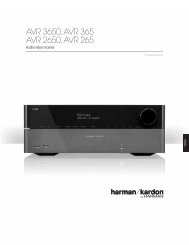
please register your aVr <strong>1600</strong> at<br />
www.harmankardon.com.<br />
note: You’ll need the product’s serial number. At the same<br />
time, you can choose to be notified about new products and/or<br />
special promotions.<br />
thank you for choosing a <strong>Harman</strong> kardon ®<br />
product!<br />
For more than fifty years, the <strong>Harman</strong> <strong>Kardon</strong> ® mission has been to<br />
share a passion for music and entertainment, using leading-edge<br />
technology to achieve premium performance. <strong>Harman</strong> <strong>Kardon</strong>, Inc.,<br />
invented the receiver, a single component designed to simplify<br />
home entertainment without compromising performance. Over<br />
the years, <strong>Harman</strong> <strong>Kardon</strong> products have become easier to use,<br />
while offering more features and sounding better than ever. The<br />
<strong>AVR</strong> <strong>1600</strong> 7.1-channel digital audio/video receiver continues this<br />
tradition with some of the most advanced audio and video processing<br />
capabilities in its class, and a wealth of listening and viewing<br />
options.<br />
To obtain the maximum enjoyment from your new receiver, please<br />
read this manual and refer back to it as you become more familiar<br />
with its features and their operation.<br />
If you have any questions about this product, its installation or its<br />
operation, please contact your <strong>Harman</strong> <strong>Kardon</strong> retailer or custom<br />
installer, or visit the Web site at www.harmankardon.com.<br />
inTRODUCTiOn<br />
<strong>Harman</strong> kardon aVr <strong>1600</strong> 7.1-channel<br />
audio/Video receiver<br />
audio Section<br />
• 50 Watts x 7, two channels driven at full power at 8 ohms,<br />
20Hz – 20kHz,
6<br />
inTRODUCTiOn<br />
audio Inputs<br />
• AM/FM tuner<br />
• CD<br />
• Tape<br />
• Front-panel Analog Audio<br />
• 6-/8-Channel Analog Audio<br />
• Auxiliary mini-jack<br />
audio/Video Inputs<br />
• Three Analog Video<br />
• Front-panel Analog Video<br />
• Two Component Video 100MHz<br />
• Three HDMI (V.1.3a with Deep Color)<br />
• Transcodes component video to HDMI output, preserving<br />
native resolution<br />
• Simultaneous output of component video sources through<br />
component video and HDMI outputs<br />
Digital audio Inputs<br />
• Coaxial: two rear-panel/one front-panel<br />
• Optical: two rear-panel/one front-panel<br />
outputs<br />
• Subwoofer output<br />
• Two Analog Audio<br />
• One Analog Video<br />
• Video Monitor (composite and component)<br />
• Digital Audio (one coaxial)<br />
• HDMI (V.1.3a with Deep Color)<br />
• Headphone<br />
ease of use<br />
• EzSet/EQ automated setup (microphone supplied)<br />
• Text-based on-screen menu system available at composite<br />
video and HDMI outputs (480i only)<br />
• Two-line dot-matrix front-panel display<br />
• Color-coded connections<br />
• Programmable, 11-device remote control<br />
• Source input renaming<br />
• Lip Sync Delay (up to 180msec)<br />
• USB port for system upgrades<br />
Supplied accessories<br />
The following accessory items are supplied with the <strong>AVR</strong> <strong>1600</strong>.<br />
If any of these items are missing, please contact <strong>Harman</strong> <strong>Kardon</strong><br />
customer service at www.harmankardon.com.<br />
• System remote control<br />
• EzSet/EQ microphone<br />
• AM loop antenna<br />
• FM wire antenna<br />
• Three AAA batteries<br />
• Two covers for front-panel jacks
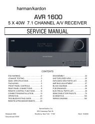
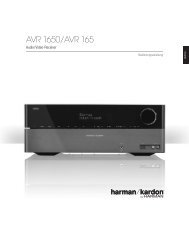
Volume<br />
Source<br />
Selectors<br />
Surround<br />
Select<br />
Message Display<br />
Set<br />
Power<br />
Indicator<br />
FROnT-PAnEL COnTROLS<br />
Headphone<br />
Jack/EzSet/EQ<br />
Video 3<br />
Analog Audio<br />
and Video Inputs<br />
USB Port<br />
Navigation Tuning<br />
/<br />
Microphone<br />
Input<br />
Digital<br />
Input<br />
Channel<br />
Level<br />
Control<br />
Tuning<br />
Mode<br />
Digital Audio<br />
Inputs (Optical 3<br />
and Coaxial 3)<br />
Surround<br />
Mode<br />
Remote<br />
IR Sensor<br />
Standby/On<br />
Switch<br />
note: To make it easier to follow the instructions throughout the manual that refer to this illustration, a copy of this page may be downloaded from the Product<br />
Support section at www.harmankardon.com.<br />
7
8<br />
FROnT-PAnEL COnTROLS<br />
power Indicator: This LED has three possible modes:<br />
• Main Power Off: When the <strong>AVR</strong> is unplugged or the rearpanel<br />
Main Power Switch is off, this LED is off.<br />
• Standby: Amber indicates that the <strong>AVR</strong> is ready to be turned on.<br />
• On: When the <strong>AVR</strong> is turned on, this LED turns white.<br />
note: If the PROTECT message ever appears, turn off the<br />
<strong>AVR</strong> and unplug it. Check all speaker wires for a possible short.<br />
If none is found, bring the unit to an authorized <strong>Harman</strong> <strong>Kardon</strong><br />
service center for inspection and repair before using it again.<br />
Standby/on Switch: This electrical switch turns the<br />
receiver on, or places it in Standby mode for quick turn-on.<br />
tuning mode: This button toggles between manual (one<br />
frequency step at a time) and automatic (seeks frequencies with<br />
acceptable signal strength) tuning mode. It also toggles between<br />
stereo and mono modes when an FM station is tuned.<br />
channel Level control: Press this button to adjust the<br />
output level for any amplifier channel. It may be necessary to raise<br />
or lower the level of a specific channel to compensate for the<br />
placement of the relevant speaker in the room in relation to the<br />
listening position; e.g., the center channel speaker is further away<br />
from the listening position than the front left and right speakers,<br />
so that the dialogue is too soft to hear clearly.<br />
To adjust the level of a channel, press this button once. If the<br />
desired channel is not displayed on screen and in the front-panel<br />
Message Display, use the Tuning Buttons to scroll to it. When<br />
the desired channel appears, use the Navigation Buttons to<br />
change the level.<br />
It is recommended that you avoid changing the channel levels after<br />
you have run the EzSet/EQ setup procedure described in the Initial<br />
Setup section, which properly adjusts all channel levels. See the<br />
Advanced Functions section for more information on manual speaker<br />
setup, including level adjustment.<br />
remote Ir Sensor: This sensor receives infrared (IR)<br />
commands from the remote control. It is important to ensure that it<br />
is not blocked. If covering the sensor is unavoidable, use an optional<br />
<strong>Harman</strong> <strong>Kardon</strong> HE 1000, or other infrared receiver, connecting it to<br />
the Remote IR Input on the <strong>AVR</strong> <strong>1600</strong>’s rear panel.<br />
Digital Input: To change the audio input for the current<br />
source to one of the six digital audio inputs or the analog input for<br />
the source, press this button and use the Navigation Buttons<br />
to change the input. Although any digital audio input may be<br />
assigned to any source, the analog audio inputs are all permanently<br />
dedicated to the source with which they are labeled.<br />
navigation: These buttons are used to navigate the<br />
<strong>AVR</strong>’s menus.<br />
Set: Press this button to select the currently highlighted item.<br />
message Display: Various messages appear in this two-line<br />
display in response to commands and changes in the incoming signal.<br />
In normal operation, the current source name appears on the upper<br />
line, while the surround mode is displayed on the lower line. When<br />
the on-screen display menu system (OSD) is in use, the current<br />
menu settings appear.<br />
tuning: Press these buttons to tune a radio station.<br />
Surround mode: Press this button to select a surround<br />
sound (e.g., multichannel) mode. Each press changes the surround<br />
mode category: AUTO SELECT, VIRTUAL, STEREO, MOVIE, MUSIC,<br />
VIDEO GAME. To change the specific mode within the category, use<br />
the Surround Select Buttons. See the Advanced Functions section<br />
for more information on surround modes.<br />
Surround Select: After you have selected the desired<br />
surround mode category, press these buttons to select a specific<br />
mode within the category, such as to change from Dolby Pro Logic<br />
IIx Movie mode to Logic 7 Movie mode. Surround mode availability<br />
depends on the nature of the source input signal, i.e., digital versus<br />
analog, and the number of channels encoded within the signal.<br />
Source Selectors: Press these buttons to select a source<br />
device, which is a component where a playback signal originates,<br />
e.g., DVD.<br />
Headphone Jack/ezSet/eQ microphone<br />
Input: Plug a 1/4” headphone plug into this jack for private<br />
listening.<br />
This jack is also used to connect the supplied microphone for the<br />
EzSet/EQ procedure described in the Initial Setup section.<br />
Digital audio Inputs (optical 3 and coaxial 3):<br />
Connect a source component that will only be used temporarily,<br />
such as a digital camera or game console, to these jacks. Use only<br />
one type of audio. The audio input may be assigned to any video<br />
source.<br />
uSB port: This port may be used in case a software upgrade<br />
for the receiver is offered in the future. Do not connect a storage<br />
device, peripheral product or a PC here, unless instructed to do<br />
so as part of an upgrade procedure.<br />
Video 3 analog audio and Video Inputs: Connect<br />
a source component that will only be used temporarily, such as a<br />
digital camera or game console, to these jacks. These inputs are<br />
selected as the Video 3 source, and may not be assigned to other<br />
sources.<br />
Volume knob: Turn this knob to raise or lower the volume.
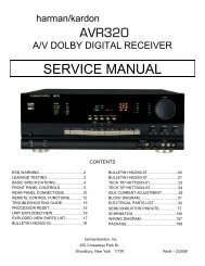
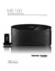
DVD<br />
Audio/Video<br />
Inputs<br />
AC Power Cord<br />
Component<br />
1 & 2<br />
Inputs<br />
HDMI 1-3<br />
Inputs<br />
HDMI Monitor<br />
Output<br />
Video 2<br />
Audio/Video<br />
Inputs<br />
Video 1<br />
Audio/Video<br />
Inputs &<br />
Outputs<br />
Video<br />
Monitor<br />
Output<br />
Component Video<br />
Monitor Output<br />
REAR-PAnEL COnnECTiOnS<br />
FM Antenna<br />
6-/8-Channel<br />
Analog Audio Inputs<br />
Coaxial 1 & 2<br />
Digital Audio Inputs<br />
CD Inputs<br />
AM Antenna<br />
AUX Input<br />
Optical 1& 2<br />
Digital<br />
Audio<br />
Inputs<br />
Main<br />
Power<br />
Switch<br />
Coaxial<br />
Digital<br />
Audio<br />
Output<br />
Center<br />
Speaker<br />
Outputs<br />
Subwoofer<br />
Output<br />
Surround<br />
Speaker<br />
Outputs<br />
Surround<br />
Back<br />
Speaker<br />
Outputs<br />
Front<br />
Speaker<br />
Outputs<br />
Tape Audio<br />
Inputs &<br />
Outputs<br />
note: To make it easier to follow the instructions throughout the manual that refer to this illustration, a copy of this page may be downloaded from the Product<br />
Support section at www.harmankardon.com.<br />
9
10<br />
REAR-PAnEL COnnECTiOnS<br />
am and fm antenna terminals: Connect the included<br />
AM and FM antennas to their respective terminals for radio reception.<br />
component Video monitor output: If you are using<br />
one of the Component Video Inputs and your television or video display<br />
is component-video-capable, connect these jacks to the video display.<br />
note: Due to copy-protection restrictions, there is no output<br />
at the Component Video Monitor Outputs for copy-protected<br />
sources.<br />
component Video 1/2 Inputs: If a video source has<br />
analog component video (Y/Pb/Pr) capability, and if you are not<br />
using an HDMI connection, connect the component video outputs<br />
of the source to one of the sets of component video inputs. Do not<br />
make any other video connections to that source. These inputs may<br />
be assigned to any source.<br />
note: It is not possible to have no component video input<br />
assigned to a source, as the <strong>AVR</strong> <strong>1600</strong> does not transcode<br />
composite video source signals to the component video format.<br />
Thus, if a signal is present at the input assigned to the<br />
source, and you have connected the source device to the<br />
composite video input, you will not see the correct picture<br />
unless you turn off the device connected to the component<br />
video input, or assign the other component video input to the<br />
source.<br />
Video monitor output: If any of your sources use<br />
composite video connections, connect this monitor output to the<br />
corresponding input on your video display. Composite video source<br />
signals are only available at this output.<br />
Video 1, Video 2 and DVD audio/Video<br />
Inputs: These jacks may be used to connect your video-capable<br />
source components (e.g., Blu-ray Disc player, DVD player, cable<br />
TV box) to the receiver.<br />
note: If a source is equipped with an HDMI output, it is<br />
preferable to connect it to one of the <strong>AVR</strong>’s HDMI Inputs. If the<br />
source does not have an HDMI output, use its component or<br />
composite video output, and make a separate audio connection.<br />
Video 1 audio/Video outputs: These jacks may be<br />
used to connect your DVR, VCR or another recorder.<br />
HDmI Inputs and output: HDMI (High-Definition<br />
Multimedia Interface) is a connection for transmitting digital audio<br />
and video signals between devices. Connect up to three HDMIequipped<br />
source devices to the HDMI inputs using a single-cable<br />
connection.<br />
When you connect the HDMI Output to your video display, the<br />
<strong>AVR</strong> <strong>1600</strong> will automatically transcode component video source<br />
signals to the HDMI format, but they will be passed through at<br />
the original resolution and will not be scaled. The <strong>AVR</strong>’s on-screen<br />
menus are visible when the HDMI Output is used, but only at<br />
480i resolution. The main video source will not be visible.<br />
note: When connecting a DVI-equipped display to one of<br />
the HDMI Outputs:<br />
• Use an HDMI-to-DVI adapter.<br />
• Make sure the display is HDCP-compliant. If it isn’t, do not<br />
connect it to an HDMI Output; use an analog video connection<br />
instead.<br />
• Always make a separate audio connection.<br />
ac power cord: After you have made all other connections,<br />
plug the AC power cord into an unswitched wall outlet.<br />
main power Switch: This mechanical switch turns the<br />
power supply on or off. It is usually left on, and cannot be turned<br />
on or off using the remote control.<br />
coaxial 1/2 and optical 1/2 Digital audio<br />
Inputs: If a source has a compatible digital audio output, and<br />
if you are not using an HDMI connection for audio for the device,<br />
connect it to one of these jacks to hear digital audio formats, such<br />
as Dolby Digital, DTS and linear PCM. Use only one type of digital<br />
audio connection for each source.<br />
coaxial Digital audio output: If a source is also<br />
an audio recorder, connect the Coaxial Digital Audio Output to the<br />
recorder’s matching input for improved recording quality. Only PCM<br />
digital audio signals are available for recording. Both coaxial and<br />
optical digital audio signals are available at this Digital Audio Output.<br />
front, center, Surround and Surround Back<br />
Speaker outputs: Use two-conductor speaker wire to<br />
connect each set of terminals to the correct speaker. Remember<br />
to observe the correct polarity (positive and negative connections).<br />
6-/8-channel analog audio Inputs: Connect the<br />
multichannel analog audio outputs of a non-HDMI player (DVD-<br />
Audio, SACD , Blu-ray Disc or HD-DVD, or any other external<br />
decoder) to these jacks. See page 25 for more information.<br />
cD and tape audio Inputs: These jacks may be used<br />
to connect audio-only source components (e.g., CD player, tape<br />
deck). Do not connect a turntable to these jacks unless you are<br />
using it with a phono preamp.<br />
tape outputs: These jacks may be used to connect a CDR<br />
or another audio-only recorder.<br />
Subwoofer output: If you have a powered subwoofer<br />
with a line-level input, connect it to the Subwoofer Output.<br />
auX Input: Enjoy audio from an iPod (not included), CD player<br />
or other portable player by connecting its headphone jack to this<br />
input using a 1/8” stereo mini-plug cable (not included). Video and<br />
still-image playback are not available at this input.
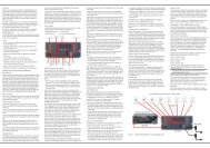
IR Transmitter Lens<br />
Power On<br />
Program Indicator<br />
REMOTE COnTROL FUnCTiOnS<br />
<strong>AVR</strong> Selector<br />
AM/FM<br />
Test Tone<br />
Sleep<br />
Channel Controls<br />
On-Screen Display<br />
Channel Level<br />
Digital Input<br />
Tuning Mode<br />
Direct Station Entry<br />
Tuning<br />
Tone Mode<br />
Night Mode<br />
Track Skip<br />
Transport Controls<br />
6/8CH<br />
Mute<br />
Power Off<br />
Source Selectors<br />
6-/8-Channel Input Selector<br />
Volume Controls<br />
TV/Video<br />
Speaker Setup<br />
OK<br />
Delay<br />
Numeric Keys<br />
Memory<br />
Clear<br />
Preset Stations Selectors<br />
Disc Skip<br />
Macros<br />
Dim<br />
Navigation<br />
note: To make it easier to follow the instructions<br />
throughout the manual that refer to this illustration,<br />
a copy of this page may be downloaded from the<br />
Product Support section at www.harmankardon.com.<br />
11
12<br />
REMOTE COnTROL FUnCTiOnS<br />
The <strong>AVR</strong> <strong>1600</strong> remote is capable of controlling up to 11 devices,<br />
including the <strong>AVR</strong> itself and a device connected to the Auxiliary<br />
Input. During the installation process, you may program the codes<br />
for each of your source components into the remote. Each time you<br />
wish to operate any component or the <strong>AVR</strong>, first press its Selector<br />
Button to change the device mode to the appropriate codes.<br />
Each Input Selector has been preprogrammed to control certain<br />
types of components, with only the codes specific to each<br />
brand and model changing, depending on which product code<br />
is programmed. The device types programmed into each selector,<br />
except the HDMI selectors, may not be changed.<br />
DVD: Controls <strong>Harman</strong> <strong>Kardon</strong> Blu-ray Disc players, and<br />
many brands of DVD players and recorders.<br />
cD: Controls CD players and recorders.<br />
tape: Controls cassette decks.<br />
Video 1: Controls VCRs, TiVo ® devices and DVRs, and<br />
the <strong>Harman</strong> <strong>Kardon</strong> DMC 1000 digital media center.<br />
Video 2: Controls cable and satellite television set-top boxes.<br />
Video 3: Controls televisions and other video displays.<br />
HDmI 1, 2 and 3: Each code set controls a source device<br />
(VCR/PVR, DVD player or cable/satellite set-top box) connected to<br />
one of these inputs.<br />
auX: Controls a device connected to the Auxiliary Input.<br />
Any given button may have different functions, depending on which<br />
component is being controlled. Some buttons are labeled with these<br />
functions. For example, the Sleep Button is labeled for use as the<br />
Channel Up Button when controlling a television or cable box. See<br />
Table A10 in the appendix for listings of the different functions for<br />
each type of component.<br />
Ir transmitter Lens: As buttons are pressed on the<br />
remote, infrared codes are emitted through this lens.<br />
power on Button: Press this button to turn on the <strong>AVR</strong><br />
or another device. The Main Power Switch must first have been<br />
switched on.<br />
mute Button: Press to mute the <strong>AVR</strong> <strong>1600</strong>’s speaker and<br />
headphone outputs. To end the muting, press this button, adjust<br />
the volume or turn off the receiver.<br />
program Indicator: This LED lights up or flashes in one<br />
of three colors as the remote is programmed with codes.<br />
power off Button: Press to turn off the <strong>AVR</strong> <strong>1600</strong> or<br />
another device.<br />
aVr Selector: Press to switch the remote to <strong>AVR</strong> device<br />
mode.<br />
Source Selectors: Press one of these buttons to select<br />
a source device, e.g., DVD, CD, cable TV, satellite or HDTV tuner.<br />
This will also turn on the receiver and switch the remote’s device<br />
mode to operate the source.<br />
am/fm Button: Press this button to select the tuner as the<br />
source, or to switch between the AM and FM bands.<br />
6-/8-channel Input Selector: Press this button to<br />
select the 6-/8-Channel Inputs as the audio source. If a signal is<br />
present at the component video inputs assigned to this source,<br />
it will be used. If not, the receiver will use the video input and<br />
remote control codes for the last-selected analog video source.<br />
test tone: Press this button to activate the test tone for<br />
manual output-level calibration.<br />
tV/Video: This button has no effect on the receiver, but is<br />
used to switch video inputs on some video source components.<br />
Sleep Button: Press this button to activate the sleep timer,<br />
which turns off the receiver after a programmed period of time of<br />
up to 90 minutes.<br />
channel controls: These buttons have no effect on the<br />
receiver, but are used to change channels on TVs and some video<br />
sources.<br />
Volume controls: Press these buttons to raise or lower<br />
the volume, which will be shown in decibels (dB) in the Message<br />
Display.<br />
on-Screen Display (oSD): Press this button to activate<br />
the on-screen menu system.<br />
channel Level: Press this button to adjust the output levels<br />
for any channel so that all speakers sound equally loud at the<br />
listening position.<br />
Speaker Setup: Press this button to configure speaker sizes,<br />
that is, the low-frequency capability of each speaker.<br />
navigation and ok Buttons: These buttons<br />
are used to make selections within the on-screen menu system, or<br />
when accessing the functions of the four buttons surrounding this<br />
area of the remote – Channel Level, Speaker Setup, Digital Input or<br />
Delay.<br />
Digital Input Select: Press this button to select the specific<br />
digital audio input (or analog audio input) to which the current<br />
source is connected.<br />
Delay: Press this button to set delay times that compensate for<br />
placing the speakers at different distances from the listening position,<br />
or to resolve a “lip sync” issue that may be caused by digital<br />
video processing.<br />
note: The Channel Level, Speaker Setup, Digital Input<br />
Select and Delay functions may also be adjusted using the<br />
OSD on-screen menus. In addition, the EzSet/EQ system<br />
may be used to adjust the Channel Level, Speaker Setup<br />
and Delay settings automatically.<br />
numeric keys: Use these buttons to enter radio station<br />
frequencies or to select station presets. Press the Direct Button<br />
before entering the station frequency.
tuning mode: This button toggles between manual (one<br />
frequency step at a time) and automatic (seeks frequencies with<br />
acceptable signal strength) tuning mode. It also toggles between<br />
stereo and mono modes when an FM station is tuned.<br />
memory: After you have tuned a particular radio station, press<br />
this button, then the Numeric Keys, to save that station as a radio<br />
preset.<br />
REMOTE COnTROL FUnCTiOnS<br />
tuning: Press these buttons to tune a radio station. Depending<br />
on whether the tuning mode has been set to manual or automatic,<br />
each press will either change one frequency step at a time, or seek<br />
the next frequency with acceptable signal strength.<br />
Direct: Press this button before using the Numeric Keys to<br />
directly enter a radio station frequency.<br />
clear: Press this button to clear a radio station frequency you<br />
have started to enter.<br />
preset Stations Selector: Press these buttons to select<br />
a preset radio station.<br />
tone mode: Press this button to access the tone controls<br />
(bass and treble). Use the Navigation Buttons to make your<br />
selections.<br />
Disc Skip: This button has no effect on the receiver, but is<br />
used with some optical disc changers to skip to the next disc.<br />
macros: These buttons may be programmed to execute long<br />
command sequences with a single button press. They are useful for<br />
programming the command to turn on or off all of your components,<br />
or for accessing specialized functions for a different component<br />
than you are currently operating.<br />
night mode: Press this button to activate Night mode with<br />
specially encoded Dolby Digital discs or broadcasts. Night mode<br />
compresses the audio so that louder passages are reduced in volume<br />
to avoid disturbing others, while dialogue remains intelligible.<br />
track Skip: These buttons have no effect on the receiver, but<br />
are used with many source components to change tracks or chapters.<br />
Dim: Press this button to partially or fully dim the front-panel display.<br />
transport controls: These buttons have no effect on<br />
the receiver, but are used to control many source components. By<br />
default, when the remote is operating the receiver, these buttons<br />
will control a <strong>Harman</strong> <strong>Kardon</strong> Blu-ray Disc player or a DVD player.<br />
13
14<br />
inTRODUCTiOn TO HOME THEATER<br />
This introductory section will help you to familiarize yourself with<br />
some basic concepts unique to multichannel surround sound<br />
receivers, which will make setup and operation smoother.<br />
typical Home theater System<br />
A home theater typically includes an audio/video receiver, which<br />
controls the system; a disc player; a source component for television<br />
broadcasts (cable box, satellite dish receiver, HDTV tuner or<br />
antenna connected to the TV); a video display (television); and loudspeakers.<br />
multichannel audio<br />
The main benefit of a home theater system is the placement<br />
of loudspeakers around the room to produce “surround sound.”<br />
Surround sound immerses you in the presentation for increased<br />
realism.<br />
The <strong>AVR</strong> <strong>1600</strong> may have up to seven speakers connected directly<br />
to it, plus a subwoofer. Each main speaker is powered by its own<br />
amplifier channel inside the receiver. A system with more than two<br />
speakers is called a multichannel system.<br />
• Front Left and Right – The main speakers are used as<br />
in a 2-channel system. In many surround modes, these speakers<br />
are secondary, while the main action, especially dialogue, is<br />
moved to the center speaker.<br />
• Center – The center speaker is used for dialogue in movies<br />
and television programs, allowing the dialogue to originate near<br />
the actors’ faces, for a more natural sound.<br />
• Surround Left and Right – The surround speakers<br />
improve directionality of ambient sounds. In addition, more loudspeakers<br />
play dynamic soundtracks without risk of overloading<br />
any one speaker.<br />
• Surround Back Left and Right – Additional surround<br />
speakers may be placed behind the listening position, improving the<br />
precision of ambient sounds and allowing for more realistic pans.<br />
The surround back speakers are used with surround modes<br />
designed for 7.1-channel systems, such as Dolby Digital EX,<br />
Dolby Digital Plus, Dolby TrueHD, DTS-ES (Discrete and Matrix),<br />
DTS-HD High Resolution Audio, DTS-HD Master Audio and Logic<br />
7 (7.1 modes). The surround back speakers are optional, and the<br />
<strong>AVR</strong> <strong>1600</strong> may be set up with a 5.1-channel system in the main<br />
listening area.<br />
Many people expect the surround speakers to play as loudly as the<br />
front speakers. Although all of the speakers in the system will be<br />
calibrated to sound equally loud at the listening position, most artists<br />
use the surround speakers for ambient effects only, and they program<br />
their materials to steer very little sound to these speakers.<br />
• Subwoofer – A subwoofer is designed to play only the lowest<br />
frequencies (the bass). It augments smaller, limited-range satellite<br />
speakers used for the other channels. Many digital-format programs,<br />
such as movies recorded in Dolby Digital, contain a low-frequency<br />
effects (LFE) channel which is directed to the subwoofer. The LFE<br />
channel packs the punch of a rumbling train or airplane, or the<br />
power of an explosion, adding realism and excitement to your<br />
home theater. Some people use two subwoofers, for additional<br />
power and even distribution of the sound.<br />
Surround modes<br />
There are different theories as to the best way to present surround<br />
sound and to distribute information to the speakers. A variety of<br />
algorithms have been developed in an effort to reproduce the way we<br />
hear sounds in the real world, resulting in a rich variety of options.<br />
Several companies have taken surround sound in different directions:<br />
• Dolby Laboratories – Dolby TrueHD, Dolby Digital Plus,<br />
Dolby Digital, Dolby Digital EX, Dolby Pro Logic II and IIx<br />
• DTS – DTS-HD High Resolution Audio, DTS-HD Master Audio,<br />
DTS, DTS-ES (Discrete and Matrix), DTS Neo:6, DTS 96/24<br />
• <strong>Harman</strong> International (the <strong>Harman</strong> <strong>Kardon</strong><br />
parent company) – Logic 7, <strong>Harman</strong> Virtual Speaker,<br />
<strong>Harman</strong> Headphone<br />
• Stereo Modes – Generic modes that expand upon conventional<br />
2-channel stereo, including 5- and 7-channel stereo<br />
Table A9 in the appendix contains detailed explanations of the<br />
mode groups and the mode options available within each group.<br />
Digital modes, such as Dolby Digital and DTS, are only available<br />
with specially encoded programs, such as HDTV, Blu-ray Disc<br />
media and digital cable or satellite television. Other modes may be<br />
used with digital and analog signals to create a different surround<br />
presentation, or to use a different number of speakers. Surround<br />
Mode selection depends upon the number of speakers in your<br />
system, the materials you are watching or listening to, and your<br />
personal tastes.
There are different types of audio and video connections used<br />
to connect the receiver, the speakers, the video display, and<br />
the source devices. The Consumer Electronics Association has<br />
established the CEA ® color-coding standard. Some of these<br />
connectors are not used on the <strong>AVR</strong> <strong>1600</strong>, although they may be<br />
found on other components in your system. See Table 1.<br />
Table 1 – Connection Color Guide<br />
Audio Connections<br />
Front (FL/FR)<br />
Center (C)<br />
Surround (SL/SR)<br />
Surround Back (SBL/SBR)<br />
Subwoofer (SUB)<br />
Digital Audio Connections<br />
Coaxial<br />
Optical<br />
Video Connections<br />
Left Right<br />
White Red<br />
Green<br />
Blue Gray<br />
Component Y Green Pb Blue Pr Red<br />
Composite<br />
S-Video<br />
Yellow<br />
HDMI <br />
Connections (digital audio/video)<br />
HDMI<br />
Brown Tan<br />
Purple<br />
Orange<br />
Speaker connections<br />
Speaker cables carry an amplified signal from the receiver’s speaker<br />
terminals to each loudspeaker. They contain two wire conductors,<br />
or leads, inside plastic insulation, that are differentiated in some<br />
way, such as with colors or stripes.<br />
The differentiation preserves polarity, without which low-frequency<br />
performance can suffer. Each speaker is connected to the receiver’s<br />
speaker-output terminals using two wires, one positive (+) and one<br />
negative (–). Always connect the positive terminal on the speaker,<br />
which is usually colored red, to the positive terminal on the<br />
receiver, which is colored as indicated in the Connection Color Guide<br />
(Table 1). The negative terminals are both black.<br />
+<br />
Input<br />
The <strong>AVR</strong> <strong>1600</strong> uses binding-post<br />
speaker terminals that can accept<br />
banana plugs or bare-wire cables.<br />
Banana plugs are inserted into the hole<br />
in the middle of the terminal<br />
cap. See Figure 1.<br />
Figure 1 – Binding-Post Speaker Terminals With Banana Plugs<br />
Bare wire cables are installed as follows (see Figure 2):<br />
1. Unscrew the terminal cap until the pass-through hole is revealed.<br />
2. HOW Insert TO the USE bare THE end BINDING-POST of the wire into the SPEAKER hole. TERMINAL<br />
3. Hand-tighten COMMENT the UTILISER cap LA until BORNE the DES HAUT-PARLEURS wire is held DE CONNEXION snugly.<br />
CÓMO USAR EL TERMINAL DE ALTAVOZ DE POSTE DE SUJECIÓN<br />
1 2 3<br />
Figure 2 – Binding-Post Speaker Terminals With Bare Wires<br />
Always connect colored (+) terminal on <strong>AVR</strong> to red (+) terminal<br />
on speaker; and black (–) to black (–).<br />
Branchez toujours la borne (+) colorée sur <strong>AVR</strong> à la borne (+) rouge sur le haut-parleur;<br />
et la noire (–) à la noire (–).<br />
Conecte siempre el terminal de color (+) en el <strong>AVR</strong> al terminal rojo (+) en el altavoz;<br />
y el negro (–) al negro (–).<br />
Subwoofer<br />
The subwoofer is dedicated to the low frequencies (bass), which<br />
require more power. To obtain the best results, most speaker<br />
manufacturers offer powered subwoofers that contain their own<br />
amplifier. Usually, a line-level (nonamplified) connection is made<br />
from the receiver’s Subwoofer Output to a corresponding jack<br />
on the subwoofer, as shown in Figure 3.<br />
Although the purple subwoofer outputs look similar to full-range<br />
analog audio jacks, they are filtered to allow only the low frequencies<br />
to pass. Don’t connect these outputs to any other devices.<br />
Figure 3 – Subwoofer<br />
COnnECTiOnS<br />
Preout<br />
Subwoofer<br />
connectInG Source DeVIceS<br />
to tHe aVr<br />
Audio and video signals originate in “source devices,” including<br />
your Blu-ray Disc or DVD player, CD player, DVR (digital video<br />
recorder) or other recorder, tape deck, game console, cable or<br />
satellite television box or MP3 player. The <strong>AVR</strong>’s tuner also counts<br />
as a source, even though no external connections are needed,<br />
other than the FM and AM antennas and the SIRIUS tuner module.<br />
Separate connections are required for the audio and video portions<br />
of the signal, except for digital HDMI connections. The types of<br />
connections used depend upon the capabilities of the source device<br />
and video display.<br />
audio connections<br />
There are two types of audio connections: digital and analog.<br />
Digital audio signals are required for listening to sources encoded<br />
with digital surround modes, such as Dolby Digital and DTS, or for<br />
noncompressed PCM digital audio. There are three types of digital<br />
audio connections: HDMI, coaxial and optical. Do not use more<br />
than one type of digital audio connection for each source<br />
device. However, it’s okay to make both analog and digital audio<br />
connections to the same source.<br />
note: HDMI signals may carry both audio and video. If your<br />
video display device has an HDMI input, make a single HDMI<br />
connection from each source device to the <strong>AVR</strong>. Usually, a<br />
separate digital audio connection is not required. Turn the<br />
volume on your television all the way down.<br />
Digital audio<br />
The <strong>AVR</strong> <strong>1600</strong> is equipped with three HDMI (High-Definition<br />
Multimedia Interface) inputs, and one output. HDMI technology<br />
enables digital audio and video information to be carried using<br />
a single cable, delivering the highest quality picture and sound.<br />
The <strong>AVR</strong> <strong>1600</strong> uses HDMI (V.1.3a with Deep Color) technology and<br />
is capable of processing both the audio and video components<br />
of the HDMI data, minimizing the number of cable connections<br />
in your system. The <strong>AVR</strong> <strong>1600</strong> implements Deep Color, which<br />
increases by an order of magnitude the shades of color that can<br />
be displayed, and the latest lossless multichannel audio formats,<br />
including Dolby TrueHD and DTS-HD Master Audio.<br />
15
note: Some DVD-Audio, SACD, Blu-ray Disc and HD-DVD players<br />
only output multichannel audio through their multichannel analog<br />
outputs. Make a separate analog audio connection in addition to the<br />
HDMI connection, which is still used for video and to listen to Dolby<br />
Digital, DTS or PCM materials that may be stored on the disc.<br />
The <strong>AVR</strong> <strong>1600</strong> converts analog video signals to the HDMI format,<br />
including its on-screen menus, but outputs them at their native<br />
resolution.<br />
The HDMI connector is shaped for easy plug-in (see Figure 4). If<br />
your video display has a DVI input and is HDCP-compliant, use an<br />
HDMI-to-DVI adapter (not included). A separate audio connection<br />
is required. HDMI cable runs are limited to about 10 feet.<br />
Figure 4 – HDMI Connection<br />
If your video display or source device is not HDMI-capable, use one<br />
of the analog video connections (composite or component video)<br />
and a separate audio connection.<br />
Coaxial digital audio jacks are usually color-coded in orange.<br />
Although they look similar to analog jacks, you should not connect<br />
coaxial digital audio outputs to analog inputs or vice versa. See<br />
Figure 5.<br />
Coaxial digital<br />
Audio audio Connections<br />
cable<br />
Figure 5 – Coaxial Digital Audio<br />
Left Right<br />
Front Optical (FL/FR) digital audio connectors are normally covered by a shutter<br />
Center to protect (C) them from dust. The shutter opens as the cable is inserted.<br />
Surround Input connectors (SL/SR) are color-coded using a black shutter, while outputs<br />
Subwoofer use a gray (SUB) shutter. See Figure 6.<br />
Optical<br />
Optical digital<br />
Digital Audio Connections<br />
audio cable<br />
Coaxial Figure 6 – Optical Digital Audio<br />
Optical analog audio<br />
Output Input<br />
Video Analog Connections connections require two cables, one for the left channel<br />
(white) and one for the right channel (red). These two cables are<br />
Component Y Pb Pr<br />
often attached to each other. See Figure 7.<br />
Composite<br />
For sources that are capable of both digital and analog audio, you<br />
S-Video<br />
may make both connections.<br />
You may only record materials from DVDs or other copy-protected<br />
sources using analog connections. Remember to comply with all<br />
copyright laws, if you choose to make a copy for your own<br />
personal use.<br />
Analog audio<br />
cable (RCA)<br />
Figure 7 – Analog Audio<br />
16<br />
COnnECTiOnS<br />
Coaxial<br />
The 6-/8-Channel Inputs are multichannel analog connections<br />
that are used with high-definition sources that decode the copyprotected<br />
digital content, such as some DVD-Audio, SACD, Blu-ray<br />
Disc and HD-DVD players. See Figure 8. The multichannel analog<br />
audio connection is not required for players compliant with HDMI<br />
version 1.1 or better, or that output linear PCM signals via an HDMI<br />
connection.<br />
L<br />
R<br />
Consult the owner’s guide for your disc player for more information,<br />
and see page 25.<br />
Multichannel<br />
analog audio<br />
cable (RCA)<br />
Figure 8 – Multichannel Analog Audio<br />
Front Surround Center<br />
White<br />
Blue Green<br />
Subwoofer<br />
Red Gray Purple<br />
The <strong>AVR</strong> <strong>1600</strong> has an Auxiliary Audio Input on the rear panel in the<br />
form of a stereo 1/8” mini jack. Connect the headphone output of<br />
any audio source, such as an MP3 player or portable CD player, to<br />
the Auxiliary Audio Input. See Figure 9.<br />
Figure 9 – Auxiliary Audio Input<br />
Video connections<br />
Many sources output both audio and video signals (e.g., Blu-ray<br />
Disc or DVD player, cable television box, HDTV tuner, satellite box,<br />
VCR, DVR). In addition to the audio connection, make one type of<br />
video connection for each of these sources (only one at a time for<br />
any source).<br />
Digital Video<br />
If you have already connected a source device to one of the HDMI<br />
inputs, you have automatically made a video connection, as the<br />
HDMI signal includes both digital audio and video components.<br />
analog Video<br />
There are two types of analog video connections used on the<br />
<strong>AVR</strong> <strong>1600</strong>: composite video and component video.<br />
Composite video is the basic connection most commonly available.<br />
The jack is usually color-coded yellow, and looks like an analog<br />
audio jack. Do not plug a composite video cable into an analog<br />
or coaxial digital audio jack, or vice versa. Both the chrominance<br />
(color) and luminance (intensity) components of the video signal<br />
are transmitted using a single cable. See Figure 10.<br />
Composite<br />
video cable<br />
Figure 10 – Composite Video<br />
Component video separates the video signal into three<br />
components – one luminance (“Y”) and two sub-sampled color<br />
signals (“Pb” and “Pr”) – that are transmitted using three separate<br />
cables. See Figure 11.<br />
Y Green<br />
Component<br />
video cable<br />
Pb Blue<br />
Pr Red<br />
Figure 11 – Component Video
If it’s available on your video display, an HDMI connection is<br />
recommended as the best quality connection, followed by<br />
component video, and then composite video.<br />
note: HDCP-copy-protected sources are not available at<br />
the Component Video Monitor Outputs.<br />
antennaS<br />
The <strong>AVR</strong> <strong>1600</strong> uses separate terminals for the included FM and AM<br />
antennas.<br />
The FM antenna uses a 75-ohm F-connector. See Figure 12.<br />
Figure 12 – FM Antenna<br />
The AM loop antenna needs to be assembled. Connect the two<br />
leads to the spring terminals on the receiver. The AM antenna leads<br />
have no polarity, and you may connect them to either terminal.<br />
See Figure 13.<br />
Figure 13 – AM Antenna<br />
uSB port<br />
The USB Port on the <strong>AVR</strong> <strong>1600</strong> is used only for software upgrades.<br />
If an upgrade for the receiver’s operating system is released in the<br />
future, it may be downloaded to the <strong>AVR</strong> using this port. Complete<br />
instructions will be provided at that time.<br />
COnnECTiOnS<br />
17
Optimally, the speakers should be placed in a circle with the listening<br />
position at its center. The speakers should be angled so that they<br />
directly face the listening position.<br />
front Speaker placement<br />
The center speaker is placed either on top of, below or mounted on<br />
the wall above or below the video display SUB screen.<br />
C<br />
The front left and right FL speakers are FR placed along the circle, about<br />
30° 30°<br />
30 degrees from the center speaker and angled toward the listener.<br />
Place the front left/right 90° and center 90° speakers at the same height,<br />
SL SR<br />
150°<br />
preferably at about the same height 150° as the listener’s ears. The<br />
center speaker should be no more than 2 feet above or below<br />
the left/right speakers. If you’re using only two speakers with<br />
the <strong>AVR</strong> <strong>1600</strong>, place them in the front left and right positions.<br />
SBL<br />
SBR<br />
Placement of the surround speakers depends on the number of<br />
speakers in your system.<br />
18<br />
SPEAKER PLACEMEnT<br />
White<br />
FL<br />
110°<br />
150°<br />
Alternate placement<br />
for Side Surround<br />
Left Speaker (Blue)<br />
Green<br />
C<br />
30° 30°<br />
SUB Purple<br />
FR<br />
110°<br />
150°<br />
Blue SL SR Gray<br />
Figure 14 – Speaker Placement (5.1-Channel System)<br />
Red<br />
Alternate placement<br />
for Side Surround<br />
Right Speaker (Gray)<br />
placement of Surround Speakers in a<br />
5.1-channel System<br />
The side surround speakers should be placed 110 degrees from<br />
the center speaker, slightly behind and angled toward the listener.<br />
Alternatively, place them behind the listener, with each surround<br />
speaker facing the opposite-side front speaker. See Figure 14.<br />
The surround speakers may be placed a little higher than the<br />
listener’s ears.<br />
placement of Surround Speakers in a<br />
7.1-channel System<br />
In a 7.1-channel system, the side surround speakers are placed<br />
90 degrees from the center speaker, directly to either side of the<br />
listening position. The surround back left and right speakers are<br />
placed 150 degrees from the center speaker, or directly facing the<br />
opposite-side front speaker. See Figure 15.<br />
Blue SL<br />
White<br />
Brown<br />
SPEAKER PLACEMENT<br />
PLACEMENT DES HAUT-PARLEURS. COLOCACIÓN DE LOS ALTAVOCES<br />
FL<br />
90°<br />
150°<br />
SBL<br />
FL<br />
Green<br />
Figure 15 – Speaker Placement (7.1-Channel System)<br />
30° 30°<br />
C<br />
SUB<br />
note: Some speaker manufacturers offer 6.1-channel<br />
speaker systems, for 6.1-channel surround sound formats,<br />
such as Dolby Digital EX, DTS-ES Discrete and Matrix modes<br />
and DTS Neo:6 mode. Using the <strong>AVR</strong> <strong>1600</strong> in a 6.1-channel<br />
configuration is not recommended. 110° The 6.1-channel formats 110°<br />
will sound better SL when played 150° through a 7.1-channel sys- 150°<br />
tem. The same surround back channel information is played<br />
through both surround back speakers, but with twice the<br />
power and clarity.<br />
To use the <strong>AVR</strong> <strong>1600</strong> with a 6.1-channel speaker system,<br />
place the single surround back speaker directly behind<br />
the listener, but do not connect it until after you have run<br />
the EzSet/EQ procedure for a 5.1-channel system. After<br />
the EzSet/EQ process finishes, connect the surround back<br />
speaker to the Surround Back Left Speaker Output. Then<br />
follow the directions in SBL the Advanced Functions section for SBR<br />
manual setup of the surround back speaker.<br />
Subwoofer placement<br />
Placement of the subwoofer is less critical, since low-frequency<br />
sounds are omnidirectional. Placing the subwoofer close to a wall<br />
or in a corner will reinforce the low frequencies, and may create<br />
a “boomy” sound. Temporarily place the subwoofer where the<br />
listener normally sits, then walk around the room until the low<br />
frequencies sound best. Place the subwoofer in that spot.<br />
note: Your receiver will sound its best when the same<br />
model or brand loudspeaker is used for all positions.<br />
C<br />
30° 30°<br />
SUB<br />
FR<br />
90°<br />
150°<br />
Purple<br />
Red<br />
SBR Tan<br />
SR Gray<br />
FR
Installing the <strong>AVR</strong> <strong>1600</strong> and connecting it to the other system components<br />
can be complicated. To simplify installation, it is suggested that you<br />
design your system before you begin connecting wires and cables.<br />
Although the rear-panel jacks allow for a variety of audio and video<br />
connections to other components, the <strong>AVR</strong> organizes the connections<br />
into six conventional sources: DVD (Blu-ray Disc player or DVD<br />
player), CD, Tape (audio recorder), Video 1 (VCR), Video 2 (Cable/<br />
Sat) and Video 3 (TV). Each of these sources uses dedicated analog<br />
audio inputs, and the DVD and Video 1/2/3 sources also use dedicated<br />
composite video inputs.<br />
The <strong>AVR</strong> <strong>1600</strong> also features six digital audio inputs (two each coaxial<br />
and optical on the rear panel, and one of each type on the front<br />
panel). The digital audio inputs, which offer improved performance<br />
when available on the source device, may be assigned to any<br />
source, as explained in the Initial Setup section.<br />
The two component video inputs offer improved video performance<br />
when available on the source device and video display, and may<br />
also be assigned to any source.<br />
The 6-/8-Channel Analog Audio Inputs are selected as a separate<br />
source, but may only be used with one of the two component video<br />
inputs.<br />
For superior audio and video performance, the <strong>AVR</strong> <strong>1600</strong> is<br />
equipped with three dedicated HDMI inputs, which may be used<br />
with any type of source device that has an HDMI output. The HDMI<br />
inputs may be used with an analog or digital audio input or one of<br />
the component video inputs. This flexibility facilitates using the <strong>AVR</strong><br />
with sources that do not output multichannel audio through their<br />
HDMI outputs.<br />
Table A1 in the appendix indicates the default audio/video connection<br />
assignments. If the defaults suit your system, then connect<br />
your devices to the audio/video inputs shown. Otherwise, design<br />
your system as explained below.<br />
1. Best video connection type for your system:<br />
Examine the video inputs on your TV or video display. Write down<br />
the best available video connection type here: ____________.<br />
GETTinG STARTED<br />
The options, in order of preference, are: HDMI, DVI (must be HDCPcompliant),<br />
component video or composite video. This is the<br />
“system-best” video connection for your system.<br />
2. Decide which source will be used for each<br />
device: Match up to six devices to the six conventional sources<br />
listed in the Table 2 worksheet below. Any source device with<br />
compatible output connectors may be connected to any source<br />
inputs on the <strong>AVR</strong>. Matching the source devices to the named<br />
sources simplifies setup and programming the remote control.<br />
It is recommended that you match source devices as follows:<br />
• DVD: Blu-ray Disc player or DVD player (remote may only<br />
operate <strong>Harman</strong> <strong>Kardon</strong> Blu-ray Disc players, or many brands<br />
of DVD players)<br />
• VIDEO 1: VCR, PVR (such as TiVo), DVD recorder<br />
• VIDEO 2: Cable or satellite set-top box<br />
• VIDEO 3: TV (video display) or HDTV set-top box<br />
• CD: CD player<br />
• TAPE: Cassette deck or audio recorder (remote may only<br />
operate <strong>Harman</strong> <strong>Kardon</strong> cassette decks)<br />
• HDMI 1, 2 or 3: Any device equipped with an HDMI output;<br />
the device type is selected from one of the other options while<br />
programming the remote<br />
• AUX: Portable audio player (remote is not programmable to<br />
operate this device)<br />
3. Best video connection for each source: Examine<br />
each source device and write down the best available type of video<br />
connection, but not better than the system-best connection. Leave<br />
blank audio-only sources, such as a CD player.<br />
4. Best audio connection for each source: For each<br />
source device, write down the best available type of audio connection.<br />
See the note below, and if the HDMI connection may be used for<br />
audio, it is the best option. The other options, in order of preference,<br />
are: optical digital audio, coaxial digital audio, 2-channel analog audio.<br />
Table 2 – Source Assignment Worksheet<br />
Source Device Type Best Video Video Input Best Audio Audio Input Analog Audio<br />
Connection Assigned Connection Assigned (may Input for<br />
(HDMI, DVI, (HDMI, Optical, be one digital Recording<br />
Component, Coaxial, 2-CH plus one or more<br />
Composite) Analog analog)<br />
Video 1 VCR<br />
Video 2 Cable or Sat<br />
Video 3 TV<br />
DVD Blu-ray Disc or DVD<br />
CD CD<br />
Tape Cassette deck<br />
AUX<br />
HDMI 1<br />
HDMI 2<br />
HDMI 3<br />
Portable player<br />
6-/8-CH 6-/8-CH 6-/8-CH<br />
19
20<br />
GETTinG STARTED<br />
If you select an HDMI input, that becomes the <strong>AVR</strong> source for the<br />
device. If you select a 2-channel analog audio input, that input<br />
becomes the <strong>AVR</strong> source. The digital audio inputs will be assigned<br />
to a source during Initial Setup.<br />
noteS:<br />
• For multichannel disc players, if both the device and the<br />
TV use HDMI connections for video, then check the owner’s<br />
manual for the device to determine whether it transmits<br />
multichannel audio via its HDMI output. If it does, then no<br />
separate audio connection is required. If not, write down<br />
the multichannel analog audio connection in addition to any<br />
other audio type. An analog video connection, in addition<br />
to the HDMI connection, will be required. See page 25 for<br />
more information.<br />
• If the device uses an HDCP-compliant DVI output for video,<br />
then connect it to one of the <strong>AVR</strong>’s HDMI Inputs using an<br />
HDMI-to-DVI adapter, but a separate audio connection will<br />
always be required.<br />
• The AUX Input jack on the rear panel requires a 1/8” stereo<br />
audio mini-plug. Purchase a stereo audio cable with 1/8”<br />
mini-plugs at both ends. Connect one end to the 1/8” headphone<br />
jack found on may portable audio players, and plug<br />
the other end of the cable into the AUX Input jack. The AUX<br />
Input may also be used with audio devices that have conventional<br />
left and right analog audio output jacks. Purchase<br />
a cable that has left and right “RCA-style” plugs at one end<br />
and a 1/8” mini-plug at the other end to connect the player<br />
to the AUX Input.<br />
5. Decide which sources to connect to each of<br />
the video inputs: Assign only one unique video input to<br />
each source. Use the best type of video connection available for<br />
each source.<br />
• If your system-best video connection is “HDMI”, select up to<br />
three HDMI source devices and assign them to one of the<br />
HDMI sources.<br />
• If your system-best video connection is “Component”, or if you<br />
have source devices with component video outputs that weren’t<br />
assigned to one of the HDMI Inputs, assign up to two devices<br />
to one of the numbered Component Video Inputs.<br />
• If your system-best video connection is “Composite Video”, or if<br />
you have source devices with composite video outputs that have<br />
not been assigned to any other video input, then assign the devices<br />
to one of the four conventional sources (DVD, Video 1, 2 or 3).<br />
The composite video inputs are dedicated to each source and<br />
may not be reassigned. Use the composite video input for the<br />
source you assigned to the device in number 2 above.<br />
note: If the source device is a video recorder that will<br />
be used to record from other devices connected to the<br />
<strong>AVR</strong>, assign the recorder to the Video 1 Input, which has a<br />
recording output. Any of the Coaxial or Optical Digital Inputs<br />
may be assigned to the recorder for audio, if it is capable<br />
of making digital audio recordings. To make audio-only<br />
recordings, assign the Tape source to the recorder. It is not<br />
necessary to connect TiVo or PVR devices that will only record<br />
from their direct cable or satellite television signals to the<br />
<strong>AVR</strong>’s recording outputs.<br />
6. Decide which audio inputs to connect to each<br />
source: Assign only one unique digital audio input to each<br />
digital source. Analog audio inputs are used for analog sources,<br />
or as secondary connections for digital sources for backup or for<br />
recording. The 2-channel analog audio inputs are dedicated to the<br />
four conventional sources (DVD, Video 1, 2 or 3) and may not be<br />
reassigned. Use the 2-channel analog audio input for the source<br />
you assigned to the device in number 2 above.<br />
• Any source using an HDMI Input requires no additional connection<br />
for audio unless:<br />
u The source doesn’t output multichannel audio through its HDMI<br />
output. Make a second connection to the 6-/8-Channel Analog<br />
Audio Inputs.<br />
u The source has an HDCP-compliant DVI output for video only.<br />
Assign a digital or analog audio input.<br />
• For any source whose best audio connection is optical or coaxial<br />
digital audio, assign one of the three Optical or three Coaxial<br />
Digital Audio Inputs. Do not connect both types of digital audio<br />
to the same source device.<br />
• You may use one of the 2-Channel Analog Audio Inputs for<br />
a digital source.<br />
• You may also assign the 6-/8-Channel Analog Audio Inputs,<br />
if available, to a digital source. See page 25.<br />
• Use the 2-channel Analog Audio Input for the source selected<br />
for the device in number 2 above when the device is an analog<br />
source.<br />
note: If the source device is a digital audio recorder, it<br />
may be used with any of the Coaxial or Optical Digital Audio<br />
Inputs and the Coaxial Digital Audio Output. Both coaxial<br />
and optical signals are available at the Coaxial Digital Audio<br />
Output. To make analog recordings, assign either the Analog<br />
2 or 4 Audio Inputs to the recorder, as both have recording<br />
outputs.
You are now ready to begin installing the <strong>AVR</strong>. Before beginning to<br />
connect the various components to the receiver, turn off all devices,<br />
including the <strong>AVR</strong> <strong>1600</strong>, and unplug their power cords. Don’t plug<br />
in any of the power cords until you have finished making all of<br />
your connections.<br />
The receiver generates heat. Select a location that leaves several<br />
inches of space on all sides. Avoid completely enclosing the receiver<br />
inside an unventilated cabinet. Place components on separate<br />
shelves rather than stacking them directly on top of the receiver.<br />
Never block the <strong>AVR</strong>’s ventilation slots on the top and side panels.<br />
Doing so could cause the <strong>AVR</strong> to overheat, with potentially serious<br />
consequences. Some shelf surface finishes are delicate. Try to<br />
select a location with a sturdy surface finish.<br />
tIp: Label each cable before connecting it, to avoid mistakes.<br />
Write a description of the cable on a blank adhesive<br />
label, e.g., “DVD”, and fold the label around the cable about 6<br />
inches from the end to be plugged into the <strong>AVR</strong>.<br />
Almost all of the following installation steps are optional, depending<br />
on your system. Skip any step that does not apply to your system.<br />
Step one – Connect Source Devices<br />
Leaving all AC power cords unplugged, connect the source devices<br />
to the <strong>AVR</strong> using the audio and video inputs you assigned in Table 2.<br />
Step tWo – Connect TV<br />
Connect the system-best video input on the TV to the corresponding<br />
video monitor output on the <strong>AVR</strong>.<br />
Step tHree – Connect Loudspeakers<br />
After you have placed your loudspeakers in the room as explained<br />
on page 18, connect each speaker to its color-coded terminal on the<br />
<strong>AVR</strong>. Maintain proper polarity by connecting the negative terminal on<br />
the speaker (usually colored black) to the negative terminal on the<br />
<strong>AVR</strong> (also colored black); and the positive terminal on the speaker<br />
(usually red) to the positive terminal on the <strong>AVR</strong> (color varies by<br />
channel; see Table 1 on page 15).<br />
If you have a subwoofer, connect its line-level or LFE input to the<br />
purple Subwoofer Output.<br />
note: If the subwoofer only has speaker-level inputs, after<br />
you have configured the <strong>AVR</strong> using EzSet/EQ technology as<br />
described on page 23, connect the subwoofer’s left and right<br />
speaker input terminals to the <strong>AVR</strong>’s Front Left and Front Right<br />
Speaker Outputs, then connect the front left and right main<br />
speakers to the subwoofer’s left and right speaker output<br />
terminals. Consult the owner’s manual for the subwoofer for<br />
specific installation instructions.<br />
Step four – Connect FM Antenna<br />
Connect the included FM antenna to the 75-ohm FM antenna terminal.<br />
Step fIVe – Connect AM Antenna<br />
Assemble the included AM antenna (see Figure 16) and connect it<br />
to the AM and Ground antenna terminals. The antenna is not polarized,<br />
and either lead may be connected to either terminal.<br />
Figure 16 – AM Antenna Assembly<br />
inSTALLATiOn<br />
Step SIX – Plug in AC Power Cords<br />
Before plugging the <strong>AVR</strong> into an unswitched electrical outlet, make<br />
sure the Main Power Switch on the rear panel is off, to prevent the<br />
possibility of damaging the <strong>AVR</strong> in case of a transient power surge.<br />
Plug the AC Power cord into an unswitched AC outlet.<br />
It is recommended that you copy the appropriate information from<br />
the Table 2 worksheet to Table A5 in the appendix for future reference,<br />
in the event changes are made to the system components.<br />
Step SeVen – Insert Batteries in Remote<br />
The <strong>AVR</strong> <strong>1600</strong> remote control uses three AAA batteries (included).<br />
To remove the battery cover located on the back of the remote,<br />
firmly press the ridged depression and slide the cover toward the<br />
top of the remote.<br />
Insert the batteries as shown in Figure 17, observing the correct<br />
polarity.<br />
Figure 17 – Remote Battery Compartment<br />
Point the remote’s lens toward the front panel of the <strong>AVR</strong> <strong>1600</strong>.<br />
Make sure no objects, such as furniture, are blocking the remote’s<br />
path to the receiver. Bright lights, fluorescent lights and plasma<br />
video displays may interfere with the remote’s functioning. The<br />
remote has a range of about 20 feet, depending on the lighting<br />
conditions. It may be used at an angle of up to 30 degrees to either<br />
side of the <strong>AVR</strong>.<br />
If the remote control seems to operate intermittently, or if pressing<br />
a button on the remote does not cause one of the Source Selectors<br />
to light, check or replace the batteries.<br />
Step eIGHt – Program Sources Into the<br />
remote<br />
The <strong>AVR</strong> <strong>1600</strong> remote may be programmed to control many brands<br />
and models of DVD players, cable boxes, satellite receivers, the<br />
<strong>Harman</strong> <strong>Kardon</strong> DMC 1000 digital media center and TVs.<br />
To access the functions for a particular device, switch the remote’s<br />
device mode. Press the <strong>AVR</strong> Button to access the codes that control<br />
the receiver, or the Source Selector Buttons to access the codes for<br />
the devices programmed into the remote.<br />
21
22<br />
inSTALLATiOn<br />
While the DVD Source Selector may be used to operate either a<br />
<strong>Harman</strong> <strong>Kardon</strong> Blu-ray Disc player or a DVD player, the default<br />
mode is to operate a <strong>Harman</strong> <strong>Kardon</strong> Blu-ray Disc player. To toggle<br />
between <strong>Harman</strong> <strong>Kardon</strong> Blu-ray Disc player and DVD player operation,<br />
press and hold the DVD Source Selector for 2 seconds. The<br />
source selector will flash twice to confirm that the remote’s mode<br />
has changed to operate the other type of disc player.<br />
note: The remote may be easily programmed to operate<br />
the DMC 1000 digital media center, using the Video 1 or<br />
any of the HDMI Input Selectors, by following the instructions<br />
below. Select the VCR/PVR/DMC device type in number 4.<br />
Enter code 003.<br />
If you have other source devices in your system, follow these steps<br />
to program the correct codes into the remote.<br />
1. Using the codes in Tables A11– A17 of the Appendix, look up the<br />
product type (e.g., DVD, cable TV box) and the brand name of<br />
your source. The number(s) listed is/are potential candidates for<br />
the correct code set for your particular device.<br />
2. Turn on your source device.<br />
3. This step places the remote in program mode. Press and hold<br />
the Source Selector until the Program Indicator LED on the<br />
remote starts to flash, then release it. When pressed, the Source<br />
Selector will light red briefly, go dark, and then relight when the<br />
Program Indicator LED starts to flash.<br />
4. Program the desired device type for any of the three HDMI<br />
selectors by pressing the corresponding Source Selector:<br />
• Press DVD to operate a DVD player.<br />
• Press VID1 to operate a VCR or PVR, or a <strong>Harman</strong> <strong>Kardon</strong><br />
digital media center.<br />
• Press VID2 to operate a cable or satellite set-top box.<br />
5. Enter a code from number 1 above.<br />
a) If the device turns off, then press the Source Selector again to<br />
accept the code; it will flash. The remote will exit the Program<br />
mode.<br />
b) If the device does not turn off, try entering another code. If you<br />
run out of codes, you may search through all of the codes in the<br />
remote’s library for that product type by pressing the 1 or 5<br />
Button repeatedly until the device turns off. When the device<br />
turns off, enter the code by pressing the Source Selector; it will<br />
flash. The remote then exits Program mode.<br />
6. Once you have programmed a code, try using some other functions<br />
to control the device. Sometimes manufacturers use the<br />
same Power code for several different models, while other codes<br />
vary. Repeat this process until you’ve programmed a satisfactory<br />
code set that operates most of the functions you frequently use.<br />
7. Find out which code number you have programmed by pressing<br />
and holding the Source Selector to enter the Program mode.<br />
Press the OK Button, and the Program Indicator LED will flash<br />
in the code sequence. One flash represents “1”, two flashes for<br />
“2”, and so forth. A series of many fast flashes represents “0”.<br />
Record the codes programmed for each device in Table A7 in the<br />
Appendix.<br />
If you are unable to locate a code set that correctly operates your<br />
source device, it will not be possible to use the <strong>AVR</strong> remote to control<br />
that device. You may still connect the source to the <strong>AVR</strong> <strong>1600</strong> and<br />
operate it using the device’s original remote control.<br />
Most of the button labels on the remote describe the button’s function<br />
when used to control the <strong>AVR</strong> <strong>1600</strong>. However, the button may perform<br />
a very different function when used to control another device. Refer<br />
to the Remote Control Function List, Table A10 in the Appendix, for<br />
each button’s functions with the various product types.<br />
You may program Macros, which are preprogrammed code<br />
sequences that execute many code commands with a single button<br />
press. You may also program “punch-through” codes, which allow<br />
the remote to operate the volume, channel or transport controls<br />
of another device without having to switch the remote’s device<br />
mode. See pages 35 through 36 for instructions on these advanced<br />
programming functions.<br />
note: The <strong>AVR</strong> <strong>1600</strong> remote is preprogrammed to operate<br />
the transport controls of <strong>Harman</strong> <strong>Kardon</strong> Blu-ray Disc or DVD<br />
players when the <strong>AVR</strong> or the Video 2 (cable/satellite) or Video<br />
3 (TV) source is selected. You may change this punch-through<br />
programming at any time.<br />
Step nIne – Turn On the <strong>AVR</strong> <strong>1600</strong><br />
Two steps are required the first time you turn on the <strong>AVR</strong> <strong>1600</strong>.<br />
1. Flip the rear-panel Main Power Switch to the “On” position. The<br />
Power Indicator on the front panel will turn amber, indicating<br />
that the <strong>AVR</strong> is in Standby mode and is ready to be turned on.<br />
Normally, you may leave the Main Power Switch on, even when<br />
the receiver is not being used.<br />
2. There are several ways to turn on the <strong>AVR</strong> from Standby mode.<br />
a) Press the Standby/On Switch on the front panel.<br />
b) Using the remote, press the Power On Button or any of the<br />
Source Selectors.<br />
noteS:<br />
• Any time you press one of the Source Selectors on the<br />
remote, the remote will switch device modes. To control the<br />
receiver, press the <strong>AVR</strong> Button.<br />
• If you do not see a picture within about one minute, refer<br />
to the Video Troubleshooting Tips on page 28.
In this section, you will configure the <strong>AVR</strong> <strong>1600</strong> to match your actual<br />
system. A video display must be connected to one of the video<br />
monitor outputs on the receiver.<br />
uSInG tHe on-Screen menu SyStem<br />
Although it’s possible to configure the <strong>AVR</strong> using only the remote<br />
and the front-panel messages, it is easier to use the full-screen<br />
menu system.<br />
The menu system is accessed by pressing the OSD Button on the<br />
remote.<br />
The Master menu will appear (see Figure 18).<br />
Figure 18 – Master Menu<br />
The Master menu consists of five submenus: Input Setup, Surround<br />
Select, EzSet/EQ, <strong>Manual</strong> Setup and System Setup.<br />
Use the Buttons on the remote to navigate the menu<br />
system, and press the OK Button to select a menu or setting line,<br />
or to enter a new setting.<br />
The current menu, setting line or setting will appear in the Message<br />
Display, as well as on screen.<br />
To return to the previous menu, navigate to the “BACK TO MASTER<br />
MENU” line and press the OK Button. To exit the menu system,<br />
press the OSD Button.<br />
Most users should follow the instructions in this Initial Setup section<br />
to configure a basic home theater system. You may return to these<br />
menus at any time to make additional adjustments, such as those<br />
described in the Advanced Functions section.<br />
Before beginning initial setup, all loudspeakers, a video display and<br />
all source devices should be connected. You should be able to turn<br />
on the receiver and view the Master menu when you press the OSD<br />
Button. If necessary, reread the Installation Section and the beginning<br />
of this section before continuing.<br />
configure the aVr <strong>1600</strong>, using ezSet/eQ<br />
technology<br />
One of the most important steps in setting up a home theater<br />
system is to calibrate the receiver to match the loudspeakers,<br />
optimizing sound reproduction.<br />
Until recently, most receivers required manual calibration and<br />
configuration, a tedious process that called for a good ear or the<br />
purchase of an SPL (sound-pressure level) meter. Although you may<br />
configure the <strong>AVR</strong> <strong>1600</strong> manually, as described in the Advanced<br />
Functions section, it is recommended that you take advantage of<br />
the signature <strong>Harman</strong> <strong>Kardon</strong> EzSet/EQ system.<br />
iniTiAL SETUP<br />
Eliminate extraneous background noise, such as noisy air conditioning.<br />
Avoid making any loud noises while running EzSet/EQ setup.<br />
Important Safety note: During the EzSet/EQ<br />
procedure, a series of very loud test sweeps will be played<br />
through all of the speakers. Avoid sitting or standing close to<br />
any one speaker during the procedure. If you are particularly<br />
sensitive to loud noises, you may wish to leave the room and<br />
have someone else run the EzSet/EQ process.<br />
STEP OnE – Place the included EzSet/EQ microphone in the<br />
listening position or in the center of the room, at about the same<br />
height as the listeners’ ears. The microphone features a threaded<br />
insert on the bottom, for mounting on a camera tripod.<br />
STEP TWO – Plug the EzSet/EQ microphone into the<br />
Headphone Jack/EzSet/EQ Microphone Input Jack on the front of<br />
the receiver, and set the level control on the subwoofer to the halfway<br />
point.<br />
Step tHree – Turn on the <strong>AVR</strong> <strong>1600</strong> and the video display.<br />
Press the OSD Button to display the Master menu. Use the Button<br />
to highlight the EzSET/EQ LINE, then press the OK Button. See Figure 19.<br />
Figure 19 – EzSet/EQ Screen<br />
Select “YES”, and a warning screen, followed by the screen shown<br />
in Figure 20, will appear.<br />
Figure 20 – EzSet/EQ Screen<br />
To return to the SPEAKER SETUP menu without starting the<br />
EzSet/EQ process, select “Cancel”. When you are ready to begin,<br />
select the number of speakers in your system. Select 5.1 if no<br />
surround back speakers are present.<br />
23
24<br />
iniTiAL SETUP<br />
note: If there are fewer than five main speakers in your<br />
system, do not use the EzSet/EQ process. Instead, proceed<br />
as described in the Advanced Functions section. If you have<br />
selected a 6.1-channel configuration with a single surround<br />
back speaker, use EzSet/EQ automatic configuration for<br />
5.1 speakers, connect the single surround back speaker<br />
to the left Surround Back Speaker Output, then configure<br />
the surround back speaker manually, as described in the<br />
Advanced Functions section. The 6.1-channel configuration<br />
is not recommended. If the subwoofer is to be connected to<br />
the Front Speaker Outputs, do not connect the subwoofer until<br />
after running the EzSet/EQ process.<br />
The <strong>AVR</strong> <strong>1600</strong> will automatically set its master volume to – 25dB.<br />
The test will begin, and a screen such as the one shown in Figure 21<br />
will appear. Maintain silence during the EzSet/EQ configuration.<br />
Figure 21 – EzSet/EQ in Progress<br />
As the EzSet/EQ system tests each speaker, its position will appear<br />
on screen. If the test sweep is heard from a different speaker than<br />
the one indicated on screen, turn off the <strong>AVR</strong> and check the speaker-wire<br />
connections, then begin again.<br />
When the test is completed, select the Continue option. The results<br />
will be displayed, along with these options:<br />
• The Retest option repeats the EzSet/EQ process. Increase the master<br />
volume manually if some speakers were not correctly detected.<br />
• Select Cancel to return to the Master menu.<br />
See the Advanced Functions section for instructions on how to<br />
manually configure the speakers or manually adjust the settings<br />
established by the EzSet/EQ process.<br />
Set up Sources<br />
The Input Setup menu is used to assign the correct physical audio<br />
and component video connections to each source.<br />
The AUDIO IN setting must be adjusted now, and if a component<br />
video input was used for the source, the COMPONENT IN setting<br />
must also be adjusted. Otherwise, there will be no sound or picture<br />
when the source is playing. The other settings may be adjusted<br />
later.<br />
To display the Input Setup menu, press the OSD Button. Select the<br />
INPUT SETUP LINE and press the OK Button. A screen similar to the<br />
one shown in Figure 22 will appear.<br />
Figure 22 – Input Setup Menu<br />
Source: Indicates the currently selected source. Use the<br />
Buttons to select a source: DVD, CD, TUNER (Radio), Tape, 8 CH<br />
DIRECT, AUX, VIDEO 1, VIDEO 2, VIDEO 3, HDMI 1, HDMI 2, HDMI 3.<br />
title: You may change the display name for any source (except<br />
the tuner). This may help you to select the correct source device<br />
even when you have forgotten which physical connections you<br />
used. Move the cursor to the TITLE line and press the OK Button.<br />
A block cursor will blink. Use the Buttons to scroll through the<br />
alphabet in upper and lower case, the numbers and many punctuation<br />
marks. When you have selected the desired character, press<br />
the Button to move to the next space. Press the Button to leave<br />
a blank space. Press the OK Button when you have finished.<br />
component In: If you connected the source to one of the two<br />
component video inputs, press the Button to adjust the setting if<br />
needed.<br />
note: If the source is connected to a composite video<br />
input but a signal is present at the selected component<br />
video input, the <strong>AVR</strong> will display the component video signal.<br />
To avoid this, turn off the component video source device,<br />
or adjust this setting to select a component video input that<br />
is not in use. When no component video signal is present,<br />
the <strong>AVR</strong> will automatically select the composite video input<br />
associated with the source.<br />
audio In: If you used a digital audio connection for a source,<br />
change this setting to assign the correct digital audio input, even if<br />
you also connected its analog audio outputs to the receiver. Move<br />
the cursor to this line, and press the Buttons until the correct<br />
digital input appears. If an analog audio connection was used,<br />
change this setting to ANALOG.<br />
auto poll: The Auto Poll feature is used when both an analog<br />
audio and digital audio connection have been made for one source<br />
device. If no digital signal is available, the <strong>AVR</strong> <strong>1600</strong> will switch to<br />
the analog input for the source. This situation can occur with some<br />
cable or satellite television broadcasts, where some channels are<br />
broadcast with digital audio and others with analog audio, or when<br />
a DVD player is paused or stopped.<br />
For some sources, the Auto Poll feature is unnecessary and may be<br />
undesirable, such as for a DVD player. Move the cursor to this line,<br />
and press the Buttons until OFF appears, disabling the Auto<br />
Poll feature. With Auto Poll turned off, the receiver will only check<br />
for a signal at the audio input assigned to the source.<br />
The remaining lines in the Input Setup menu adjust the audio performance,<br />
and may be skipped at this time. Leaving these settings<br />
at their factory defaults is recommended for most listening, in order
to enjoy the sound mix created by your favorite movie and music<br />
artists.<br />
BXr: Enhances bass performance when playing MP3 tracks.<br />
Select ON, or leave at the default OFF setting for non-MP3 audio.<br />
tone: Determines whether the treble and bass controls are<br />
active. When it’s off, the tone controls are “flat”, with no changes.<br />
When it’s on, the bass and treble frequencies are boosted or cut,<br />
depending upon the tone-control settings. When an analog audio<br />
source is in use and the 2-Channel Stereo surround mode is selected,<br />
setting the TONE to OFF places the unit in analog bypass mode.<br />
Bass and treble: Boost or cut the low or high frequencies by<br />
up to 10dB by using the Buttons to change the setting by 2dB<br />
at a time.<br />
6-/8-channel Inputs<br />
The 6-/8-Channel Analog Audio Inputs are used when playing<br />
certain multichannel discs (DVD-Audio, Blu-ray Disc, SACD and<br />
HD-DVD) on a player that decodes the audio and outputs it via its<br />
multichannel analog audio outputs but not via its HDMI output.<br />
HDmI-equipped multichannel Disc player:<br />
• Connect the player’s HDMI output to one of the <strong>AVR</strong>’s HDMI<br />
Inputs. No other connections are necessary.<br />
• Make sure the HDMI input is selected as the source and the<br />
Audio Input in the Input Setup menu.<br />
HDmI-equipped multichannel Disc player<br />
that Does not output multichannel audio<br />
via an HDmI connection:<br />
• Connect the player’s HDMI output and its multichannel analog<br />
audio outputs to one of the <strong>AVR</strong>’s HDMI Inputs and to the <strong>AVR</strong>’s<br />
6-/8-Channel Analog Audio Inputs. In addition, connect the player’s<br />
component video outputs to one of the <strong>AVR</strong>’s Component Video<br />
Inputs.<br />
• When listening to DVD-Video discs, CDs or other materials outputting<br />
standard-definition digital audio, select the HDMI Input as the<br />
source and as the Audio Input.<br />
• To listen to high-resolution multichannel discs, select the 6-/8-<br />
Channel Analog Audio Inputs as the source, and select the component<br />
video input the player was connected to. It is not possible<br />
to view HDMI video while listening to multichannel analog audio.<br />
multichannel Disc player Without HDmI<br />
output, or When Video Display Has no HDmI<br />
Input:<br />
• Connect the player’s component video outputs to one set of<br />
Component Video Inputs on the <strong>AVR</strong>. Depending on the capabilities<br />
of the player and your video display, you may need to use the<br />
DVD composite video connection instead.<br />
• Connect the player’s digital audio output to a digital audio input<br />
on the <strong>AVR</strong>.<br />
• Connect the player’s multichannel audio outputs to the <strong>AVR</strong>’s<br />
6-/8-Channel Analog Audio Inputs.<br />
• When listening to DVD-Video discs, CDs or other materials outputting<br />
standard-definition digital audio, select the DVD source,<br />
and make sure the digital audio input the player is connected to<br />
iniTiAL SETUP<br />
is selected as the audio input in the Input Setup menu. If a component<br />
video connection was made, select the correct input at the<br />
COMPONENT IN line of the Input Setup menu. If the DVD Video<br />
input was used, it will automatically be selected.<br />
• To listen to high-resolution multichannel discs, select the “8 CH<br />
DIRECT” source.<br />
note: The 6-/8-Channel Inputs pass the incoming signals<br />
directly to the volume control, without digitizing or processing<br />
them. It is not possible to change the surround mode or adjust<br />
any of the tone controls when using the 6-/8-Channel Inputs.<br />
Configure the bass management settings (i.e., speaker size,<br />
delay and output level) on your source device to match the<br />
settings programmed using the EzSet/EQ procedure, which<br />
may be viewed using the Speaker Setup menu (see Advanced<br />
Functions section). Consult the owner’s guide for your multichannel<br />
player for more information.<br />
System Settings<br />
The <strong>AVR</strong> <strong>1600</strong> offers system settings that make the receiver easier<br />
to use. Access these settings by pressing the OSD Button and navigating<br />
to the SYSTEM SETUP line of the Master menu. Press the<br />
OK Button to display the submenu. See Figure 23.<br />
Figure 23 – System Setup Menu Screen<br />
VfD fade time out: Some people find the brightness of<br />
the <strong>AVR</strong>’s front-panel display distracting during movies or listening<br />
sessions. It’s possible to dim the front-panel display completely<br />
using the Dim function (see below). This sets the display to<br />
remain dark most of the time, lighting up only when a button is<br />
pressed or a remote command is received, and going dark again<br />
5 seconds after the last command. The VFD FADE TIME OUT feature<br />
also causes the display to light up only when a button is pressed<br />
or a change in the incoming signal is detected, but the display<br />
immediately begins to fade to dark. This setting allows you to<br />
program the length of the fade time. Select a time-out period of<br />
between 3 and 10 seconds, or select OFF if you prefer to leave the<br />
displays on at all times or to use the Dim function.<br />
Volume Default and Default Volume Set: These two<br />
settings are used together to program the <strong>AVR</strong>’s volume level at<br />
turn-on. This feature avoids discomfort for listeners in case the last<br />
user turned the volume very high. Press the OSD Button to remove<br />
the display from the screen so that you may adjust the volume to a<br />
desired level while a source is playing. Make a note of the number<br />
that appears in the display, and return to the System Setup menu.<br />
At the DEFAULT VOL SET line, select the desired volume setting,<br />
and activate the feature by setting VOLUME DEFAULT to ON.<br />
25
26<br />
iniTiAL SETUP<br />
HDmI audio to tV: Determines whether HDMI audio signals<br />
are passed through the HDMI Output to the video display. In normal<br />
operation, leave this setting OFF, as audio will be played through<br />
the <strong>AVR</strong>. To use the TV by itself, without the home theater system,<br />
turn this setting ON. Mute the TV’s speakers when using the <strong>AVR</strong> for<br />
audio.<br />
Semi-oSD time out: Program the amount of time<br />
(2 to 5 seconds) the two-line semi-OSD status messages remain<br />
on screen, or deactivate the semi-OSD display altogether if you find<br />
it distracting. These messages will continue to appear on the front<br />
panel of the receiver.<br />
full-oSD time out: Program the amount of time (20, 30,<br />
40 or 50 seconds) the full-OSD menus remain visible on screen.<br />
The full-OSD system may not be deactivated.<br />
note: It isn’t possible to view video sources while the full-<br />
OSD menus are displayed.<br />
Dim function<br />
To dim the Message Display, press the Dim Button on the remote.<br />
Each button press will cycle through the three settings of:<br />
• VFD Full: Normal brightness<br />
• VFD Half: Display is dimmed but still visible; the light inside<br />
the volume knob goes dark<br />
• VFD Off: Display goes completely dark except for Power<br />
Indicator, to remind you that the receiver is turned on.<br />
When you have finished, press the OSD Button to clear the menus<br />
from view.<br />
You are now ready to begin enjoying your new receiver!
Now that you have installed your components and completed a<br />
basic configuration, you are ready to begin enjoying your home<br />
theater system.<br />
turnInG on tHe aVr <strong>1600</strong><br />
Flip the rear-panel Main Power Switch to the “On” position. The<br />
Power Indicator on the front panel will turn amber, indicating that<br />
the <strong>AVR</strong> is in Standby mode and is ready to be turned on. The<br />
Main Power Switch is normally left on.<br />
There are several ways to turn on the <strong>AVR</strong> <strong>1600</strong>:<br />
a) Press the Standby/On Switch on the front panel.<br />
b) Using the remote, press the Power On Button or any of the<br />
Source Selectors.<br />
To turn the receiver off, press either the Standby/On Switch on the<br />
front panel or the Power Off Button on the remote control. Unless<br />
the receiver will not be used for an extended period of time, leave<br />
the Main Power Switch on. When the Main Power Switch is turned<br />
off, any settings you have programmed will be preserved for up to<br />
four weeks.<br />
Important note: If the PROTECT message ever<br />
appears in the Message Display, turn off the <strong>AVR</strong> and unplug<br />
it. Check all speaker wires for a short. If none is found, bring<br />
the unit to an authorized <strong>Harman</strong> <strong>Kardon</strong> service center for<br />
inspection and repair before using it again.<br />
VoLume controL<br />
Adjust the volume either by turning the knob on the front panel<br />
(clockwise to increase volume or counterclockwise to decrease<br />
volume), or by pressing the Volume Control on the remote. The<br />
volume is displayed as a negative number of decibels (dB) below<br />
the 0dB reference point.<br />
0dB is the maximum recommended volume for the <strong>AVR</strong> <strong>1600</strong>.<br />
Although it’s possible to turn the volume to a higher level, doing<br />
so may damage your hearing and your speakers. For certain more<br />
dynamic audio materials, even 0dB may be too high, allowing for<br />
damage to equipment. Use caution with regard to volume levels.<br />
mute functIon<br />
To temporarily mute all speakers and the headphones, press the<br />
Mute Button on the remote. Any recording in progress will not<br />
be affected. The MUTE message will appear in the display as a<br />
reminder. To restore normal audio, press the Mute Button again,<br />
or adjust the volume. Turning off the <strong>AVR</strong> will also end muting.<br />
SLeep tImer<br />
The sleep timer sets the <strong>AVR</strong> to play for up to 90 minutes and then<br />
turn off automatically.<br />
Press the Sleep Settings Button on the remote, and the time<br />
until turn-off will be displayed. Each additional press of the Sleep<br />
Button decreases the play time by 10 minutes. The SLEEP OFF<br />
setting disables the sleep timer.<br />
If you press the Sleep Button after the timer has been set, the<br />
remaining play time will be displayed. Press the Sleep Button again<br />
to change the play time.<br />
OPERATiOn<br />
tone controLS<br />
You may boost or cut either the treble or the bass frequencies by<br />
up to 10dB.<br />
Press the Tone Mode Button once. This will indicate whether the<br />
tone controls are in or out of the circuitry. With the TONE IN message<br />
displayed, press the Tone Mode Button repeatedly to access<br />
TREBLE MODE and BASS MODE. Use the Buttons to change<br />
the treble or bass settings.<br />
To return the tone controls to 0, or “flat” response, press the Tone<br />
Mode Button, and then use the Buttons to display the TONE<br />
OUT message, which preserves any changes you have made to the<br />
bass or treble settings for later use. To reactivate your changes,<br />
the tone control must be set to TONE IN.<br />
The display will return to normal a few seconds after your last<br />
command.<br />
You may also adjust the tone controls using the full-OSD menu<br />
system. Press the OSD Button on the remote to view the Master<br />
menu. With the cursor pointing to the INPUT SETUP line, press the<br />
OK Button to display the Input Setup menu and view the current<br />
tone settings. To make changes to the TONE, BASS or TREBLE<br />
settings, use the Buttons to move the cursor to the setting,<br />
and use the Buttons to adjust it. It isn’t necessary to press<br />
the OK Button to enter the new setting.<br />
When you have finished, either wait until the display times-out and<br />
disappears, press the OSD Button to clear the display, or move the<br />
cursor to the BACK TO MASTER MENU line and select it to make<br />
other changes using the menu system.<br />
note: The <strong>AVR</strong> <strong>1600</strong> does not have a conventional balance<br />
control. The speaker output level calibration process compensates<br />
for any characteristics of your room or loudspeakers,<br />
and it is recommended that you leave the settings as they<br />
are after you have completed Initial Setup. However, you may<br />
manually adjust the levels of the left and right channels –<br />
decreasing one and increasing the other by the same amount<br />
– using the Channel Adjust submenu, as described in the<br />
Advanced Functions section. This achieves the same effect<br />
as a balance control.<br />
HeaDpHoneS<br />
Plug the 1/4” plug on a pair of headphones into the front-panel jack<br />
for private listening. The default Headphone Bypass mode delivers<br />
a conventional 2-channel signal to the headphones.<br />
Press the Surround Modes Button on the front panel or the remote,<br />
to switch to <strong>Harman</strong> Headphone virtual surround processing, which<br />
emulates a 5.1-channel speaker system. No other surround modes<br />
are available for the headphones.<br />
Source SeLectIon<br />
• Use the front-panel Source Buttons to scroll through the<br />
sources.<br />
• Using the on-screen menus, press the OSD Button, highlight<br />
“INPUT SETUP” and press the OK Button. Use the Buttons<br />
to select a source.<br />
27
28<br />
OPERATiOn<br />
• For direct access to any source, press its Source Selector on<br />
the remote.<br />
The <strong>AVR</strong> selects the audio and video inputs assigned to the source,<br />
and any other settings made during setup.<br />
The source name, the audio and video inputs assigned to the<br />
source, and the surround mode will appear on the front panel.<br />
The source name and surround mode will also appear on screen.<br />
VIDeo trouBLeSHootInG tIpS:<br />
If there is no picture:<br />
• Check the source selection and video input assignment.<br />
• Check the wires for a loose or incorrect connection.<br />
• Check the video input selection on the display device (TV).<br />
additional tips for HDmI connections:<br />
• Turn off all devices (including the TV, <strong>AVR</strong> and any source<br />
components).<br />
• Unplug the HDMI cables, starting with the cable between<br />
the TV and <strong>AVR</strong>, and continuing with the cables between<br />
the <strong>AVR</strong> and each source device.<br />
• Carefully reconnect the cables from the source devices to<br />
the <strong>AVR</strong>. Connect the cable from the <strong>AVR</strong> to the TV last.<br />
• Turn on the devices in this order: TV, <strong>AVR</strong>, source devices.<br />
uSInG tHe raDIo<br />
To select the <strong>AVR</strong> <strong>1600</strong>’s built-in radio:<br />
1. Use the front-panel Source Buttons to scroll to the desired<br />
band.<br />
2. Press the AM/FM Source Selector on the remote. Press it again<br />
to switch bands.<br />
Use the Tuning Buttons to tune a station, as displayed on the<br />
front panel and on screen.<br />
The <strong>AVR</strong> defaults to automatic tuning, meaning each press of the<br />
Tuning Buttons scans through all frequencies until a station<br />
with acceptable signal strength is found. To switch to manual<br />
tuning, in which each press of the Tuning Buttons steps<br />
through a single frequency increment (0.1MHz for FM, or 10kHz<br />
for AM), press the Tuning Mode Button on the remote. Each press<br />
of the Tuning Mode Button toggles between automatic and manual<br />
tuning modes.<br />
When an FM station has been tuned, toggling the tuning mode also<br />
switches between stereo and monaural play, which may improve<br />
reception of weaker stations.<br />
A total of 30 stations (AM and FM together) may be stored as presets.<br />
When the desired station has been tuned, press the Memory<br />
Button on the remote, and two dashes will flash. Use the Numeric<br />
Keys to enter the desired preset number.<br />
To tune a preset station: Press the Preset Buttons or enter the<br />
preset number using the Numeric Keys.<br />
recorDInG<br />
Two-channel analog and digital audio signals, as well as composite<br />
video signals, are normally available at the appropriate recording<br />
outputs. To make a recording, connect your audio or video recorder<br />
to the appropriate output jacks, as described in the Installation<br />
section, insert blank media and make sure the recorder is turned<br />
on and recording while the source is playing.<br />
noteS:<br />
1. Analog and digital audio signals are not converted to the<br />
other format.<br />
2. Only PCM digital audio signals are available for recording.<br />
Proprietary formats such as Dolby Digital and DTS may not<br />
be recorded using the digital audio connections. Use the<br />
analog audio connections to make an analog recording.<br />
3. HDMI and component video sources that are HDCP-copyprotected<br />
are not available for recording.<br />
4. Please make certain that you are aware of any copyright<br />
restrictions on any material you record. Unauthorized duplication<br />
of copyrighted materials is prohibited by federal law.<br />
auX Input<br />
Enjoy the full power and resolution of your <strong>Harman</strong> <strong>Kardon</strong> system,<br />
including a variety of analog surround modes, while listening to<br />
content stored on your portable device.<br />
The Auxiliary Audio Input mini jack is provided on the <strong>AVR</strong>’s rear<br />
panel for convenient connection of portable players, such as CD<br />
players and the iPod (iPod and cable not included). Purchase a stereo<br />
cable with a 1/8” plug on at least one end for connection to the<br />
Auxiliary Audio Input. Plug the other end of the cable into the portable<br />
device’s headphone output, and operate the device using its<br />
own controls. You may also use a cable with separate left and right<br />
audio plugs at one end for connection to any component equipped<br />
with analog audio outputs.<br />
No video connection is available with the AUX input. However, the<br />
<strong>AVR</strong> will use the last-selected analog video input when the AUX<br />
source is selected.<br />
SeLectInG a SurrounD moDe<br />
Surround mode selection can be as simple or sophisticated as your<br />
individual system and tastes. Feel free to experiment, and you may<br />
find a few favorites for certain sources or program types. More<br />
detailed information on surround modes may be found in the<br />
Advanced Functions section.<br />
To select a surround mode, press the OSD Button on the remote<br />
to display the Master menu. Use the Buttons to move the<br />
cursor to the SURROUND SELECT line and press the OK Button.<br />
The Surround Modes menu will appear (see Figure 24). Use the<br />
Buttons repeatedly until the desired surround mode category<br />
appears: Auto Select, Virtual Surround, Stereo, Movie, Music or<br />
Video Game. Press the OK Button to change the surround mode<br />
for the category.
Figure 24 – Surround Modes Menu<br />
auto Select: For digital programs, such as movies recorded with<br />
a Dolby Digital soundtrack, the <strong>AVR</strong> will automatically use the native<br />
surround format. For 2-channel analog and PCM programs, the <strong>AVR</strong><br />
uses Logic 7 Movie mode.<br />
Virtual Surround: When only two main speakers are present<br />
in the system, <strong>Harman</strong> Virtual Surround may be used to create an<br />
enhanced sound field that virtualizes the missing speakers.<br />
Stereo: When 2-channel playback is desired, select the number<br />
of speakers used for playback:<br />
• 2 CH STEREO uses only two speakers. As described on page 30,<br />
you may select Analog Bypass mode for a pure analog signal when<br />
analog audio inputs are in use. Turn off the TONE setting, and the<br />
<strong>AVR</strong> does the rest.<br />
• 5 CH STEREO plays the left-channel signal through the front<br />
and surround left speakers, the right-channel signal through the<br />
right speakers and a summed mono signal through the center<br />
speaker.<br />
• 7 CH STEREO follows the same scheme as 5 CH STEREO, but adds<br />
the surround back speakers. This mode is only available when the<br />
surround back speakers are present.<br />
movie: Use when a surround mode is desired for movie playback:<br />
Logic 7 Movie, DTS Neo:6 Cinema or Dolby Pro Logic II (IIx when<br />
seven main speakers are present).<br />
music: Use when a surround mode is desired for music playback:<br />
Logic 7 Music, DTS Neo:6 Music or Dolby Pro Logic II (IIx when<br />
seven main speakers are present). The Dolby Pro Logic II/IIx Music<br />
mode allows access to a submenu with some additional settings.<br />
See the Advanced Functions section for more information.<br />
Video Game: Use to select a surround mode for game playback:<br />
Logic 7 Game, or Dolby Pro Logic II (IIx when seven main speakers<br />
are present) Game.<br />
After you have made your selection, use the Buttons to move<br />
the cursor to the BACK TO SURROUND SELECT line and press the<br />
OK Button, then select the BACK TO MASTER MENU line and press<br />
the OK Button to make additional adjustments. When you are<br />
finished using the menu system, press the OSD Button to clear the<br />
full-OSD menus from view (the semi-OSD display will appear).<br />
See the Advanced Functions section for more information on<br />
surround modes.<br />
OPERATiOn<br />
29
ADVAnCED FUnCTiOnS<br />
Much of the <strong>AVR</strong> <strong>1600</strong>’s performance is handled automatically,<br />
with little intervention required on your part. The <strong>AVR</strong> <strong>1600</strong> is<br />
capable of being customized to suit your system and your tastes.<br />
In this section, some of the more advanced adjustments available<br />
are described.<br />
auDIo proceSSInG anD SurrounD<br />
SounD<br />
Audio signals output by sources are encoded in a variety of formats<br />
that can affect not only the quality of the sound but the number of<br />
speaker channels and the surround mode. You may also manually<br />
select a different surround mode, when available.<br />
analog audio Signals<br />
Analog audio signals usually consist of two channels – left and<br />
right. The <strong>AVR</strong> <strong>1600</strong> offers three options for playback:<br />
1. analog Bypass mode: The 2-channel signal is passed<br />
directly from the input to the volume control, without being<br />
digitized or undergoing any processing for bass management<br />
or surround sound. To select analog bypass mode:<br />
30<br />
a) The analog audio inputs for the source must be selected.<br />
If necessary, with the remote in <strong>AVR</strong> device mode, press<br />
the Digital Select Button and use the Buttons to select<br />
“ANALOG”.<br />
b) The tone controls must be disabled by turning off the TONE<br />
setting. With the remote in <strong>AVR</strong> device mode, press the Tone<br />
Button and use the Buttons to select “TONE OUT”.<br />
c) The 2-channel Stereo mode must be selected. Press the<br />
OSD Button, and use the Buttons to select “SURROUND<br />
SELECT”. Press the OK Button. Use the Buttons to select<br />
“STEREO”, and press the OK Button. Use the Buttons<br />
to select either the 2- or 7-Channel Stereo mode.<br />
2. DSp Surround off mode: The DSP Surround Off mode<br />
digitizes the incoming signal and applies the bass management<br />
settings, including speaker configuration, delay times and output<br />
levels. Select this mode when your front speakers are small,<br />
limited-range satellites and you are using a subwoofer. To select<br />
this mode, use a digital audio input, or set the TONE setting to<br />
IN, and select 2-channel Stereo mode.<br />
3. analog Surround modes: The <strong>AVR</strong> <strong>1600</strong> is able to<br />
process 2-channel audio signals to produce multichannel<br />
surround sound, even when no surround sound has been<br />
encoded<br />
in the recording. Among the available modes are the Dolby<br />
Pro Logic II/IIx modes, the <strong>Harman</strong> Virtual Speaker modes, the<br />
DTS Neo:6 modes, the Logic 7 modes and the Stereo modes.<br />
Digital audio Signals<br />
Digital audio signals offer greater capacity, which allows the<br />
encoding of center and surround channel information directly<br />
into the signal. The result is improved sound quality and startling<br />
directionality, since each channel is reproduced discretely.<br />
Even when only two channels are encoded, the digital signal<br />
allows for a higher sampling rate that delivers greater detail.<br />
High-resolution recordings sound extraordinarily distortion-free,<br />
especially at high frequencies.<br />
Surround modes<br />
Surround mode selection is dependent upon the format of the<br />
incoming audio signal, as well as personal taste. Table A9 offers a<br />
brief description of each mode and indicates the types of incoming<br />
signals or digital bitstreams the mode may be used with. Additional<br />
information about the Dolby and DTS modes is available on the<br />
companies’ Web sites: www.dolby.com and www.dtsonline.com.<br />
When in doubt, check the jacket of your disc for more information<br />
on which surround modes are available. Usually, nonessential<br />
sections of the disc, such as trailers, extra materials or the disc<br />
menu, are only available in Dolby Digital 2.0 (2-channel) or PCM<br />
2-channel mode. If the main title is playing and the display shows<br />
one of these surround modes, look for an audio or language setup<br />
section in the disc’s menu. Also, make sure your player’s audio<br />
output is set to the original bitstream rather than 2-channel PCM.<br />
Stop play and check the player’s output setting.<br />
For any incoming signal, only a limited number of surround<br />
modes are available. Although there is never a time when all of<br />
the <strong>AVR</strong> <strong>1600</strong>’s surround modes are available, there is usually<br />
a wide variety of modes available for a given input.<br />
Multichannel digital recordings are found in the 5.1-, 6.1- or<br />
7.1-channel formats. The channels included in a 5.1-channel<br />
recording are front left, front right, center, surround left, surround<br />
right and LFE. The LFE channel is denoted as “.1” to represent the<br />
fact that<br />
it is limited to the low frequencies.<br />
6.1-Channel recordings add a single surround back channel, and<br />
7.1-channel recordings add surround back left and surround back<br />
right channels to the 5.1-channel configuration. New formats are<br />
available in 7.1-channel configurations. The <strong>AVR</strong> <strong>1600</strong> is able to<br />
play the new audio formats, delivering a more exciting home theater<br />
experience.<br />
note: To use the 6.1- and 7.1-channel surround modes,<br />
the Surround Back channels must be enabled. See the <strong>Manual</strong><br />
Speaker Setup section on page 32 for more information.<br />
The digital formats include Dolby Digital 2.0 (two channels only),<br />
Dolby Digital 5.1, Dolby Digital EX (6.1), Dolby Digital Plus (7.1),<br />
Dolby TrueHD (7.1), DTS-HD High-Resolution Audio (7.1), DTS-HD<br />
Master Audio (7.1), DTS 5.1, DTS-ES (6.1 Matrix and Discrete), DTS<br />
96/24 (5.1), 2-channel PCM modes in 32kHz, 44.1kHz, 48kHz or<br />
96kHz, and 5.1 or 7.1 multichannel PCM.<br />
When a digital signal is received, the <strong>AVR</strong> <strong>1600</strong> detects the<br />
encoding method and the number of channels, which is displayed<br />
briefly as three numbers, separated by slashes (e.g., “3/2/.1”).<br />
The first number indicates the number of front channels in the signal:<br />
“1” represents a monophonic recording, usually an older program<br />
that has been digitally remastered or, more rarely, a modern<br />
program for which the director has chosen a special effect.<br />
“2” indicates the presence of the left and right channels, but no<br />
center channel.<br />
“3” indicates that all three front channels (left, right and center)<br />
are present.
The second number indicates whether any surround channels are<br />
present:<br />
“0” indicates that no surround information is present.<br />
“1” indicates that a matrixed surround signal is present.<br />
“2” indicates discrete left and right surround channels.<br />
“3” is used with DTS-ES bitstreams to represent the presence<br />
of the discrete surround back channel, in addition to the side<br />
surround left and right channels.<br />
“4” is used with 7.1-channel digital formats to indicate the presence<br />
of two discrete side surround channels and two discrete back<br />
surround channels.<br />
The third number is used for the LFE channel:<br />
“0” indicates no LFE channel.<br />
“.1” indicates that an LFE channel is present.<br />
The 6.1-channel signals – Dolby Digital EX and DTS-ES Matrix<br />
and Discrete – each include a flag meant to signal the receiver to<br />
decode the surround back channel, indicated as 3/2/.1 EX-ON for<br />
Dolby Digital EX materials, and 3/3/.1 ES-ON for DTS-ES materials.<br />
Dolby Digital 2.0 signals may include a Dolby Surround flag indicating<br />
DS-ON or DS-OFF, depending on whether the 2-channel bitstream<br />
contains only stereo information, or a downmix of a multichannel<br />
program that can be decoded by the <strong>AVR</strong>’s Dolby Pro Logic<br />
decoder. By default, these signals are played in Dolby Pro Logic IIx<br />
Movie mode.<br />
When a PCM signal is received, the PCM message and the sampling<br />
rate (32kHz, 44.1kHz, 48kHz or 96kHz) will appear.<br />
When only two channels – left and right – are present, the analog<br />
surround modes may be used to decode the signal into the remaining<br />
channels. If you would prefer a different surround format than<br />
the native signal’s digital encoding, press the OSD Button, and use<br />
the Buttons to select “SURROUND SELECT”. Press the OK Button.<br />
Use the Buttons to select one of the surround mode categories.<br />
The Auto Select option uses the native signal’s digital encoding,<br />
e.g., Dolby Digital, DTS, Dolby TrueHD or DTS-HD Master Audio.<br />
For 2-channel materials, the <strong>AVR</strong> defaults to Logic 7 Movie mode.<br />
If you prefer a different surround mode, select the surround mode<br />
category: Virtual Surround, Stereo, Movie, Music or Video Game.<br />
Press the OK Button to change the mode.<br />
Each category is set to a default surround mode:<br />
• Virtual Surround: <strong>Harman</strong> Virtual Speaker<br />
• Stereo: 7-channel stereo<br />
• Movie: Logic 7 Movie<br />
• Music: Logic 7 Music<br />
• Video Game: Logic 7 Game<br />
You may select a different mode. The choice of surround modes<br />
depends on the number of speakers in your system.<br />
• Virtual Surround: <strong>Harman</strong> Virtual Speaker<br />
• Stereo: 2-channel stereo, 5-channel stereo or 7-channel stereo<br />
• Movie: Logic 7 Movie, DTS Neo: 6 Cinema, Dolby Pro Logic II<br />
Movie, Dolby Pro Logic IIx Movie<br />
ADVAnCED FUnCTiOnS<br />
• Music: Logic 7 Music, DTS Neo:6 Music, Dolby Pro Logic II<br />
Music, Dolby Pro Logic IIx Music<br />
• Video Game: Logic 7 Game, Dolby Pro Logic II Game, Dolby<br />
Pro Logic IIx Game<br />
Once you have programmed the surround mode for each type of<br />
audio, select the line from the Surround Select menu to override<br />
the <strong>AVR</strong>’s automatic surround mode selection. The <strong>AVR</strong> will use the<br />
same surround mode the next time the source is selected.<br />
Please refer to Table A9 in the appendix for more information on<br />
which surround modes are available with different bitstreams.<br />
Dolby Surround Settings<br />
Some additional settings are available for Dolby modes. When<br />
the Dolby Pro Logic II or IIx Music modes have been selected, the<br />
Center Width, Dimension, Panorama and Night Mode settings will<br />
become available. See Figure 25.<br />
Figure 25 – Dolby Pro Logic II/IIx Music Mode Settings<br />
center Width: This setting affects how vocals sound through<br />
the three front speakers. A higher number (up to 7) focuses the<br />
vocal information tightly on the center channel. Lower numbers<br />
broaden the vocal soundstage. Use the Buttons to adjust.<br />
Dimension: This setting affects the depth of the surround<br />
presentation, allowing you to “move” the sound toward the front<br />
or rear of the room. The setting of “0” is a neutral default. Setting<br />
“F-03” moves the sound toward the front of the room, while setting<br />
“R-03” moves the sound toward the rear. Use the Buttons to<br />
adjust.<br />
panorama: With the Panorama mode turned On, some of the<br />
sound from the front speakers is moved to the surround speakers,<br />
creating an enveloping “wraparound” effect. Each press of the<br />
OK Button toggles the setting on or off.<br />
night mode: Night mode is available with some Dolby Digital<br />
programs, if it has been encoded in the material. It compresses the<br />
peak sound levels, maintaining the intelligibility of the dialogue and<br />
quieter passages, while reducing the loudness of special effects<br />
and louder passages, to avoid disturbing others. Three levels of<br />
compression are available:<br />
• Off: At this setting, there is no compression, as the Night mode<br />
is deactivated.<br />
• Half: A mild compression is applied.<br />
• Full: More compression is applied.<br />
31
32<br />
ADVAnCED FUnCTiOnS<br />
manuaL Speaker Setup<br />
The <strong>AVR</strong> <strong>1600</strong> is flexible and may be configured for most speakers,<br />
and to compensate for the acoustic characteristics of your room.<br />
The EzSet/EQ process automatically detects the capabilities of each<br />
speaker, and optimizes the <strong>AVR</strong> <strong>1600</strong>’s performance. If you are<br />
unable to run EzSet/EQ calibration, or if you wish to make further<br />
adjustments, use the <strong>Manual</strong> Speaker Setup on-screen menus.<br />
Before beginning, place your loudspeakers as explained in the<br />
Speaker Placement section, and connect them to the <strong>AVR</strong>. Consult<br />
the owner’s guide for the speakers or the manufacturer’s Web<br />
site for the frequency range specification. Although you may set<br />
the output levels “by ear,” an SPL (sound-pressure level) meter<br />
purchased at a local electronics store will provide greater accuracy.<br />
Record your configuration settings in Tables A4 and A6 in the<br />
appendix for easy re-entry after a system reset, or if the <strong>AVR</strong>’s<br />
Master Power Switch is turned off or the unit is unplugged for<br />
more than four weeks.<br />
Step one – Determine Speaker<br />
crossover<br />
Without using the EzSet/EQ process, the <strong>AVR</strong> <strong>1600</strong> can’t detect<br />
how many speakers you’ve connected to it; nor can it determine<br />
their capabilities. Consult the speaker’s technical specifications<br />
and locate the frequency response, usually given as a range, e.g.,<br />
100Hz – 20kHz (±3dB). Write down the lowest frequency that each<br />
of your main speakers is capable of playing (100Hz in the example)<br />
as the crossover in Table A6 in the appendix. This is not the same<br />
as the crossover frequency listed in the speaker’s specifications.<br />
For the subwoofer, write down the transducer size.<br />
The receiver’s bass management determines which speakers will<br />
be used to play back the low-frequency (bass) portion of the source<br />
program. Sending the lowest notes to small satellite speakers won’t<br />
sound right, and may even damage the speaker. The highest notes<br />
may not be heard at all through the subwoofer.<br />
With proper bass management, the <strong>AVR</strong> <strong>1600</strong> divides the source<br />
signal at a crossover point. All information above the crossover<br />
point is played through the satellite speaker, and all information<br />
below the crossover point is played through the subwoofer. Each<br />
loudspeaker in your system performs at its best, delivering an<br />
enjoyable sound experience.<br />
Step tWo – Measure Speaker Distances<br />
Ideally, all of your speakers would be placed in a circle, with the<br />
listening position at the center. However, you may have had to<br />
place some speakers a little further away from the listening position<br />
than others. Sounds that are supposed to arrive simultaneously<br />
from<br />
different speakers may blur, due to different arrival times.<br />
Use the <strong>AVR</strong>’s delay adjustment to compensate for real-world<br />
speaker placements.<br />
Measure the distance from each speaker to the listening position,<br />
and write it down in Table A4 in the appendix. Even if all of your<br />
speakers are the same distance from the listening position, enter<br />
your speaker distances as described in Step Three.<br />
Step tHree – <strong>Manual</strong> Setup Menu<br />
Now you are ready to program the receiver. Sit in the usual<br />
listening position and make the room as quiet as possible.<br />
With the receiver and video display turned on, press the OSD Button<br />
to display the Master menu. Use the Button to move the cursor<br />
to the MANUAL SETUP line, and press the OK Button to display the<br />
<strong>Manual</strong> Setup menu.<br />
If you have run the EzSet/EQ process, the results were saved. To<br />
tweak the EzSet/EQ results, or to configure the <strong>AVR</strong> <strong>1600</strong> from<br />
scratch, use the menu shown in Figure 26.<br />
Figure 26 – <strong>Manual</strong> Setup Menu<br />
note: All of the speaker setup submenus include the option<br />
to go back to the previous menu, similar to what is shown at the<br />
bottom of Figure 26.<br />
For best results, adjust the submenus in this order: Number of<br />
Speakers, Crossover, Sub Mode, Distance and Level Adjust.<br />
number of Speakers<br />
Move the cursor to the NUMBER OF SPEAKERS line and press the<br />
OK Button. See Figure 27.<br />
Figure 27 – Number of Speakers Menu<br />
Program the correct setting for each speaker group: ON when the<br />
speakers are present in the system, and OFF for positions where no<br />
speakers are installed. The Front Left & Right speakers are always<br />
ON and may not be disabled. Any changes will be reflected in the<br />
total number of speakers displayed at the top of the screen.<br />
The settings in this menu affect the remainder of the speaker setup<br />
process and the availability of various surround modes at any time.<br />
When you have finished, select the “BACK TO MANUAL SETUP”<br />
option.
crossover menu<br />
After you have programmed the number of speakers, return to the<br />
<strong>Manual</strong> Setup menu (see Figure 29). Navigate to the CROSSOVER<br />
line and press the OK Button to display the Crossover menu. See<br />
Figure 28.<br />
Figure 28 – Crossover Menu<br />
The <strong>AVR</strong> will only display those speaker groups programmed in the<br />
Number of Speakers menu.<br />
Refer to Table A6 for each speaker’s crossover. For the main<br />
speakers, this is the lowest frequency the speaker reproduces well.<br />
For each main speaker, select one of the seven crossover frequencies:<br />
40Hz, 60Hz, 80Hz, 100Hz, 120Hz, 150Hz or 200Hz. If the crossover<br />
frequency is below 40Hz, select the first option, “Large”. This setting<br />
doesn’t refer to the speaker’s physical size, but to its frequency<br />
response, which is also called “full range”.<br />
You may specify the size of the subwoofer’s transducer as 8, 10,<br />
12 or 15 inches. The <strong>AVR</strong> always sets the subwoofer crossover to<br />
100Hz, but uses the transducer size for equalization. Write down<br />
the settings in Table A6 in the appendix.<br />
When you have finished entering the settings, select BACK TO<br />
MANUAL SETUP.<br />
Sub mode<br />
Move the cursor to the SUB MODE line in the <strong>Manual</strong> Setup menu.<br />
This setting depends upon how you programmed the front left and<br />
right speakers.<br />
• If you set the front speakers to a numeric crossover frequency,<br />
the subwoofer setting will always be SUB. All low-frequency<br />
information will always be sent to the subwoofer. If you don’t<br />
have a subwoofer, either upgrade to full-range speakers or add a<br />
subwoofer at the earliest opportunity.<br />
• If you set the front speakers to LARGE, select one of the three<br />
settings for the subwoofer.<br />
u L/r+Lfe: This setting sends all low-frequency information to<br />
the subwoofer, including both information that would normally<br />
be played through the front left and right speakers, and the<br />
special low-frequency effects (LFE) channel information.<br />
u off: Select this setting when no subwoofer is in use. All<br />
low-frequency information will be sent to the front left and<br />
right speakers.<br />
u Lfe: This setting plays low-frequency information contained in<br />
the left and right program channels through the front speakers,<br />
and directs only the LFE channel to the subwoofer.<br />
ADVAnCED FUnCTiOnS<br />
note: If you are using a <strong>Harman</strong> <strong>Kardon</strong> HKTS Series<br />
speaker system, select the appropriate numeric crossover<br />
frequency for the Main Speaker groups, and the subwoofer<br />
will automatically be set to LFE.<br />
Distance menu<br />
Placing the speakers at different distances from the listening positions<br />
can muddy the sound, as sounds are heard earlier or later than desired.<br />
Even if all of your speakers are placed the same distance from the<br />
listening position, do not skip this menu.<br />
On the <strong>Manual</strong> Setup menu, move the cursor to the DISTANCE line<br />
and press the OK Button to display the Distance menu. See Figure 29.<br />
Figure 29 – Distance Menu<br />
Enter the distance from each speaker to the listening position, as<br />
measured in Step Two – Measure Speaker Distances and recorded<br />
in Table A4 in the appendix (see page 32).<br />
The default unit of measurement is feet. To change the unit to meters,<br />
scroll down to the Unit setting. Use the Buttons to toggle the<br />
setting between FEET and METERS.<br />
Select a speaker, then use the Buttons to change the<br />
measurement. The values vary between 0 and 30 feet, with a<br />
default of 10 feet for all speakers. To reset all of the settings to<br />
their default values, scroll down to the DELAY RESET setting and<br />
use the Buttons to change this setting to ON, where it will<br />
remain until any of the speaker delay settings are changed.<br />
a/V Sync DeLay: This line allows you to compensate for a<br />
“lip sync” problem, in which a source device or the video display<br />
introduces a significant amount of video processing that causes<br />
the audio and video parts of the signal to lose synchronization. You<br />
may delay the audio for all channels by up to 180 milliseconds to<br />
compensate.<br />
note: Adjusting the A/V Sync Delay using the Delay Button<br />
on the remote is recommended, so as to view the picture<br />
while adjusting the audio delay. With the program playing,<br />
press the Delay Button, and the A/V SYNC DELAY message<br />
will appear on the front panel and in the semi-OSD display.<br />
Press the OK Button to display the current delay setting, and<br />
use the Buttons to adjust the setting until the picture and<br />
sound are back in sync.<br />
Step four – Setting Channel Output<br />
Levels manually<br />
For a conventional 2-channel receiver, the balance control affects<br />
the stereo imaging by adjusting the relative loudness of the left and<br />
right channels.<br />
33
With up to seven main channels, plus a subwoofer, imaging<br />
becomes both more critical and more complex. The goal is to<br />
ensure that each channel is heard at the listening position with<br />
equal loudness.<br />
EzSet/EQ calibration can handle this critical task for you, simply<br />
and automatically. However, the <strong>AVR</strong>’s Level Adjust menu allows<br />
you to calibrate the levels manually, either using the system’s test<br />
tone or while playing source material.<br />
1. Make sure all speakers have been placed and connected correctly.<br />
2. Adjust the number of speakers, crossover, distance and sub mode<br />
for each speaker in your system, as described in Step Three.<br />
3. Measure the channel levels in one of these ways, and adjust the<br />
channel levels using the Level Adjust menu:<br />
a) Preferably, use a handheld SPL meter set to the C-Weighting,<br />
Slow scale. Adjust each channel so that the meter reads 75dB.<br />
b) By ear. Adjust the levels so that all channels sound equally loud.<br />
c) If you are using a handheld SPL meter with source material,<br />
such as a test disc or an audio selection, play it and adjust the<br />
<strong>AVR</strong>’s master volume control until the meter measures 75dB.<br />
Press the OSD Button to display the Master menu, and then<br />
navigate to the MANUAL SETUP line. Press the OK Button to display<br />
the <strong>Manual</strong> Setup menu. Select the LEVEL ADjUST line and press<br />
the OK Button to display the Level Adjust menu. See Figure 30.<br />
Figure 30 – Level Adjust Menu<br />
All of the speaker channels will appear with their current level settings.<br />
channel reset: To reset all of the levels to their factory defaults<br />
of 0dB, navigate to this line and change the setting to ON. The levels<br />
will be reset, and this setting will remain ON until one of the channel<br />
levels is adjusted.<br />
If you are using an external source to set your output levels, navigate<br />
to each channel and use the Buttons to adjust the level as desired.<br />
If you would like to set your levels using the <strong>AVR</strong> <strong>1600</strong>’s internal test<br />
tone, adjust the TEST TONE SEQ and TEST TONE lines as follows.<br />
test tone SeQ: When this setting reads AUTO, the test tone will<br />
automatically circulate to all channels, pausing for a few moments at<br />
each channel for several seconds, as indicated by the blinking cursor.<br />
Adjust the level for any channel when the test tone is paused there by<br />
using the Buttons. You may also use the Buttons at any time<br />
to move the cursor to another line, and the test tone will follow the cursor.<br />
When this setting reads MANUAL, the test tone will not move to the<br />
next channel until you use the Buttons.<br />
test tone: This line determines whether the test tone is active.<br />
To begin the process of setting the levels, use the Buttons to<br />
change the setting to ON. Any time you manually move the cursor out<br />
34<br />
ADVAnCED FUnCTiOnS<br />
of the channel listings area of the screen, this setting will automatically<br />
change to OFF, stopping the test tone.<br />
Individual channels: If you are using an external source<br />
to set your output levels, navigate to each channel and use the<br />
Buttons to adjust the level, between –10dB and +10dB. The<br />
level settings are global for all sources and surround modes.<br />
When you have finished adjusting the speaker levels, select the<br />
BACK TO MANUAL SETUP option or press the OSD Button. Record<br />
the level settings in Table A6 in the appendix.<br />
auDIo SettInGS<br />
To adjust other audio settings, such as the tone controls, press the<br />
OSD Button to display the Master menu. With the cursor pointing to<br />
INPUT SETUP, press the OK Button to display the Input Setup menu,<br />
where the source, its title, its component video and audio inputs, and<br />
Auto Polling status may be adjusted, as described in the Initial Setup<br />
section. However, this section will focus on the four audio settings:<br />
BXr: Enhances bass performance when playing MP3 tracks.<br />
Select ON, or leave at the default OFF setting for non-MP3 audio.<br />
tone: Determines whether the treble and bass controls are<br />
active. When it’s OUT, the tone controls are “flat”, with no changes.<br />
When it’s IN, the bass and treble frequencies are boosted or cut,<br />
depending upon the tone-control settings. When an analog audio<br />
source is in use and the 2-Channel Stereo surround mode is<br />
selected, setting the Tone Control to “OUT” places the unit in<br />
analog bypass mode.<br />
treble and Bass: Boost or cut the high or low frequencies by<br />
up to 10dB, 2dB at a time, by using the Buttons. The default<br />
setting is 0dB.<br />
When you have finished, press the OSD Button.<br />
aDVanceD remote controL<br />
functIonS<br />
The remote control not only operates the <strong>AVR</strong> <strong>1600</strong>, but it also<br />
serves as a universal remote that may be programmed to operate<br />
many of your other home theater components, as described in the<br />
Installation section.<br />
Each time you select one of your other components, the <strong>AVR</strong><br />
remote switches to the control functions for that component. Since<br />
many buttons have unique functions for each component, refer<br />
to the Function List in Table A10 of the Appendix for assistance in<br />
operating your other components. Each button’s function will not<br />
necessarily correspond to its label.<br />
punch-through programming<br />
The <strong>AVR</strong> <strong>1600</strong> remote’s punch-through feature allows you to select<br />
one component for the remote to operate, while simultaneously<br />
setting certain groups of controls to operate another component.<br />
For example, while using the <strong>AVR</strong> to control surround modes and<br />
other audio functions, you may operate the transport controls of<br />
your DVD player. Or while using the remote to control video functions<br />
on your TV, you may use your cable box to change channels and<br />
the <strong>AVR</strong> to control the volume.
noteS:<br />
• It is not necessary to program the remote to control your<br />
DVD player’s transport controls while the <strong>AVR</strong>, VID2 or VID3<br />
devices are in use, as the remote is preprogrammed at the<br />
factory with this function.<br />
• When in DVD device mode, the remote may be used to control<br />
either a DVD player or a <strong>Harman</strong> <strong>Kardon</strong> Blu-ray Disc<br />
player. To toggle between these two device modes, press<br />
and hold the DVD Input Selector until it flashes. The factory<br />
default is to operate a <strong>Harman</strong> <strong>Kardon</strong> Blu-ray Disc player.<br />
To program punch-through control while operating any device:<br />
1. Press and hold the Input Selector (or <strong>AVR</strong> selector) for the main<br />
device the remote will be operating until the Program LED flashes<br />
and the remote enters Program mode.<br />
2. Select the type of punch-through programming.<br />
a) Volume control: Press the Volume Up Button.<br />
b) channel control: Press the Volume Down Button.<br />
c) transport control: Press the Play Button.<br />
3. Press the Input Selector (or <strong>AVR</strong> Selector) for the device whose<br />
volume, channel or transport controls you would like to be active<br />
while operating the device you selected in the first step. The LED<br />
will flash green to confirm the programming. For example, if you<br />
wish to watch your TV (programmed into the Video 3 Button)<br />
while changing channels using your cable box (Video 2), first<br />
press and hold the Video 3 Button until the LED flashes. Then<br />
press the Volume Down Button, followed by the Video 2 Button.<br />
To undo punch-through programming, follow the same steps as<br />
above, but press the same Input (or <strong>AVR</strong>) Selector in Steps 1 and 3.<br />
You may reassign the transport control punch-through programming<br />
for the <strong>AVR</strong>, VID2 and VID3 devices to other devices, such as CD. If<br />
you wish to remove transport control punch-through altogether for<br />
the <strong>AVR</strong>, VID2 or VID3 device, follow the same procedure as for<br />
programming punch-through, but in Step 3 press either of the<br />
other two of these three special selector buttons. For example, to<br />
remove punch-through transport control from the VID3 device so<br />
that pressing any of the transport controls will have no effect, press<br />
and hold the VID3 Button until the Program Indicator LED flashes in<br />
amber, then press the Play Button, followed by either the <strong>AVR</strong> or VID2<br />
Button.<br />
macros<br />
Macros are used to program sequences of up to 19 commands that<br />
are executed with a single button press. Macros are well suited for<br />
power on and off commands, or to send out a favorite multidigit<br />
channel number with one button press, or to have the ability to<br />
send out a code sequence to control a device while the remote is<br />
operating another device, but with more flexibility than the built-in<br />
punch-through controls.<br />
Some commands may not be programmed into macros: Mute, Dim,<br />
or Channel Up/Down.<br />
ADVAnCED FUnCTiOnS<br />
note: Use caution when programming complicated macros.<br />
It isn’t possible to program a pause or delay before sending<br />
commands after Power On, and the component may not be ready<br />
to respond to commands instantaneously after powering on.<br />
To program, or “record”, a macro, follow the steps below.<br />
1. Simultaneously press one of the four Macro Buttons, or the<br />
Power On Button, and the Mute Button to enter program mode.<br />
2. Press the Input (or <strong>AVR</strong>) Selector for each device before you enter<br />
commands to be transmitted to that device. This step counts as<br />
one of the 19 commands allowed for each macro.<br />
3. For the Power On command, DO NOT press the Power On Button.<br />
Press the Mute Button instead.<br />
4. Press the Power Off Button to program the Power Off command.<br />
5. Press the Sleep Button to end the programming process.<br />
To execute the macro, press the Macro Button, or the Power On<br />
Button, selected in the first step of programming the macro.<br />
It isn’t possible to “edit” a command within a macro. However, you<br />
may erase the macro as follows:<br />
1. Simultaneously press and hold the Mute Button and the Macro<br />
Button containing the macro until the LED flashes.<br />
2. Press the Channel Down Button to erase the macro.<br />
resetting the remote<br />
To reset the remote to its factory defaults, simultaneously press<br />
and hold any Input Selector and the “0” Numeric Key. When the<br />
Program LED flashes in amber, enter the code “333”. When the<br />
green LED goes out, the remote will have been fully reset.<br />
proceSSor reSet<br />
If the unit behaves erratically after a power surge, first turn off<br />
the Main Power Switch and unplug the AC power cord for at least<br />
3 minutes. Plug the cord back in and turn the receiver on. If this<br />
doesn’t help, reset the <strong>AVR</strong>.<br />
note: A system reset erases all user configurations, including<br />
Source settings, speaker and level settings, and tuner presets.<br />
After a reset, reenter all of these settings from your notes in<br />
the appendix worksheets.<br />
To reset the <strong>AVR</strong> <strong>1600</strong>, place it in Standby mode (press the frontpanel<br />
Standby/On Switch so that the Power Indicator turns amber).<br />
Then press and hold the front-panel Surround Mode Button for at<br />
least 5 seconds until the RESET message appears.<br />
If the receiver does not function correctly ofter a processor reset,<br />
contact an authorized <strong>Harman</strong> <strong>Kardon</strong> service center for assistance.<br />
Authorized service centers may be located by visiting the Web site<br />
at www.harmankardon.com.<br />
memory<br />
If the <strong>AVR</strong> <strong>1600</strong> is unplugged or experiences a power outage, it will<br />
retain user settings for up to four weeks.<br />
35
36<br />
TROUBLESHOOTinG GUiDE<br />
Symptom Cause Solution<br />
Unit does not function when Main • No AC Power • Make certain AC power cord is plugged into a live outlet<br />
Power Switch is turned on • Check whether outlet is switch-controlled<br />
Display lights, but no sound • Intermittent input connections • Secure all input and speaker connections<br />
or picture • Mute is on • Press Mute Button<br />
• Volume control is down • Turn up volume control<br />
No sound from any speaker; • Amplifier is in protection mode • Check speaker wires for shorts at receiver and speaker ends<br />
PROTECT message appears on due to possible short<br />
front panel • Amplifier is in protection mode • Contact your local <strong>Harman</strong> <strong>Kardon</strong> service center<br />
due to internal problems<br />
No sound from surround or • Incorrect surround mode • Select a mode other than Stereo<br />
center speakers • Input is monaural • There is no surround information from mono sources<br />
• Incorrect configuration • Check speaker configuration<br />
• Stereo or Mono program material • The surround decoder may not create center- or rear-channel<br />
information from nonencoded programs<br />
Unit does not respond to • Weak batteries in remote • Change remote batteries<br />
remote commands • Wrong device selected • Press the <strong>AVR</strong> Button<br />
• Remote sensor is obscured • Make certain front-panel sensor is in line of sight of remote<br />
or connect an optional remote sensor<br />
Intermittent buzzing in tuner • Local interference • Move unit or antenna away from computers, fluorescent<br />
lights, motors or other electrical appliances<br />
Additional information on troubleshooting possible problems with your <strong>AVR</strong> <strong>1600</strong>, or installation-related issues, may be found in the list of “Frequently<br />
Asked Questions”, which is located in the Product Support section at www.harmankardon.com.
APPEnDiX<br />
Appendix – Default settings, worksheets, remote product codes<br />
Table A1 – Recommended Source Component Connections<br />
Device Type <strong>AVR</strong> <strong>1600</strong> Source Audio Connections Video Connections<br />
VCR, DVR, PVR, Video 1 • Video 1 Analog (inputs and outputs) • One of Component Video 2, Video 1 S-Video<br />
TiVo or other and or Video 1 Composite Video Input<br />
audio/video recorder • Any one available coaxial or optical • For recording, use Video 1 S-Video or<br />
digital audio input with corresponding Composite Video Output, and do not use<br />
coax digital output component video connections at all<br />
Cable TV, Satellite, Video 2 • Video 2 Analog Inputs and • One of Component Video 2, Video 2<br />
HDTV or other<br />
device that delivers<br />
television programs<br />
• Optical 1 Input (if not in use with HDMI 3) S-Video, Video 2 Composite Video Input<br />
TV, game console, Video 3 (front-panel jacks) • Video 3 Analog Inputs and • One of Component Video 2, Video 3 S-Video<br />
camera or other<br />
audio/video device<br />
• Either Coax 3 or Optical 3 Input or Video 3 Composite Video Input<br />
DVD Audio/Video, DVD • DVD Analog Inputs • Component Video 1 Input<br />
Blu-ray Disc, • 6-Channel Inputs (optional) and<br />
SACD, HD-DVD • Coax 1 Input<br />
HDMI-capable disc<br />
player or other audio/<br />
video device<br />
HDMI 1 • HDMI 1 Input • HDMI 1 Input<br />
HDMI-capable disc<br />
player or other audio/<br />
video device<br />
HDMI 2 • HDMI 2 Input • HDMI 2 Input<br />
HDMI-capable disc<br />
player or other<br />
audio/video device<br />
HDMI 3 • HDMI 3 Input • HDMI 3 Input<br />
Any audio device used<br />
with cable having 1/8”<br />
stereo audio mini plug<br />
AUX • AUX mini-jack input on rear panel • Not required<br />
CD player CD • CD analog inputs and<br />
• Any one available coaxial or optical<br />
digital audio input<br />
• Not required<br />
CD-R, miniDisc, Tape • Tape Analog (inputs and outputs) and • Not required<br />
cassette • Any one available coaxial or optical<br />
digital audio input<br />
• Use corresponding coax digital output<br />
Note: The <strong>AVR</strong> <strong>1600</strong> is equipped with a total of six digital audio inputs, four on the rear panel (Coaxial 1 and 2, Optical 1 and 2) and two on the front panel (Coaxial 3<br />
and Optical 3), which may be assigned to any of the nine source inputs (DVD, Video 1 through 3, HDMI 1 through 3, CD and Tape). Certain digital audio connections are<br />
recommended simply because those digital audio inputs are assigned to those sources by default at the factory. But any digital audio input may be reassigned to any<br />
source. Since you may not be using all nine source inputs, you may reassign a digital audio input that is recommended for a source you aren’t using to another device.<br />
Table A1 is a guideline; you may need to make adjustments to fit your system.<br />
37
Table A2 – Source Setting Defaults<br />
Source DVD HDMI 1 HDMI 2 HDMI 3 Video 1 Video 2 Video 3 AUX CD Tape Tuner 6-/8-Channel<br />
Title INT. TUNER<br />
Component COMP V 1 COMP V 1 COMP V 2 COMP V 2<br />
Video Input<br />
COMP V 2 COMP V 2 COMP V 2 COMP V 1 COMP V 1 COMP V 1 COMP V 1 COMP V 1<br />
Audio Input COAX 1 HDMI HDMI HDMI ANALOG OPTICAL 1 ANALOG ANALOG ANALOG<br />
Auto Poll ON ON ON ON OFF ON OFF OFF ON<br />
Surround LOGIC 7 LOGIC 7 LOGIC 7 LOGIC 7 LOGIC 7 LOGIC 7 LOGIC 7 LOGIC 7 LOGIC 7 LOGIC 7 LOGIC 7<br />
Mode MOVIE MOVIE MOVIE MOVIE MOVIE MOVIE MOVIE MOVIE MOVIE MOVIE MOVIE<br />
38<br />
APPEnDiX<br />
Table A3 – Speaker/Channel Setting Defaults<br />
Source All Sources, Except 6-/8-Channel<br />
6-/8-Channel<br />
Left/Right Speaker ON LARGE<br />
Center Speaker ON LARGE<br />
Surround Speaker ON LARGE<br />
Surround Back Speaker ON LARGE<br />
Subwoofer ON SUB<br />
Left/Right Speaker Crossover 100Hz N/A<br />
Center Speaker Crossover 100Hz N/A<br />
Surround Speaker Crossover 100Hz N/A<br />
Surround Back Speaker Crossover 100Hz N/A<br />
LFE PRESENT N/A<br />
Sub Mode SUB SUB<br />
Table A4 – Delay Setting Defaults<br />
Speaker Position Distance From Speaker to Listening Position Your Delay Settings<br />
Front Left 10 feet<br />
Center 10 feet<br />
Front Right 10 feet<br />
Surround Right 10 feet<br />
Surround Left 10 feet<br />
Surround Back Right 10 feet<br />
Surround Back Left 10 feet<br />
Subwoofer 10 feet<br />
A/V Sync Delay 0mS
Table A5 – Source Input Settings<br />
APPEnDiX<br />
Source DVD HDMI 1 HDMI 2 HDMI 3 Video 1 Video 2 Video 3 AUX CD Tape Tuner 6-/8-Channel<br />
Title INT. TUNER<br />
Video Input<br />
Component<br />
Video Input<br />
Digital<br />
Audio Input<br />
N/A N/A N/A<br />
Analog<br />
Audio Input<br />
AUX TUNER 6-/8-CH<br />
Auto Poll N/A N/A N/A<br />
Table A6 – Speaker/Channel Settings<br />
Source DVD HDMI 1 HDMI 2 HDMI 3 Video 1 Video 2 Video 3 AUX CD Tape Tuner 6-/8-Channel †<br />
Left/Right Speaker N/A<br />
Center Speaker N/A<br />
Surround Speaker N/A<br />
Surround Back<br />
Speaker N/A<br />
Subwoofer N/A<br />
Left/Right Speaker<br />
Crossover N/A<br />
Center Speaker<br />
Crossover N/A<br />
Surround Speaker<br />
Crossover N/A<br />
Surround Back<br />
Speaker Crossover N/A<br />
LFE N/A<br />
Sub Mode SUB<br />
Left<br />
Channel Level<br />
Right<br />
Channel Level<br />
Center<br />
Channel Level<br />
Surround Left<br />
Channel Level<br />
Surround Right<br />
Channel Level<br />
Surround Back Left<br />
Channel Level<br />
Surround Back Right<br />
Channel Level<br />
Subwoofer<br />
Channel Level<br />
† The 6-channel inputs are “direct” inputs, meaning their signals are passed directly to the volume control without any bass management processing. Thus, the speaker sizes<br />
are always full-range, and it isn’t possible to adjust speaker size crossover.<br />
39
40<br />
APPEnDiX<br />
Table A7 – Remote Control Codes<br />
Source Input Product Type (circle one) Remote Control Code<br />
Video 1 VCR, PVR, DMC<br />
Video 2 Cable, Satellite<br />
Video 3 TV<br />
HDMI 1 DVD, VCR/PVR/DMC, Cable/Satellite<br />
HDMI 2 DVD, VCR/PVR/DMC, Cable/Satellite<br />
HDMI 3 DVD, VCR/PVR/DMC, Cable/Satellite<br />
DVD DVD, <strong>Harman</strong> <strong>Kardon</strong> Blu-ray Disc<br />
CD CD, CD-R<br />
Tape Cassette<br />
Table A8 – System Settings<br />
Feature Default Setting Your Setting<br />
VFD Fade Time-Out OFF<br />
Volume Default OFF<br />
Default Vol Set –25dB<br />
HDMI Audio to TV OFF<br />
Semi-OSD Time-Out 5 Seconds<br />
Full-OSD Time-Out 20 Seconds
Table A9 – Surround Modes<br />
APPEnDiX<br />
Surround Mode Description Incoming Bitstream or Signal<br />
Dolby Digital Provides up to five separate main audio channels and a dedicated • Dolby Digital 1/0/.0 or .1, 2/0/.0 or .1,<br />
low-frequency effects (LFE) channel. 3/0/.0 or .1, 2/1/.0 or .1, 2/2/.0 or .1,<br />
3/2/.0 or .1<br />
• Dolby Digital EX (played as 5.1)<br />
• Dolby Digital Plus decoded and delivered<br />
via coax or optical connection<br />
Dolby Digital EX An expansion of Dolby Digital 5.1 that adds a surround back channel • Dolby Digital EX<br />
which may be played through one or two surround back speakers. May • Dolby Digital 2/2/.0 or .1, 3/2/.0 or .1<br />
be manually selected when a non-EX Dolby Digital stream is detected.<br />
Dolby Digital Plus An enhanced version of Dolby Digital encoded more efficiently, Dolby • Dolby Digital Plus via HDMI connection<br />
Digital Plus has the capacity for additional discrete channels and for (source device decodes to Dolby Digital<br />
streaming audio from the Internet, all with enhanced audio quality. Source when a coax or optical connection is used)<br />
material may be delivered via an HDMI connection, or decoded to Dolby<br />
Digital or PCM and transmitted via S/P-DIF coaxial or optical digital audio.<br />
Dolby TrueHD Dolby TrueHD is an expansion of MLP Lossless audio, the same format • Blu-ray Disc or HD-DVD encoded with<br />
used on DVD Audio discs. Dolby TrueHD adds the features found in Dolby TrueHD, delivered via HDMI<br />
Dolby Digital, such as night mode settings, while delivering fully lossless<br />
audio that is a true reproduction of the studio master recording.<br />
Dolby Digital Stereo Delivers a 2-channel downmix of Dolby Digital materials. • Dolby Digital 1/0/.0 or .1, 2/0/.0 or .1,<br />
3/0/.0 or .1, 2/1/.0 or .1, 2/2/.0 or .1,<br />
3/2/.0 or .1<br />
• Dolby Digital EX<br />
Dolby Pro Logic II Analog decoder that derives five full-range, discrete main audio channels See below<br />
Mode Group from matrix surround-encoded or 2-channel analog sources. Four variants<br />
are available.<br />
Dolby Pro Logic II Variant of Dolby Pro Logic II that is optimized for movie and • Dolby Digital 2.0 or 2.1<br />
Movie television programs. • Analog (2-channel)<br />
• Tuner<br />
• PCM (32kHz, 44.1kHz, 48kHz, 96kHz)<br />
Dolby Pro Logic II Variant of Dolby Pro Logic II that is optimized for music selections. • Dolby Digital 2.0 or 2.1<br />
Music Allows adjustment of sound field presentation in three dimensions: • Analog (2-channel)<br />
• Center Width (adjusts width of vocal soundstage) • Tuner<br />
• Dimension (adjusts depth of soundstage) • PCM (32kHz, 44.1kHz, 48kHz, 96kHz)<br />
• Panorama (adjusts wraparound surround effect)<br />
Dolby Pro Logic II Variant of Dolby Pro Logic II that emphasizes use of the surround • Dolby Digital 2.0 or 2.1<br />
Game channels and subwoofer for total immersion in the video gaming • Analog (2-channel)<br />
experience. • Tuner<br />
• PCM (32kHz, 44.1kHz, 48kHz, 96kHz)<br />
Dolby Pro Logic Original version of Dolby Pro Logic that steered a mono signal • Dolby Digital 2.0 or 2.1<br />
containing information below 7kHz to the surround channels. • Analog (2-channel)<br />
• Tuner<br />
• PCM (32kHz, 44.1kHz, 48kHz, 96kHz)<br />
Dolby Pro Logic IIx An expansion of Dolby Pro Logic II that adds a surround back channel See below<br />
Mode Group which may be played through one or two surround back speakers. The<br />
Dolby Pro Logic IIx modes may be selected not only with Dolby Digital bit-<br />
streams, but thanks to the <strong>AVR</strong> <strong>1600</strong>’s post-processor, they may also be used<br />
with some DTS bitstreams to add a surround back channel to 5.1 modes.<br />
41
42<br />
APPEnDiX<br />
Table A9 – continued<br />
Surround Mode Description Incoming Bitstream or Signal<br />
Dolby Pro Logic IIx This mode is similar to Dolby Pro Logic II Movie, with an added surround • Dolby Digital 2/0/.0 or .1, 2/2/.0 or .1,<br />
Movie back channel. 3/2/.0 or .1, EX<br />
• Analog (2-channel)<br />
• Tuner<br />
• PCM (32kHz, 44.1kHz, 48kHz, 96kHz)<br />
Dolby Pro Logic IIx This mode is similar to Dolby Pro Logic II Music, including the availability • Dolby Digital 2/0/.0 or .1, 2/2/.0 or .1,<br />
Music of center width, dimension and panorama adjustments. Dolby Pro Logic IIx 3/2/.0 or .1, EX<br />
Music adds a surround back channel. • Analog (2-channel)<br />
• Tuner<br />
• PCM (32kHz, 44.1kHz, 48kHz, 96kHz)<br />
Dolby Pro Logic IIx This mode is similar to Dolby Pro Logic II Game, with the added benefit • Dolby Digital 2/0/.0 or .1<br />
Game of a surround back channel. • Analog (2-channel)<br />
• Tuner<br />
• PCM (32kHz, 44.1kHz or 48kHz)<br />
<strong>Harman</strong> Virtual Speaker Simulates 5.1 channels when only two speakers are present, or a more • Dolby Digital<br />
enveloping sound field is desired. • Analog (2-channel)<br />
• Tuner<br />
• PCM (32kHz, 44.1kHz or 48kHz)<br />
DTS Digital Using a different encoding/decoding method than Dolby Digital, it also • DTS 1/0/.0 or .1, 2/0/.0 or .1, 3/0/.0 or .1,<br />
provides up to five discrete main channels, plus an LFE channel. 3/1/.0 or .1, 2/2/.0 or .1, 3/2/.0 or .1<br />
• DTS-ES Matrix (played as 5.1)<br />
• DTS-ES Discrete (played as 5.1)<br />
DTS-HD DTS-HD is a new high-definition audio format that complements the • Blu-ray Disc or HD-DVD discs encoded<br />
high-definition video found on Blu-ray Disc and HD-DVD discs. It is with DTS-HD modes, delivered via HDMI<br />
transmitted using a DTS core with high-resolution extensions. Even<br />
when only DTS 5.1 surround sound is desired, the higher capacity of<br />
high-resolution discs serves up DTS at twice the bit rate used on<br />
DVD-Video discs.<br />
DTS-HD Master Audio DTS-HD Master Audio technology delivers bit-for-bit reproductions of the • Blu-ray Disc or HD-DVD discs encoded with<br />
studio master recording in up to 7.1 channels, for an incredibly accurate DTS-HD Master Audio technology, delivered<br />
performance. via HDMI<br />
DTS-ES Matrix DTS Extended Surround adds a single surround back channel to DTS 5.1 • DTS-ES Matrix<br />
digital surround sound. The Matrix version includes the surround back<br />
channel information “matrixed” into the left and right (side) surround<br />
channels, for compatibility with 5.1-channel systems.<br />
DTS-ES Discrete DTS-ES Discrete is another Extended Surround mode that adds a surround • DTS-ES Discrete<br />
back channel, but this information is encoded discretely on the disc, and<br />
is not derived from information contained in the surround channels.<br />
DTS Stereo Delivers a 2-channel downmix of DTS Digital materials, or presents • DTS 1/0/.0 or .1, 2/0/.0 or .1, 3/0/.0 or .1,<br />
a matrix-encoded surround presentation. 3/1/.0 or .1, 2/2/.0 or .1, 3/2/.0 or .1<br />
• DTS 96/24<br />
• DTS-ES Matrix<br />
• DTS-ES Discrete<br />
DTS Neo:6 DTS Neo:6 analog processing is available with DTS and DTS 96/24 See below<br />
Mode Group signals and 2-channel analog or PCM signals to create a 3-, 5- or 6-channel<br />
presentation.
Table A9 – continued<br />
APPEnDiX<br />
Surround Mode Description Incoming Bitstream or Signal<br />
DTS Neo:6 Depending on the number of speakers in your system, select 3-, 5- or • DTS 2/2/.0 or .1, 3/2/.0 or .1<br />
Cinema 6-channel modes, enhanced for movie or video presentations. • DTS 96/24<br />
• Analog (2-channel)<br />
• PCM (32kHz, 44.1kHz or 48kHz)<br />
DTS Neo:6 Available only in 5- and 6-channel modes, creates a surround presentation • DTS 2/2/.0 or .1, 3/2/.0 or .1<br />
Music suitable for music recordings. • DTS 96/24<br />
• Analog (2-channel)<br />
• PCM (32kHz, 44.1kHz or 48kHz)<br />
Logic 7 A <strong>Harman</strong> International proprietary technology, Logic 7 technology enhances See below<br />
Mode Group 2-channel and matrix-encoded recordings by deriving separate information<br />
for the surround back channels. This provides more accurate placement of<br />
sound, improves panning and expands the sound field, even when used<br />
with 5.1-channel systems. Logic 7 technology uses 96kHz processing, and<br />
is available in 5.1- or 7.1-channel modes. Three variants are available.<br />
Logic 7 Especially suited to 2-channel sources containing Dolby Surround or matrix • Analog (2-channel)<br />
Movie encoding, Logic 7 Movie mode increases center channel intelligibility. • Tuner<br />
• PCM (32kHz, 44.1kHz, 48kHz, 96kHz)<br />
Logic 7 The <strong>AVR</strong> <strong>1600</strong> is programmed at the factory to default to this mode for • Analog (2-channel)<br />
Music 2-channel signals. Logic 7 Music mode is well suited to conventional • Tuner<br />
2-channel music recordings. • PCM (32kHz, 44.1kHz, 48kHz, 96kHz)<br />
Logic 7 Game Use Logic 7 Game mode to enhance enjoyment of video game consoles. • Analog (2-channel)<br />
• Tuner<br />
• PCM (32kHz, 44.1kHz, 48kHz, 96kHz)<br />
5-Channel Stereo Useful for parties, the left- and right-channel information is played • Analog (2-channel)<br />
through both the front and surround speakers on each side, while the • Tuner<br />
center speaker plays a summed mono mix. • PCM (32kHz, 44.1kHz or 48kHz, 96kHz, 192kHz)<br />
7-Channel Stereo Expands the 5-Channel Stereo presentation to include the surround back • Analog (2-channel)<br />
channels. • Tuner<br />
• PCM (32kHz, 44.1kHz or 48kHz, 96kHz, 192kHz)<br />
2-Channel Stereo Turns off all surround processing and plays a pure 2-channel signal • Analog (2-channel; DSP downmix available<br />
or a downmix of a multichannel signal. The signal is digitized and bass for multichannel)<br />
management settings are applied, making it appropriate when a • Tuner<br />
subwoofer is used. • PCM (32kHz, 44.1kHz, 48kHz, 96kHz)<br />
2-Channel Stereo Maintains an analog input signal in that form, bypassing all digital processing • Analog (2-channel)<br />
(Analog Bypass) (i.e., surround and bass management). Requires Tone Control setting to be off. • Tuner<br />
43
44<br />
APPEnDiX<br />
Refer to the numbered buttons in this image<br />
when using the Function List.<br />
Figure 31 – Remote Control Function List Reference<br />
1 2 3<br />
4 5 6 7<br />
8<br />
16<br />
9<br />
19<br />
20 21 22 23<br />
24<br />
31<br />
10 11<br />
12 13 14 15<br />
17<br />
26<br />
18<br />
27 28 29<br />
30<br />
25<br />
32<br />
33 34 35 36<br />
37 38 39 40<br />
41 42 43 44<br />
45 46 47 48<br />
49 50 51 52<br />
53 54 55 56<br />
57<br />
58 59 60<br />
61 62 63<br />
64 65 66
Table A10 – Remote Control Function List<br />
APPEnDiX<br />
No. Button Name <strong>AVR</strong> Function DVD CD/CD-R Tape VCR (VID1) TiVo (VID1) DMC (VID1/ CBL (VID2) SAT (VID2) TV (VID3) HDMI 1/2/3<br />
HDMI 1/2/3)<br />
1 Power On Power On Power On Power On Power On Power On/Off Power On Power On Power On Power On Power On<br />
2 Power Off Power Off Power Off Power Off Power Off TV Power Power Off Power Off Power Off Power Off Power Off<br />
3 Mute Mute Mute Mute Mute Mute Mute Mute Mute Mute Mute Mute<br />
4 <strong>AVR</strong> <strong>AVR</strong> Select <strong>AVR</strong> Select <strong>AVR</strong> Select <strong>AVR</strong> Select <strong>AVR</strong> Select <strong>AVR</strong> Select <strong>AVR</strong> Select <strong>AVR</strong> Select <strong>AVR</strong> Select <strong>AVR</strong> Select <strong>AVR</strong> Select<br />
5 DVD DVD Select DVD Select DVD Select DVD Select DVD Select DVD Select DVD Select DVD Select DVD Select DVD Select DVD Select<br />
6 VID 1 (VCR) Video 1 Select VCR Select VCR Select VCR Select VCR Select VCR Select VCR Select VCR Select VCR Select VCR Select VCR Select<br />
7 HDMI 1 HDMI 1 Select HDMI 1 Select HDMI 1 Select HDMI 1 Select HDMI 1 Select HDMI 1 Select HDMI 1 Select HDMI 1 Select HDMI 1 Select HDMI 1 Select HDMI 1 Select<br />
8 AM/FM Tuner Select Tuner Select Tuner Select Tuner Select Tuner Select Tuner Select Tuner Select Tuner Select Tuner Select Tuner Select Tuner Select<br />
9 CD CD Select CD Select CD Select CD Select CD Select CD Select CD Select CD Select CD Select CD Select CD Select<br />
10 VID 2 (CBL/SAT) Video 2 Select CBL/SAT Select CBL/SAT Select CBL/SAT Select CBL/SAT Select CBL/SAT Select CBL/SAT Select CBL Select SAT Select CBL/SAT Select CBL/SAT Select<br />
11 HDMI 2 HDMI 2 Select HDMI 2 Select HDMI 2 Select HDMI 2 Select HDMI 2 Select HDMI 2 Select HDMI 2 Select HDMI 2 Select HDMI 2 Select HDMI 2 Select HDMI 2 Select<br />
12 AUX AUX Select AUX Select AUX Select AUX Select AUX Select AUX Select AUX Select AUX Select AUX Select AUX Select AUX Select<br />
13 Tape Tape Select Tape Select Tape Select Tape Select Tape Select Tape Select Tape Select Tape Select Tape Select Tape Select Tape Select<br />
14 VID 3 (TV) Video 3 Select TV Select TV Select TV Select TV Select TV Select TV Select TV Select TV Select TV Select TV Select<br />
15 HDMI 3 HDMI 3 Select HDMI 3 Select HDMI 3 Select HDMI 3 Select HDMI 3 Select HDMI 3 Select HDMI 3 Select HDMI 3 Select HDMI 3 Select HDMI 3 Select HDMI 3 Select<br />
16 Sleep/CH+ Sleep Audio Channel + Channel + Audio Channel + Channel + Channel + Channel +<br />
17 Test Tone Test Tone Find<br />
18 6/8 CH 6/8 Ch. Input 6/8 Ch. Input 6/8 Ch. Input 6/8 Ch. Input 6/8 Ch. Input 6/8 Ch. Input 6/8 Ch. Input 6/8 Ch. Input 6/8 Ch. Input 6/8 Ch. Input 6/8 Ch. Input<br />
Select Select Select Select Select Select Select Select Select Select Select<br />
19 Vol Up Volume Up Volume Up Volume Up Volume Up Volume Up Title Volume Up Volume Up Volume Up Volume Up<br />
20 CH– Disc Menu or Title CD-R Select Channel – Channel – Info Channel – Channel – Channel – Channel –<br />
21 OSD OSD Program OSD Live TV OSD OSD OSD OSD<br />
22 T/V TV/DVD or V. OFF Input Select TV/VCR TV Input TV/CBL TV/SAT TV/VCR TV/Video<br />
23 Vol Down Volume Down Volume Down Volume Down Volume Down Volume Down Volume Down Volume Down Volume Down Volume Down<br />
24 CH./Guide Channel Trim Title or Disc Menu Continuous Play Guide Disc Menu Info/Guide Info/Guide Guide<br />
25 Speaker/Menu Speaker Adjust Menu or Setup Intro Scan Menu Menu Setup Menu Menu Menu Menu<br />
26 Move/Adjust Up Up Up Up Up Up Up Up Up<br />
27 Move/Adjust Left Left Left Left Left Left Left Left Left<br />
28 OK OK Enter Enter Select Enter Enter Enter Enter Set/Enter<br />
29 Move/Adjust Right Right Right Right Right Right Right Right Right<br />
30 Move/Adjust Down Down Down Down Down Down Down Down Down<br />
31 Digital/Exit Digital Input Select Open/Close Return/Exit Open/Close<br />
32 Delay/Prev. Ch. Delay Adjust Return or Status Open/Close Status Prev Channel Prev Channel Prev Channel Prev Channel<br />
33 1 1 1 1 1 1 1 1 1 1 1<br />
34 2 2 2 2 2 2 2 2 2 2 2<br />
35 3 3 3 3 3 3 3 3 3 3 3<br />
36 4 4 4 4 4 4 4 4 4 4 4<br />
37 5 5 5 5 5 5 5 5 5 5 5<br />
38 6 6 6 6 6 6 6 6 6 6 6<br />
39 7 7 7 7 7 7 7 7 7 7 7<br />
40 8 8 8 8 8 8 8 8 8 8 8<br />
41 Tun-M Tuner Mode Chapter+ or Zoom Repeat Zoom<br />
42 9 9 9 9 9 9 9 9 9 9 9<br />
43 0 0 0 0 0 0 0 0 0 0 0<br />
45
Table A10 – continued<br />
No. Button Name <strong>AVR</strong> Function DVD CD/CD-R Tape VCR (VID1) TiVo (VID1) DMC (VID1/ CBL (VID2) SAT (VID2) TV (VID3) HDMI 1/2/3<br />
HDMI 1/2/3)<br />
44 Memory Memory Audio or Playlist Time Source (DMC250 only)<br />
45 Tuning Up Tuning Up Next Chapter Track Direct Cancel PPV Cancel Sleep<br />
46 Direct Direct Tuner Entry Angle Random Play Angle FAV FAV Angle/FAV<br />
47 Clear Clear Clear Clear Clear Clear Clear Bypass Next<br />
48 Preset Up Preset Tune Up Slow Forward +10 Music Alt<br />
49 Tuning Down Tuning Down Prev Chapter Track Increment<br />
50 Tone Tone mode V-off<br />
51 D. Skip Disc Skip (DVD) Disc Skip Disc Skip Skip Play Mode<br />
52 Preset Down Preset Tune Down Slow Rev<br />
53 M1 Macro 1 Macro 1 Macro 1 Macro 1 Macro 1 Macro 1 Macro 1 Macro 1 Macro 1 Macro 1 Macro 1<br />
54 M2 Macro 2 Macro 2 Macro 2 Macro 2 Macro 2 Macro 2 Macro 2 Macro 2 Macro 2 Macro 2 Macro 2<br />
55 M3 Macro 3 Macro 3 Macro 3 Macro 3 Macro 3 Macro 3 Macro 3 Macro 3 Macro 3 Macro 3 Macro 3<br />
56 M4 Macro 4 Macro 4 Macro 4 Macro 4 Macro 4 Macro 4 Macro 4 Macro 4 Macro 4 Macro 4 Macro 4<br />
57 Night Night Mode Select Subtitle On/Off CDP Select Subtitle<br />
58 Skip Down Skip – (DVD) Step – Skip – Scan – Thumbs Down Skip – Skip – (DVD) Skip – (DVD) Skip – (DVD)<br />
59 Skip Up Skip + (DVD) Step + Skip + Scan + Thumbs Up Skip + Skip + (DVD) Skip + (DVD) Skip + (DVD)<br />
60 Dim Dimmer Dimmer Dimmer<br />
61 Rewind ( ) R. Search (DVD) R. Search R. Search Rewind Rewind R. Search R. Search R. Search (DVD) R. Search (DVD) R. Search (DVD) R. Search<br />
62 Play ( ) Play (DVD) Play Play R. Play/F. Play Play Play Play Play (DVD) Play (DVD) Play (DVD) Play<br />
63 F F ( ) F. Search (DVD) F. Search F. Search Fast Fwd Fast Fwd F. Search F. Search F. Search (DVD) F. Search (DVD) F. Search (DVD) F. Search<br />
64 Record Record Record/Pause Record Record Record<br />
65 Stop Stop (DVD) Stop Stop Stop Stop Slow Stop Stop (DVD) Stop (DVD) Stop (DVD) Stop<br />
66 Pause Pause (DVD) Pause Pause Pause Pause Pause Pause (DVD) Pause (DVD) Pause (DVD) Pause<br />
46<br />
APPEnDiX<br />
Note: When any of the transport controls are pressed while the remote is in <strong>AVR</strong>, Video 2 or Video 3 mode, the remote will automatically switch to DVD mode and the command will be applied to<br />
the DVD player. If you then press a button native to the original mode, e.g., Volume Down for the <strong>AVR</strong>, the remote will revert to the original mode. See Punch-Through Programming, described in<br />
the Advanced Functions section, for more information.
Refer to Tables A11 through A17 when programming the codes for your components into the remote.<br />
Table A11 – Remote Control Product Codes: TV<br />
TV Manufacturer/Brand Setup Code Number<br />
TV Manufacturer/Brand Setup Code Number<br />
ADMIRAL 192<br />
ANAM 045 106 109 112 122<br />
AOC 037 122 123 128<br />
AUDIOVOX 012<br />
BLAUPUNKT 084<br />
BROKSONIC 205 206<br />
CITIZEN 045 123 128 132<br />
CONTEC 045<br />
CRAIG 045 157 158 159<br />
CROWN 045 132<br />
CURTIS MATHES 123 128 132<br />
DAEWOO 045 087 102 105 106 108 111<br />
114 116 119 127 128 132<br />
DAYTRON 128 132<br />
DYNATECH 063<br />
DYNEX 014<br />
ELECTROHOME 115 132<br />
EMERSON 045 123 128 132 139 157 158<br />
159 162 205<br />
FUNAI 045<br />
FUJITSU 041 042<br />
FUTURETECH 045<br />
GE 029 087 121 123 128 133 145<br />
159 163<br />
GRUNDIG 193<br />
HALL MARK 128<br />
HARMAN KARDON 201<br />
HITACHI 123 128 132 144 147<br />
HYTEK 016<br />
INKEL 120<br />
JC PENNEY 115 123 128 132 145<br />
JENSEN 019<br />
JVC 079 087 134<br />
KEC 045<br />
KLH 006<br />
KTV 045 123 132 162<br />
LG/GOLDSTAR 002 013 101 110 122 128 132<br />
LLOYTRON 172 173<br />
LODGENET 069<br />
LXI 077 145 148<br />
MAGNAVOX 030 040 123 128 132 145 148<br />
MARANTZ 115 123 148<br />
MEMOREX 069 128<br />
METZ 084<br />
MGA 115 123 128<br />
MITSUBISHI 077 115 123 128 160 167 168<br />
MTC 175 176<br />
NATIONAL 148 177 179 180 181 182<br />
NEC 010 115 121 123 125<br />
OLEVIA 007<br />
APPEnDiX<br />
OPTONICA 077<br />
ORION 207 208 209 210 211<br />
PANASONIC 087 148 169<br />
PHILCO 045 115 123 128 132 148<br />
PHILIPS 033 034 035 036 123 128 132<br />
145 148<br />
PIONEER 024 123 128<br />
POLAROID 003 004 005 006 043<br />
PORTLAND 128 132<br />
PROSCAN 133<br />
PROTON 008 059 122 128 132 165<br />
QUASAR 032 087<br />
RADIO SHACK 045 128 132 180 196 197<br />
RCA 021 115 123 128 133 145 161 163<br />
REALISTIC 045 167 196<br />
RUNCO 044 046 152 153<br />
SAMPO 059 123 128<br />
SAMSUNG 020 022 124 128 132 145<br />
SANYO 026 054<br />
SCOTT 045 128 132<br />
SEARS 128 132 145<br />
SHARP 077 128 132<br />
SIEMENS 084<br />
SIGNATURE 069<br />
SONY 028 031 117 130 136 194 212<br />
SOUNDESIGN 045 128<br />
SYLVANIA 025 123 128 145 148<br />
SYMPHONIC 184<br />
TANDY 077<br />
TATUNG 063<br />
TECHNICS 181<br />
TECHWOOD 128<br />
TEKNIKA 045 069 115 123 128 132<br />
TELERENT 069<br />
TERA 156<br />
THOMSON 190 191<br />
TIVO 051 052 and See Table A12<br />
TMK 128<br />
TOSHIBA 063 129 202<br />
TOTEVISION 132<br />
VIDEO CONCEPTS 160<br />
VIDTECH 128<br />
VIEWSONIC 011 038 039 047<br />
VIZIO 001 002<br />
WARDS 069 128 132 148<br />
WESTINGHOUSE 017 018 023<br />
YAMAHA 123 128<br />
YORK 128<br />
ZENITH 069 090<br />
47
Table A12 – Remote Control Product<br />
codes: Vcr<br />
VCR Manufacturer/Brand Setup Code Number<br />
AIWA 040<br />
AKAI 048 108 109 126<br />
APPLE TV 016<br />
AUDIO DYNAMICS 018 048<br />
BROKSONIC 110 147<br />
CANON 135 140<br />
CAPEHART 094<br />
CITIZEN 134<br />
CRAIG 045 116<br />
DAEWOO 017 094 104<br />
DAYTRON 094<br />
DBX 018 048<br />
DYNATECH 040<br />
EMERSON 013 040 042 110 112<br />
FISHER 017<br />
FUNAI 040<br />
GE 076 095 124<br />
HARMAN KARDON 002 003 018 049<br />
HITACHI 040 048<br />
JC PENNEY 018 045<br />
JENSEN 048<br />
JVC 018 048 111 132<br />
KENWOOD 020 048<br />
LG/GOLDSTAR 018 107<br />
LLOYD 040<br />
LXI 020 040<br />
MAGNAVOX 040<br />
MARANTZ 018<br />
MEMOREX 017 020 040 052 053 054 076 142<br />
MGA 049<br />
MITSUBISHI 049 131<br />
MULTITECH 040<br />
NAD 139<br />
NATIONAL 140<br />
NEC 018 048<br />
NORDMENDE 048<br />
OPTIMUS 159<br />
ORION 147<br />
PANASONIC 125 150 167 172<br />
PHILCO 040<br />
PHILIPS 040 075<br />
PORTLAND 094<br />
PULSAR 076<br />
QUASAR 001 125<br />
RADIO SHACK 055 134 140 142 158 159<br />
RCA 095 124 125 157 172<br />
REALISTIC 017 020 040 045 159<br />
SAMSUNG 045 051 095 105 109<br />
SANSUI 048 116 147<br />
SANYO 017 020<br />
SCOTT 110 112<br />
SEARS 017 020<br />
SHARP 129 156<br />
SONY 080 129<br />
SOUNDESIGN 040<br />
48<br />
APPEnDiX<br />
Table A12 – continued<br />
VCR Manufacturer/Brand Setup Code Number<br />
SYLVANIA 040<br />
SYMPHONIC 040<br />
TANDY 017 040<br />
TEAC 040 048<br />
TEKNIKA 040<br />
THOMAS 040<br />
TIVO 004 005 006 007 008 009 011 012<br />
TMK 013<br />
TOSHIBA 112 155<br />
TOTEVISION 045<br />
UNITECH 045<br />
VECTOR RESEARCH 018<br />
VIDEO CONCEPTS 018 040<br />
VIDEOSONIC 045<br />
WARDS 040 045 112<br />
YAMAHA 018 040 048<br />
ZENITH 040 050 076 083<br />
Table A13 – Remote Control Product<br />
codes: cD<br />
CD Manufacturer/Brand Setup Code Number<br />
ADCOM 063 069<br />
AIWA 072 111 118 156 170<br />
AKAI 050 177 184<br />
AUDIO TECHNICA 053<br />
AUDIOACCESS 125<br />
AUDIOFILE 211<br />
BSR 044<br />
CALIFORNIA AUDIO 109<br />
CAPETRONIC 070<br />
CARRERA 087<br />
CARVER 136 140 141 143 144 145 185 186<br />
CASIO 117 166<br />
CLARINETTE 166<br />
DENON 187 188 213<br />
EMERSON 052 093 108<br />
FISHER 055 095<br />
FUNAI 126<br />
GE 164<br />
HAITAI 099 214<br />
HARMAN KARDON 001 002 025 054 190<br />
HITACHI 093<br />
INKEL 216<br />
JC PENNEY 098 147<br />
JENSEN 153<br />
JVC 176 195 196<br />
KENWOOD 030 062 078 079 148 151 176<br />
178 181<br />
LG/GOLDSTAR 016 087<br />
LOTTE 108<br />
LUXMAN 077 102<br />
LXI 164
Table A13 – continued<br />
CD Manufacturer/Brand Setup Code Number<br />
MAGNAVOX 039 113<br />
MARANTZ 058 084 191 192 193<br />
MCINTOSH 194<br />
MCS 080 098<br />
MITSUMI 152<br />
MODULAIRE 166<br />
NAD 013 074 197 198<br />
NAKAMICHI 199 200 201<br />
NEC 069<br />
NIKKO 053 055<br />
ONKYO 037 038 045 046 171 175 202 203<br />
OPTIMUS 065 089 091 092 099 104 212<br />
PANASONIC 075 109 119 158 183 204<br />
PHILIPS 039 138 149 209<br />
PIONEER 071 094 100 112 123 131 161<br />
162 215<br />
PROTON 210<br />
RADIO SHACK 126 166 213<br />
RCA 024 081 093 150<br />
REALISTIC 058 093 095 104 105 108 164 166<br />
SANSUI 047 081 134 157 172<br />
SANYO 033 082 095<br />
SCOTT 108<br />
SHARP 058 105 114 151 159 167 180 181<br />
SHERWOOD 003 041 058 105 133<br />
SONY 103 115 116 118 132 139 163 205<br />
206 207 208 212 217<br />
SOUNDSTREAM 124<br />
SYMPHONIC 059 110<br />
TAEKWANG 177<br />
TEAC 011 058 085 086 106 107 110 121<br />
137 146 154<br />
THETA DIGITAL 039<br />
TOSHIBA 013 074 097 151 155 173<br />
VECTOR RESEARCH 087<br />
VICTOR 120 130<br />
WARDS 095<br />
YAMAHA 019 031 053 061 135 169<br />
YORK 166<br />
Table A14 – Remote Control Product<br />
codes: DVD<br />
DVD Manufacturer/Brand Setup Code Number<br />
APEX DIGITAL 061<br />
DENON 019 020 051<br />
GE 004 103<br />
HARMAN KARDON 001 002 003<br />
JVC 006<br />
LG/GOLDSTAR 005 010 055 064 066<br />
MAGNAVOX 056<br />
MARANTZ 059<br />
MITSUBISHI 023<br />
Table A14 – continued<br />
DVD Manufacturer/Brand Setup Code Number<br />
APPEnDiX<br />
NAD 062<br />
ONKYO 009 048<br />
PANASONIC 008 024 030 044<br />
PHILIPS 016 056<br />
PIONEER 018 027 041 065<br />
PROCEED 060<br />
PROSCAN 004 103<br />
RCA 004 103<br />
SAMSUNG 017 053 054<br />
SHARP 028<br />
SONY 011 012 015 043 045<br />
THOMSON 004 103<br />
TOSHIBA 009 058 067<br />
YAMAHA 030 063<br />
ZENITH 005 055 064<br />
Table A15 – Remote Control Product<br />
codes: Sat<br />
SAT Manufacturer/Brand Setup Code Number<br />
BIRDVIEW 425<br />
CHANNEL MASTER 320 321 325 361<br />
CHAPARRAL 315 316 451<br />
CITOH 360<br />
DIRECTV 309 310 314<br />
DISH NETWORK 364<br />
DRAKE 313 317 318 413 481<br />
DX ANTENNA 331 352 379 483<br />
ECHOSTAR 364 395 397 452 453 463 477 478<br />
484 485<br />
ELECTRO HOME 392<br />
FUJITSU 324 329 334<br />
GENERAL INSTRUMENT 303 311 323 365 403 454 468 474<br />
HITACHI 304 455<br />
HOUSTON TRACKER 463<br />
HUGHES 305 306 437 489<br />
JANIEL 366<br />
JERROLD 454 468 484<br />
LEGEND 453<br />
MACOM 317 365 369 370 371<br />
MAGNAVOX 461 473<br />
MEMOREX 453<br />
MITSUBISHI 307<br />
MOTOROLA 312 319<br />
NEXTWAVE 423<br />
NORSAT 373<br />
OPTIMUS 466<br />
PACE 328 487<br />
PANASONIC 353 366 457 469<br />
PANSAT 420<br />
49
50<br />
APPEnDiX<br />
Table A15 – continued<br />
SAT Manufacturer/Brand Setup Code Number<br />
PERSONAL CABLE 418<br />
PHILIPS 375<br />
PICO 407<br />
PRESIDENT 381 404<br />
RCA 301 358 439 458 465 490<br />
REALISTIC 349 480<br />
SAMSUNG 322 326 442<br />
SATELLITE SERVICE CO 335 388<br />
SCIENTIFIC ATLANTA 339 356<br />
SONY 362 405<br />
STAR CHOICE DBS 459<br />
STARCAST 347<br />
SUPER GUIDE 327 423<br />
TELECOM 330 333 390 391 393 409<br />
TOSHIBA 302 426 460 461 462 470<br />
UNIDEN 323 332 348 349 350 351 354 355<br />
381 383 389 403 466 479 480<br />
ZENITH 359 384 385 387 394 419 488<br />
Table A16 – Remote Control Product<br />
codes: tape<br />
Game Manufacturer/Brand Setup Code Number<br />
MICROSOFT (XBOX) 001<br />
Table A17 – Remote Control Product<br />
codes: cable<br />
Cable Manufacturer/Brand Setup Code Number<br />
ABC 001 011<br />
ALLEGRO 111<br />
AMERICAST 212<br />
ARCHER 112<br />
BELCOR 113<br />
CABLE STAR 033 113<br />
CITIZEN 111<br />
COMCAST 007<br />
DIGI LINK 114<br />
EAGLE 186<br />
EASTERN 066 070<br />
EMERSON 112<br />
GENERAL INSTRUMENT 001 011 017 096 097 210<br />
GC ELECTRONICS 113<br />
GEMINI 032 060<br />
HAMLIN 056 099 100 101 117 175 208<br />
HITACHI 001 188<br />
JASCO 111<br />
JERROLD 001 002 011 017 073 096 097 162<br />
188 210<br />
Table A17 – continued<br />
Cable Manufacturer/Brand Setup Code Number<br />
LINSAY 118<br />
MACOM 191<br />
MAGNAVOX 017 019 068<br />
MOVIETIME 035 039<br />
NSC 035 190<br />
OAK 197 220<br />
PACE 179<br />
PANASONIC 053 176 177 189 214<br />
PANTHER 114<br />
PHILIPS 013 019 020 085 090<br />
PIONEER 001 041 119 171 209 215 216<br />
RADIO SHACK 111 112 213<br />
RCA 053 214<br />
RECOTON 116<br />
REGAL 056 099 100 101 208<br />
REMBRANT 032<br />
SAMSUNG 003 072 186<br />
SCIENTIFIC ATLANTA 183 203 221 222<br />
SEAM 121<br />
SIGNATURE 001 188<br />
SPRUCER 053 081 177 189<br />
STARCOM 002 011 163<br />
STARGATE 120<br />
TANDY 024<br />
TELECAPATION 028<br />
TEXSCAN 036<br />
TFC 122<br />
TIVO 029 030 and See Table A12<br />
TOCOM 170 205<br />
UNITED CABLE 011<br />
UNIVERSAL 033 034 039 042 113<br />
VIDEOWAY 124 211<br />
VIEWSTAR 019 025 053 086 089 190<br />
ZENITH 065 125 211 219
<strong>AVR</strong> <strong>1600</strong> TECHniCAL SPECiFiCATiOnS<br />
Audio Section<br />
Stereo Mode, Continuous Average Power (FTC)<br />
50 Watts per channel, 20Hz–20kHz, @
8500 Balboa Blvd., Northridge, CA 91329<br />
www.harmankardon.com<br />
© 2009 <strong>Harman</strong> International Industries, Incorporated.<br />
All rights reserved.<br />
Part No. CQX1A1429Z