Street Fighter 3rd Strike Manual.1823.pdf - The Shaffer Distributing ...
Street Fighter 3rd Strike Manual.1823.pdf - The Shaffer Distributing ...
Street Fighter 3rd Strike Manual.1823.pdf - The Shaffer Distributing ...

You also want an ePaper? Increase the reach of your titles
YUMPU automatically turns print PDFs into web optimized ePapers that Google loves.
Q CAPC0.M CO ,LTD 1999 ALL RIGHT RESERVED<br />
0 CAPCOM LSA INC 1939 ALL RIGHT RESERVED<br />
OPERATORS MANUAL<br />
WARNING<br />
This game is for use in the United States of’.America<br />
and Canada. Sales, export. or operation outside of<br />
these countries may be constructed as copyright and<br />
kadelnark infringements and is strictly prohibited.<br />
Violators are subject to severe penalties and will be<br />
prosecuted to the full extent of the lax.<br />
SFTT1300<br />
0050599
~dCOIN-OP. INC.<br />
STREET FIGHTER III SRD STRIKE m -<br />
THANK YOU FOR PURCHASING STREET FIGHTER II! 3RD STRIKE? WE INVITE YOU TO USE<br />
THE FOLLOWING MAILING ADDRESS, TELEPHONE OR FAX NUMBER FOR PARTS OR SERVICE<br />
INFORMATION CONCERNING THIS GAME:<br />
CAPCOMB COIN-OP, INC.<br />
ATTN: CUSTOMER SERVICE<br />
475 OAKMEAD PARKWAY<br />
SUNNYVALE, CA 94086<br />
PHONE: (408) 522-5333<br />
FAX: (408) 522-5331<br />
THE SERIAL NUMBERS OF YOUR GAME ARE LOCATED ON THE PRINTED CIRCUIT BOARDS AS<br />
SHOWN BELOW. PLEASE HAVE THESE SERIAL NUMBERS AVA!_LABLE WHEN CONTACTING<br />
US FOR SERVICE INFORMATION.<br />
PLEASE RECORD THE AAMA SERIAL NUMBER HERE:<br />
1) AAMA SERIAL NUMBER:<br />
PLEASE APPLY PRODUCT SERIAL NUMBER STICKER HERE:
Ga!s!aYCOIt-OP. INC. STREET FIGHTER III 3RD STRIh-E AI<br />
TABLE OF CONTENTS<br />
Tl%rran ty Information ............................................................................................... 11<br />
Caution. HandlingInformation ....................................................................................... iii<br />
Kit Inspection<br />
Full Kit Parts List .................................................................................................. 1<br />
Software Kit Parts List............................................................................................ 2<br />
Iiit Instalia tion<br />
Preparation .......................................................................................................... 3<br />
Installation ........................................................................................................... 3<br />
hiarquee ............................................................................................................. 3<br />
Control Panel Overlay .......................................................................................... 3<br />
Cabinet Decals ..................................................................................................... 3<br />
Control Panel Components .................................................................................... 4<br />
PC Boards ............................................................................................................. 5<br />
CD-DRIS-E ............................................................................................................ 5<br />
CD-ROM ............................................................................................................... 5, 6<br />
L Tiring Control Panel ........................................................................................................ 4. 17<br />
Testfi’olume Bracket .............................................................................................. 4, 17<br />
PC Boards ............................................................................................................. 6. 17<br />
CD-DRIVE ............................................................................................................ 6<br />
Game =ldJ.ustmen ts<br />
Test Menu ............................................................................................................. ‘i<br />
:\ccessing the Menu ............................................................................................... 7<br />
How to Select an Item ............................................................................................ 7<br />
Closing the Menu ................................................................................................... 7<br />
hlenu Item Descriptions .......................................................................................... 7<br />
Configuration hlenu ............................................................................................... 8<br />
System Configuration ............................................................................................. 9<br />
Game Configuration ............................................................................................... 10<br />
Software Exchange Instruction<br />
Exchanging CD-ROM software ................................................................................ 11<br />
Rexvrltmg the software & procedure .......................................................................... 12<br />
SLlLll (SingIre Inline Memory Module) Instal’la tion Instruction<br />
Identify the SIhl&I location ...................................................................................... 13<br />
Upgrading the hardware ......................................................................................... 13<br />
Installing SIMXI ..................................................................................................... 15<br />
App en dk<br />
Removing SIhIhI (for reference only) ......................................................................... 16<br />
SIi\Ihl & SIMhl Socket (for reference only) ................................................................. 16<br />
Possible Error Messages and Solution ....................................................................... 16<br />
Reference Informa tion<br />
JAUIhl.A Connections . . . . . . . . . . . . . . .._........................................................................~....<br />
17<br />
Ausiliarv Cable Connections __._..... ,._.,. ,.___. .._.,_....._ ,._... ,..._., . . . ,_... . 17<br />
Test Switch wiring chart ,._... .._.._.._.._.. .._.,..,, ,.. . . ,.. ,...._..___. ._.___._.____.. .._......... ,.. . . . 1 i<br />
PCB Connector and Control location ,._...,....,....,_.._.........,._.___.._____.___ Inside of back corer<br />
Control Panel sample layout ,._., ,....,. ,._,., ,._.,..._..., ,_._____.. ,._.._.,_... .,_.,_ Inside of back cover
~‘COIN-OP. INC. STREET FIGHTER LII3RLl SI-RIKE m<br />
LIMITED PRODUCT WARRANTY<br />
(APPLIES TO DOMESTIC SALES ONLY)<br />
CAPCOM,B COIN-OP. INC. (Seller). warrants only to the initial purchaser of its products, that the items listed<br />
below are free from defects in material and \vorkmanship under normal use and serl ice for the n-ananty periods<br />
specified:<br />
A. Printed Circuit Boards: Ninety (90) Days<br />
B. Electronic and ,llechanical Components: Ninety (90) Days<br />
No other part of Seller’s products are warranted<br />
m’arranty periods are effective from the initial date of shipment from seller to its authorized distributors.<br />
Seller’s sole liability shall be: at its option, to repair or replace products which are returned to Seller during the<br />
warranty periods specified, provided:<br />
A. Seller is notified promptly upon discovery by buyer that stated products are defective:<br />
B. Such products are properly packaged and then returned, prepaid to Seller’s designated plant<br />
This warranty does not apply to any parts damaged during shipment or handling, or due to improper installation.<br />
usage or alteration. In no event shall Seller be liable for any anticipated profits. loss of protits, loss of use,<br />
incidental or consequential damages or any other losses incurred by the customer in connection with the purchase<br />
of a CAPCOM(& CON-OP, INC. product.<br />
WARRANTY DISCLAIMER<br />
EXCEP’I‘ AS SPECIFICALLY PROVIDED IN A WRITTEN CONTR4CT BETWEEN SELLER AND<br />
PURCIIASER, THERE ARE NO OTHER WARR4NTIES. EXPRESSED OR IMPLIED, INCLUDING ANY<br />
IMPLIED WARRANTIES OF MERCHANTABILITY OR FITh!ESS FOR A PARTICULAR PURPOSE.<br />
IMPORTANT NOTICE<br />
THIS SHIPMENT H.4S BEEN CAREFULLY INSPECTED AND PROPERLY PACK4GED BEFORE<br />
LEAVING THE FACTORY. WE CAWOT -4SSUME RESPONSIBILITY FOR BREAK4GE THAT MAY<br />
OCCUR DURING TRANSPORTATION OF THE GAME. IF THIS GAME IS DAP*IAGED LiPON RECEIPT<br />
FROM 7‘1 IE CF\KRIER. IMMEDIATELY NOTIFY THE CARRIER AND FILE A DAMAGE REPORT.
STREET FIGHTER III 3RD STRIKE m<br />
CAUTION<br />
Please read the following instructions to keep the PC boards in good condition:<br />
+ Do not drop or bump the boards.<br />
+ Do not spill any liquids on the boards.<br />
PRECAUTIONS<br />
Handling of the Cassette.<br />
1. This cassette is for the exclusive use of CAPCOM’S CP SYSTEM III only. Any other<br />
usage may damage the cassette, CD DRIVE and the mother board.<br />
3-. Avoid shocks and extreme temperatures. Do not disassemble and keep the connectors in<br />
good condition.<br />
3. Make sure the power is OFF when removing or installing the cassette.<br />
Handling of the CD-ROAM<br />
1. When the power is ON, the CD-DRIVE must be connected to the mother board and the<br />
proper CAPCOM CD-ROM must be inserted in the CD-DRIVE at all times.<br />
3-. Be sure that the label on the CD-ROM is facing UP and all four(4) DISK LOCKS are<br />
firmly locked in place.<br />
3. This CD-ROM is for exclusive use of CAPCOM’S CP SYSTEM III only. Usage with<br />
any other systems such as CD Player may damage both the CD-ROM and that<br />
systemiequipment (speakers, headsets, etc.)<br />
LIABILITY<br />
Capcom assumes no liability for profit loss, conse uential damage resulting from<br />
breakdon-n of the system, and/or m the areas specs 7-led<br />
bellow:<br />
1. Acts of God.<br />
and tampering with the product.<br />
5. Use or install against Capcom’s instruction manual and handling.
1. , 8<br />
w COIN-OP. INC<br />
KIT INSPECTION<br />
STREET FICIITER III 3RD STRIKE m<br />
CFIECK THrZT ALL OF THE FOLLOWING PARTS HAVE BEEN SHIPPED WITH YOUR KIT. IF<br />
ANY PARTS ARE MISSING. CONTACT YOUR DISTRIBUTOR IMMEDIATELY.<br />
SFTTlOOO “STREET FlGHTER III 3RD STRTKE FULL KIT” PARTS LIST<br />
PART NO. DESCRIPTION QTl<br />
SFTTllOO PCB ASSY, CP3 SYSTEM, STREET FIGHTER III 3RD STRIKE 1<br />
SFTT4001 SECURITY CARTRIDGE, STREET FIGHTER III 3RD STRIKE 1<br />
SFTT-iOOZ CD-ROM DISK, STREET FIGHTER III 3RD STRIKE i<br />
A-007dl CD-ROhI DRIV’E ASSY I :<br />
c-00322 CD-ROM DRIVE DATA CABLE, SO-PIN 1<br />
c-00323 CD-KOM DRIVE POWER CABLE, d-PIN 1<br />
hLT00691 CD-ROILI DRIVE MOUNTmG BRACKET (1 PIECE TYPE) 1<br />
MT00692 CD-ROM DRTVE MOUNTJNG BR4CKET (2 PIECE TYPE) 2<br />
SCOO183-01 SCREW, STS #6X3/16 PPH “AB” ZC 4<br />
SCOO181-02 SCREW, MS ?-JOXlN PPH w/Washer 12<br />
SFTTlllO hIARQUEE, “STREET FIGHTER III 3RD STRIKE” 1<br />
SFTT1300 Mhh-UAL, OPER4TORS, STREET FIGHTER III 3RD STRIKE 1<br />
AW00215-2 DECAL, JOYSTICK & BUTTON SWITCHES 1<br />
SFTT2520-01 GAME PLAY INSTRUCTION-TOP, STREET FIGHTER III 3RD STRIKE 1<br />
SFTT2520-02 GAME PLAY INSTRUCTION-BTM, STREET FIGHTER III 3RD STRIKE 1<br />
GE1200 MONITOR CARD 1<br />
AW00117 DEC4L, CABINET SIDE 2<br />
AW00216 OVERLAY, CONTROL PANEL 1<br />
PLO0376 PLEX, M4RQUEE, CLE,ZR, 27.0 X 9.0 X l/S” 1<br />
03-0105 CABLE, AUXILIARY 1<br />
GE2030 / JOYSTICK, 8 WAY 2<br />
16-0130 SWITCH, l-PLAYER START BUTTOS (WHITE) 1<br />
16-0131 SWITCH, 2-PLAYER START BUTTON (W’HITE) 1<br />
16-0133 SWITCH, BUTTON (RED) 1<br />
16-0131 SWITCH, BUTTON (BLUE) 1<br />
16-0136 SWITCH, BUTTON (GREEN) J<br />
Kate: Because of availability, your kit may contain different color of push buttons.
~=COIN-OP INC STREET FIGliTER 1113RD STRIKE -<br />
SFTTlOOOC “STREET FIGHTER 1113KD STRIKE SOFTWARE KIT ” PARTS LIST<br />
1 PARTNO. 1 DESCRIPTION<br />
ZESIMM63 SIMM 3iEhIORY CPS3 61Mbit (8Mb) 1<br />
ZESIiYIiVII28 SIhlhZ >lEMORY CPS3 128Mbit (16hlb) 2<br />
SFTTlOOl SECURITY CARTRIDGE. STREET FIGHTER III 31~ STRlKE 1<br />
SFTTlOO2 CD-R031 DISK, STREET FIGHTER III 3RD STRIKE 1<br />
SFTTlllO >I.ARQIJEE, “STREET FIGHTER III 3RD STRIKE” 1<br />
AWOO235-2 DECALL, .JOYSTICK 6: BUTTOS SWITCHES 1<br />
SFTT2520-01 GAME PLAY INSTRUCTION-TOP, “STREET FIGHTER III 3RD STRIKE” 1<br />
SFTT2520-02 GAME PLAY, INSTRUCTION-ET&I, “STREET FIGIITER III 3RD STRIKE” 1<br />
GE1200 I hlONITOR CARD 1<br />
Ajf’001-17 DECALL, CABINET CAPCOM 2<br />
A\%‘00216 O\‘ERL.AY, CONTROL P.4NEL<br />
i<br />
1<br />
PLO0376 PLEX. hL4RQUEE, CLEAR, 27.0 X 9.0 X l/8” 1<br />
SFTT1300 ~1.4NUAL. OPERATORS. STREET FIGHTER III 3RD STRIKE 1<br />
“STREET FIGHTER III 3RD STRIKE” REQUIRES MORE PROGRAM MEMORY TO BE INSTALLED.<br />
IMPORTANT<br />
IF YOU PLJCHASED SOFTWARE KIT.<br />
AND CONVERTING THE! GAME TO “STREET FIGHTER III 3RD STRIKE”<br />
INSTALL THE SIMM MEMORY<br />
BEFORE REWRITING THE NEW PROGRAM.<br />
PLEASE RE.4D SI>l>l INSTALLATION 15STRUCTIOK Ix THIS h’JANU.4L CAREFULLY ASD FOLLOM<br />
THE PROCEDURE FOR PROPER WSTALLATION.<br />
THIS GAhJE WILL NOT IYORK UNLESS THE SIMhl hlEhIORY JIODULE IS PROPERLY IT%TALLED.<br />
SIMM INSTALLATION IS NECESSARY FOR ALL PREVIOUS CPS 3 GAMES<br />
TO REWRITE THE PROGRAM FOR “STREET FIGHTER 3 - 3RD STRIKE”.<br />
PLEASE KEAD SOFTWARE EXCHANGE TNSTRUCTION LN THIS MAhUAL CAREFULLY .tiD<br />
FOLLOjV TIIE PROCEDURE FOR PROPER INSTALLhTION.
-‘COIN-OP. INC. STREET FIGHTER 1113RD STRIh-E m<br />
KIT INSTALLATION<br />
MAKE SURE ELECTRICAL POWER TO THE<br />
GAME IS OFF BEFORE STARTING THE KIT<br />
INSTALLATION.<br />
PREPARATION<br />
I. Disconnect and remove the old printed circuit board(s) from the<br />
cabinet<br />
2. Remove or open the control panel, and disconnect and remove<br />
the buttons and jo)stick(s) from the cont:ol panel.<br />
3. Remo\e any covermz from the control panel oxerlah. and then<br />
remove rhe control panel overlay.<br />
1. Determine \\here any ne\v holes should so Center punch any<br />
ncedcd ne\v holes on the control panel.<br />
5 Cut out :he new ho!ss usin: a I-316” hole saw.<br />
6. If there is an additional Control Panel Cover. figure I (such as<br />
plastic or Iexan) (hat i\ill be utilized cut any additional holes<br />
using the same template.<br />
-Cover is not included in the kit.<br />
7. Plug up unused holes irith a wood dowel (I-118” diameter) and<br />
sand any rough edpss.<br />
INSTALLATION<br />
MARQUEE INSTr\LLATION<br />
8 Remove the marquee plesi glass, marquee owrlay, and the<br />
cabinet graphics.<br />
9 tnstall the new marquee and replace thz plexi ylass. Cleat plexi<br />
glass is included in “full” kit.<br />
CONTROL PANEL OVERLAY INSTALLATION (See<br />
Figure 1)<br />
10 <strong>The</strong> control panel oberlaq in the kit is oversized to<br />
accommodate most control panel sizes. Center the ocerlay on<br />
the control panel, lea\ in: some excess material at the edges.<br />
11. Remove the protecti\ e backing from the ox crlay and press it<br />
down on the control panel. keeping it properly aligned. Press it<br />
dox+n firmly, smooth out any bubbles, and press it over the<br />
edges.<br />
12. Trim any excess from the overlay. Place the drill hole template<br />
on top of the overlay. aligning it with the joystick holes. Pierce<br />
through the overlay at each control panel hole. Thhsn, cut a\vay<br />
overlay material cowering the joystick and button holes.<br />
Remove the template and clean off the overlay.<br />
13. Peel off the backings of the 6-button and joystick decals. alipn<br />
over the control panel holes, and press in place on the oxerls!<br />
(refer to the drill holz template for proper placement) Csing a<br />
knife, trim matuial from the center hole of the joystick decal<br />
13. Install the control panel coxer. figure. I. (If xquiredi.<br />
Figure 1: Overlay Installation<br />
CABINET DECAL INSTALLATION<br />
15. Remove monitot glass and install monitor card<br />
16. Peel-off the backmg to the irlstruction decals and place on both<br />
the top and bottom of the monitor card. (See Figure 2.1 Also.<br />
apply the cabinet decals to both sides of the cabinet.<br />
Figure 2: Cabinet Decal Installation
�� � �<br />
- COIN-OP. INC<br />
RE-ASSERIBLY OF CO&IPONENTS<br />
17. Notice that there are two v.hite buttons. See figure 3. <strong>The</strong><br />
WHITE buttons are START buttons. Install rhe ens pialsr<br />
button on the rap left-hand side of the control panel. ar.d the<br />
nro player5 button on the top right-side of ihe control panel.<br />
Figure 3: Start Buttons<br />
Figure 4: Control Panel Buttons and Switches<br />
18. install all button> and retainmy rings on the control panel as<br />
shown in Fiyre 3. Install tuo red buttons to the immediate<br />
right of each joystick, install hvo green butronz lo the r:ght of<br />
the red ones, and install nro blue burtons to the right ofthc<br />
green 0tlc.s.<br />
19. Install the swii;ches on rhe buttons as shobn in figur? .I<br />
Orient the swirchss so that when a button is pressed, the<br />
plastic contact on the switch 1s depressed.<br />
20. Install the jo),ilcks on the control panel as shown in figure 5.<br />
& .%.I<br />
Figure 5: Joystick Installation<br />
CONTROL PANEL WIRING<br />
STREETt-IGHTER III 3RDSTRlh-EN<br />
NOTE: All su itch u ires ui,ed in this game must be M ired to<br />
theY.0. (Kormally-Open) connection on the witches. Each<br />
switch requires a ground wire on the COM. (Common)<br />
connector and the appropriate control or switch \\ ire on the N.O.<br />
(Normally-Open) connector ofrhe switch.<br />
2 I Recormrct the existing !AhlMA conncc~ors to the cofxrol<br />
panel according to rhe than in table I on page 17.<br />
22. Connect the player I an3 the player 2 stand bu+xms to th:<br />
auuiliam cable harness as shoun in figure 6. hike the<br />
connect&s according to rhe chart in table 2 on page 17.<br />
Figure 6: Auxiliary Cable Harness<br />
TEST . , SWITCH WIRINGI<br />
23. Your cabinet may already equipped \\irh rest switch. An<br />
optional test switch bracket (see Figure 7) is available<br />
through hour local CAPlCOM distributor (part number 03.<br />
0050). When installing. the test switch bracket should be<br />
mounted insIde the coin door and on top of rhe cash box<br />
for ea?y access. (See Table 3: for wiring detail)<br />
NOTE: only the test switch is used for this game; the volume<br />
up:down witches are not used.<br />
Volume adjustments must be made through the volume<br />
control knob located on tbe PC board.<br />
23.<br />
’ 1 \\<br />
,,,’ . \ Attention<br />
Figure 7: Test switch/Volume Bracket<br />
If you are converting a cabinet that is equipped wirh<br />
CAPCOMZZ Q-SOUND, you may use stereo audio output<br />
connect to existing Q-SOUND POWER AMPLIFIER.<br />
And set “SOUND MODE” to “External”. Set “SYSTESI<br />
CONFIGURATION” for detail.
~PColN-oP, INC STREET FIGHTER III 3RD STRIh’E N<br />
PC BOARD INSTALLATION CD DRIVE INSTALLATION<br />
25. install the caged PCB to the control panel shelf with 30. Install the CD-DRIVE in olace YOU can access easil\. Honrontal<br />
supplied wood screws, as shoun in figure 8<br />
placement is recommended for stable operation.<br />
(See figure 9).<br />
Figure 8: PC Board Mounting<br />
� Wood Screws are not included in<br />
Software Kits.<br />
PC BOARD WIRING CONNECTIONS<br />
WARNING<br />
Improper installation of the connector<br />
haness (JAMMA I CD-DRIVE I AUX) to<br />
the PC board connector may cause<br />
damage to the PC board and CD-DRIVE.<br />
3 1. Anach Power and Data Cable to CD-Drive. Connect<br />
other end to SC31 combination connector on rhs main<br />
PCB (Figure IO).<br />
32. Connect the JAMh3.4 harness connector to the edge<br />
connector on the PC Board (Figure IO).<br />
33. Attach the auxiliary cable connector to the PC Board.<br />
(Figure 10).<br />
X. If you elect [o USC Q-Sound .4udio Amplifier, connect<br />
audio cable to audio output on the PC Board.<br />
(Figure 10).<br />
USE ONLY supplied “Pan Head Screw” to mount CD-DRIVE.<br />
MISUSE of screw may cause mechanical damage to the unit.<br />
Rlake sure CD-DRIVE mounted horizontally and leveled.<br />
PPII 1.4O\l/-l Qb. 8 Total<br />
Figure 9: CD-DRIVE Mounting<br />
Carefully check connections before applying po\rcr.<br />
Check the Cassette seating, press firmly from top and confirm it<br />
is not loose.<br />
3 I. Pokver-up the game and set the CD-ROM into CD-Drive.<br />
(See Figure II)<br />
CD-Traj Door will not operate witbout power.<br />
Game will not work without the CD-ROM installed.<br />
CD-ROM INSTALLATIOK<br />
32. Press OpeniClose button to opcri the CD-Tray.<br />
33. Set the CD-ROM. Secure the CD-ROM with Disc Locks<br />
(See Figure I I)<br />
Make sure it is centered and locked in place.<br />
3. Close thz CD-Tray by pressing Open,‘Close button.<br />
35. After loading CD-ROM. the game is ready lo play.
~“COIN-OP. INC<br />
Figure 10: PC Board and CD-Drive cable connection<br />
Figure 11: CD-ROM Installation<br />
STREET FIGHTER III 3RD STRIKEE<br />
ADJUSTMENT (if required)<br />
33. After the CD-ROM is installed, the<br />
game is playable. Adjust the speaker<br />
volume by mrning the \~olume control<br />
knob clo<br />
pressing the TEST .witch. FoIlon the<br />
instructions under the TESTMEIVL~<br />
section of this manual.<br />
CAUTION: Do not remove the CD-ROM from the Drive<br />
during the game. It could result in break down.<br />
PrwrletarY and cooadenfral rnrnrmltlnn n”f w be d,rcl”rPn “7 C”p’Pd wtho”r ,he erD,crs pP’m>si~“” ofC.uTo>I~~ COlN OP. INC 6
w ., , 5 COIN-OP INC<br />
Player 1 Joystlck Player : stari<br />
Player 1 Shot 1<br />
(Punch Light)<br />
Player 1 Shot 2<br />
(Punch Middle)<br />
TEST MENU<br />
1. ACCESSING THE TEST hfENU<br />
� <strong>The</strong> test menu \\ill alway appear on the screen:<br />
A) .4fter >ou ril liir “7. COSFIGL;K.4TION hlF.NU” and<br />
R) After the msmor) IS Tested from the menu. 9. hlE3IORY CHECK”<br />
4. TEST MENU ITE3I DESCRIPTIONS<br />
0 For a CAPCOMB cabinet or a converted cabinet with a test<br />
SM itch:<br />
Make sure the game is on. Open t’le coin door, find the location oi<br />
the tear switch. and press “Test”. <strong>The</strong> screen shown left uill<br />
appear on the monitor:<br />
� For a cabinet without a test &itch:<br />
Push “Test switch” on the PC Board.<br />
(See inside of back cover to locate test witch).<br />
2. HOW TO SELECT AN ITEM<br />
Use the PL4 IER I .JOYSTICK to move the amxr in front of the<br />
desired item and press the PL4YER I SHOT I button.<br />
To return to the test menu, push the PL.4 ?%R I SX4RT axl<br />
PL.ill%R I SHOT I button5 simulianeousty.<br />
3. CLOSING THE TEST bfENU<br />
To close the test menu, highlight “10. Exit” and push the<br />
PL.4 IER I SIIOT I button.<br />
1NPU-I I SED 10 TEST -ILL TIX i‘.PI T SIYITCHES. SUCH AS JOYS I ICKS AND BUTTOYS THE “0’ C~$A~?C;ES To A ..I<br />
\C 1 HF RI ‘iTO\ Ii PI \Ht I) OK JOYS IICL IS MOVED CHECK COXNFCTIONS AsD SV,‘ITC~(ES m CASE THE<br />
’ 0 LX ILit\lOK\I’ -0,i”APYEAKS VvHEIi EACH BLOCK OF MFhlORY PASSES TEST. “SG”.APPtAKI<br />
I\ C.4bE Or 5l~\Lrl~CTIO~ IT “XG” APPEARS. RFPEAT THE MEIIORY TEST .AND M’AIT FOR THE -0,i”<br />
IlFi
m ., . 2 COIN-OP.INC.<br />
CONFIGURATION MENU<br />
STREET FXHTER 1113RD STHIKEm<br />
Th+z configuration menu is used to ch.ange mrmus game settings such as level of difficulty, credits, sound<br />
configuration. etc <strong>The</strong>w sett1ng.s are stored in memoq on the PCB rather than DIP switches.<br />
<strong>The</strong> configuration menu is divided lntc ‘7 sections-.<br />
In the SYSTEM section J-ou can change credits. sound. and corn door configurations. In the GAME sectlon. you<br />
can change the play difiiculty level and duratl,?n of the game.<br />
r<br />
SYSTEM<br />
GAME<br />
t<br />
DEFAULT<br />
SAVE & EXlT<br />
%.LEC'I‘ TH,S liZ:.\, 'I" CH.Y,GE SETTISGS FOR CREDITS, \IOSITOK FLIP. SOCSD .L\'D COIK DOOR<br />
CONFIGl'R.\TIr~ss<br />
ST.l>ECT TIllS I-FAIT0 CFT.S:C,E DlFFICUI.~-I.E~~L,D.~~~GE LEIEL. TI'\IE COUNT SI'EED.M.~I?iU91<br />
SURIBER OF ROCSDS.kYD t\FN'I T‘iPE.<br />
iSE THIS I?E>: TO RES'1‘OY.t: COTFIGLX4TIOS SETTISGS TO THE ORIGINAL F.kCTORI- V.&LUES.<br />
I’KESS TH5 i’L4 l%R I P,!,‘.VCHLIGHT.,ND l’L-4 WR I PD;‘rTH.lf~~I~~~~BliTTONS .iT THE S.L\IE TIME TO<br />
SFI.T;CTTliISOPTJON<br />
CSE THIS TO S.?\C NE\YCOS:Z,G~;R.,TION SCTTIKGS.WD ESIT TO TflE TEST >fEKU THE h:ESSAGE<br />
S\\lNG SEiY CONFIGUE.~TIoN is EEPRO\r \VILL.%PPE.%R \VHILE THE NEW SETTITGS.%RE BEING<br />
SIVEL)<br />
DO NOT TURN POWER OFF TO THE GAME UNTIL “SAVING” IS COMPLETE<br />
AND THE TEST MENU REAPPEARS.
.I , 5<br />
w COIN-OP. INC<br />
SYSTHI CONFIGURATIOX I I’EhI DESCRIPTIONS<br />
._ L”... ..“Ub<br />
SYSTEM CONFIGURATION<br />
STREET FIGIITER III 3RD STRlfiE m<br />
2. CIIITE TYPE 1 ‘;tI IIC I THE S.I’lO\O I UH<br />
5. DE\,” so1 .SI)<br />
6. SOI 1” \lOL)E<br />
7. EXIT<br />
I CllL71 SI\I\GLL: I \!O PL.A’,‘ERS LX ONt COM CIlUTE AND PI.-\Y .A ITHE SAhll: TI\IF<br />
TIIC PL.Z,‘ER \VHC5E COIN W.AS PLiT IV F!KSl ST4RTS THE GAh,E<br />
2 041 TEs \li l.Tl: Tbo pi 4YFKS i sF wo colu CHUTES AxD PLAY SFPAR*TEL><br />
I tit Ci.A.ZfE jT.ARTS FRO>1 TIIE SAhll: SIDE .ZS THE COIN CHUTI: \!‘AS IlSFn<br />
I’\FD TO SF1 l Hbm C’ONTISL~OL’S PL4,’<br />
I 5Fi) T(G tLlP : I If: SCREEN. II lilt SCWtX .APPEARS UPSIDE DOU\. CK4NGC TIIE SFTTING<br />
rl’RN5 Al , li,C l SOUNDS 0% OR OFF<br />
Crl ri I t.\ I LH\.\L OR J.\\l\l\ FOR USE !!‘ITlI YOUR CABIWT<br />
hO It EITEN\ \I. SI IOLrLD O’.:.Y BF iF1 FCTFD FOR USE U ITH CAPCO11l3 QSOLSD CABIIETS OR THE C,%B,SE,-<br />
EQLWPED ‘?TiREO PO\%‘FK 421pLlFlFK<br />
To S4\7- 71 lL silrrixs Am KETL Rx To l HE C~S~IC~UIUTION hiCxL. ~~~GHI.IGH r THIS ITEXI AND puSi THE<br />
PL.,,Eii! C?!.,?ilil / 10,<br />
SYSTEM COKFIGL-RATION OPT105 SETTISGS<br />
1 l.COI\ I ICOIS I I COIS I I con4<br />
XOTE:<br />
? CHUTE h?ULTl<br />
I,FF
~*COIN-OP INC STREETFICHTERIII3RDSTRIKE”<br />
GAhIE COKFIGURATI04 lTEX1 DESCIUPTIOXS<br />
1. DIFFICI.I.T\’<br />
2. D.Ahl.\GE LEVEI. -~<br />
3. TIhfEH SPEED<br />
1. IP 31.4x ROf SD<br />
6. E\‘EST<br />
7. BOSZUS GlllE<br />
8. EXIT<br />
GA?lE CONFIGURATION OPTIOlUS<br />
GAME CONFIGURATION<br />
X1-S I III DIFFICULTY LEVEL<br />
SETS I Ht. OFFENSIV-E PO\\‘f.R LEVEL<br />
SEIS IHL iPFtD OF THE COI.‘?iTDOVX<br />
SETS THE Sl:‘\lBER OF ROIINIX PER SfATCH FOR -VS. CPU‘:<br />
1 ROISD: 1I’IhXER OF A SINGLE ROLWD a’INS.<br />
3 ROL;hDS: \VIhYtR OF ? OUT OF 3 ROlJhDS R’fKS:<br />
5 ROL SDS: \VIVht~R OF 3 OUT OF 5 ROUKDS WNS<br />
St IS l-fit IUMBER OF ROL’NDS PER MA1CH FOR “VS PL:\‘r’ER”.<br />
I ROUND: \\ ISNER OF A SINGLE ROLiSD \i’INS;<br />
3 ROL’YDS: ii IVh’ER OF 2 Ot! I’ OF 3 ROUh’DS K’fKS:<br />
5 ROI’ZDS: WVNER OF 3 OUT OF 5 ROUNDS Vv’fKS<br />
TLRbS OX t\‘tNT ?.IODE KSEtl!f. FOR CHA\IPIOSSHIP TOURKAMENT.<br />
OFF: ‘;ORkfAL SE I I KG. SETS THE hfODE TO NOWWL OI’ER4 I IOK<br />
I Xl.ATCH: CISLY OSI, CREDIT REOUIREU FOR A ?P GhhlE<br />
.: \\‘[N OR .4 LOSS RESULTS IN G.&Oi-CP (CONTISUE IS KOT AVAILABLE)<br />
__.<br />
I St11 IO SET THE BONUS GAhIE “ON” OR “OFF” is I PLAYER GAME..<br />
KFTL’RY TO 1 HE C:OSFIGLW..4TION hltNU<br />
1 6 7 8<br />
1IARD
~3COIN-0P. INC STREET FIGHTER III 3KD STRIKEa%<br />
(rn) SOFTWARE EXCHANGE<br />
INSTRUCTION<br />
Be sure to lock the CD-ROM<br />
with All the disc locks. Not doing so may<br />
result in a damage to the CD-ROM/Drive.<br />
+ EXCHANGE THE SOFTWARE<br />
Prior CD-ROM New CD-ROM<br />
OPEN/CLOSE<br />
BEFORE EXCHAh’GING THE SOFT\VARF, bl.AKE SURE YOU INSTALL> THE Si>lhl MOD’LILES FOR “STREET<br />
FIGHTER 3 - <strong>3rd</strong> STRIKE”<br />
PLEASE REFER “SIMM INSTALLATION INSTRUCTION*’ IN THIS MANUAL FOR DETAIL.<br />
AFTER THE INSTALLAl-ION OF THE SIMM MEMORY AND THE SECURlTY CARTRIDGE<br />
THt PCB IS READY TO REWRITE THE PROGRAhl.<br />
IF YOU INSTALLED THE SIMM MEMORY AT THIS TIME.<br />
IT IS RECOMMENDED THAT YOU COMPLETE THE REWRITE OF THE<br />
PROGRAM AND CONFIRM FUNCTIONALITY BEFORE RE-ASSEMBLING<br />
THE CASE.<br />
COhXECT PC-BOARD AND CD-ROM DRIVE. YOU ARE NOW READY TO REPLACE CD-ROM DISK WLTH SUPPLIED<br />
“STREET FIGHTER III 3RD STRIKE” DISK.
COIN-OP INC STREE’T FIG‘HTER IIl.iKD STRIKEm<br />
+ REWRITING THE SOFTWARE<br />
1. Turn the po\ver OFF.<br />
2. &lake sure the po\ver is OFF. Insert the ne\vly acquired<br />
cassette firmi!. to the place of the old one.<br />
Store the exchanged cassette inside the anti-static plastic bag<br />
(\\‘hich the new cassette \vas in) with the exchanged CD-<br />
ROhl, Rlanual, Instruction Stickers and marquee.<br />
3. Turn the po\vrr ON. In approximately 10 seconds. the<br />
following message 1141 appear ‘on the screen.<br />
” You have inserted an invalid CD-ROM.<br />
Please insert a valid CD-Roll.“’<br />
IF THE SYSTEM DOES SOT SHOW THE ABOVE<br />
MESSAGES ON THE SCREEN, TURN THE POWER OFF<br />
AND CHECK AGAIN TO RIAKE SURE SIMM AKD<br />
CASSETTE HAS BEES INSTALLED PROPERLY.<br />
3. Press OPEN/CLOSE button to open tray and exchange the<br />
existing CD-RObI to ne’s CD-ROM and engage Disc Locks.<br />
5. Press OPEhKLOSE button to close tray.<br />
6. After installation of CD-ROM. t.he message \vill appear.<br />
“1.0~ have inserted a new CD-ROM.”<br />
Use the Player 1 joystick to moie thiz arrow to your desired item<br />
and press 1P SHOT 1 button to reu-rite.<br />
(If Cancel is selected, the screen \vill automatically go back to<br />
the CD-ROM setting. -See diagram 3.)<br />
“Upon cancel, insert the prior CD-ROM. Not doing so may<br />
cause a damage.<br />
7. <strong>The</strong> screen shoxvn on the let7 will appear. It lvill take<br />
approximately 45 minutes” for the reciting process. After<br />
the rekvriting process is completed, the game screen will<br />
automatically come on.<br />
*<strong>The</strong> rewrite time may differ due to the size of the software.
m A’ 0 eCOIN-OP. INC<br />
STREET FIGHTER III JR.9 STRItiE m<br />
(rn)<br />
SIMM<br />
(Single Inline Memory Module)<br />
INSTALLATION INSTRUCTION<br />
0 Carefully read the contents of this instruction before installing the SIMI\,I (Single Inline Memoq Rlodu!e)<br />
for proper operation.<br />
. Any previous CPS3 games require SINIM installation to program ”<strong>Street</strong> <strong>Fighter</strong> 1113”’ <strong>Strike</strong>”.<br />
�<br />
Please refer to “<strong>Street</strong> <strong>Fighter</strong> III <strong>3rd</strong> S:rike” PCB SIMM 1,ayout below for proper SIhlh,l alignment.<br />
CAUTION<br />
This SIMM is for CP-SYSTEM III only. Other usage may damage both the system and the<br />
SIMM. Avoid shocks, extreme temperatures, and extreme temperature changes.<br />
DO NOT TOUCH THE SIMM CONNECTORS. Doing so may cause damage to the system.<br />
SIMM INSTALLATION PROCEDURE<br />
0 Make sure the power is OFF before installing and/or removing the SIMM to the board.<br />
0 Make sure your body is free from static.<br />
0 Remove existing SfM31 #2 and SIMM #5 from SIM&l socket. Store removed SIMM in<br />
the anti-static bag.<br />
NOTE: Some previous titles may not have SIMMs in all these positions.<br />
0 Locate SI,MM #2 for installing new 63M bit SIMM as shown below.<br />
0 Locate SIRlM #5 and #6 for installing new 128M bit SIMM as shown below.<br />
SIMM LOCATION SCSI Connector + DC Input Conmxtor<br />
./<br />
BACK<br />
/ EMF=IY j (Topside view) FROM
~8COIN-OP. INC. STREET FIGHTER III 3RD STRIh’E’M<br />
UPGRADING THE HARDWARE (INSTALL THE SIMM MEMORY)<br />
.4ny prwious CPS3 games require SIMM installation to program “<strong>Street</strong> <strong>Fighter</strong> 111<strong>3rd</strong> <strong>Strike</strong>”.<br />
SCREW FOR THE CAGE<br />
UPGRADING EXISTING HARDWARE<br />
TO RE&IOVE THF: OLD C-IRTRIDGE,<br />
REhlOVE THE SCREW, WHICH HOLDS THE<br />
CARTRIDGE PROTECTION BR4CKET IS<br />
PLACE.<br />
SAVE THIS SCREW FOR RE-ASSEMBLY.<br />
REh1OJ.E THE CARTRIDGE FRO\1 THE<br />
MOTHER BOARD.<br />
PUT IT TN AXTl-STATIC BhG AND STORE IT<br />
lN A SAFE PL.4CE.<br />
5. REhIOVE THE WARRANTY STICKER FROM THE MET.4L CAGE AhD THOROUGHLY CLE.kV THE<br />
AREA.<br />
6. REMOVE THE SCREW, WHICH HOLDS THE TOP COVER A\D BASE PLATE. SA\‘E THIS SCRE\\<br />
FOR RE-ASSEMBLY<br />
7. IF THE REWRITE IS SUCCESSFIJLLY COMPLETED, YOU CAII PLAY .4 GAME TO CONFIRM<br />
FUNCTIONALITY AND CH.4NGE CONFIGm4TION IF NECESSI-IRY.<br />
8. PLEASE CONSULT OPERATORS hlANUAL FOR DEFAULT SETTLKG OF THIS GAhlE.<br />
9. REMOVE THE SECURITY CARTRIDGE AND RE-ASSEMBLE THE TOP COYER.<br />
8. RE-INSTALL CARTRIDGE AND CONFIRM THAT GAME IS UP .0-D RL%XING.<br />
9. APPLY THE NEW WARR-4NTY SEAL TO THE METAL CAGE AZD RECORD A.4hI.4 SERIAL NUMBER<br />
INSIDE OF FRONT PAGE OF THE OPERATORS MA?TUAL.<br />
IT IS IMPORTANT TO HAVE YOUR AAMA NUMBER AVAILABLE WHEN YOU<br />
NEED SUPPORT FROM CAPCOM.
~9COIN-OP, INC.<br />
< INSTALLING THE SIMM ><br />
� Install the SIMM.<br />
~ollfirnl that SIRIRI#2, SIMRI#5 and SIM;RI#6 has been removed from socket.<br />
Inhtall 64M bit SIM\1 with 4 memory; chips into SI31Mf#Z Socket.<br />
Illstall 128M bit SIMM nith 8 memory cliips into SIMRW5 and SIMRl#6 Socket.<br />
SIMM & SOCKET<br />
/<br />
C1.T 01-r<br />
(Pin I aide 10 left)<br />
\ItrAL CLIP<br />
\I013 II\G GLIDES<br />
>IE\IOR\‘CHIP<br />
.<br />
A<br />
STREET FIGHTER I/I 3RD STRIKE r”<br />
I IMPORTANT<br />
<strong>The</strong>re are a few different types of the<br />
connectors and some may differ<br />
slightly from the figure shown left.<br />
1. When installing the SIMh1, make sure that pin 1,<br />
which should be on the bottom left corner of SIhlhl.<br />
with the cutout coincides with the sockets on the<br />
board as shown at the right<br />
DO NOT INSERT THE SIMM VERTICALLY.<br />
2. Insert the SlhIM to the socket at a 45-degree angle.<br />
Do not force the SIMM when inserting.<br />
If you have any difficulty inserting the SIMM, gently<br />
remove the SIMM from the socket and repeat the<br />
procedure again.<br />
3. After making sure the SIhIhl is properly inserted In<br />
the socket, with your finger tips on both vertical edges,<br />
gently push the SIhIyf into a vertical position, so that<br />
the “Metal Clips” are securely fastened and plastic<br />
mounting guides fit in to the mounting holes on both<br />
sides of SIhlfiI.
~‘COIN-OP. INC STREETFIGHTERII!3RDSTRIKEm<br />
+ APPENDEX:<br />
Check both “Mounting Guides” on the SIMM to see if it is all the way through the “Mounting Hole”<br />
lf not. remove the SJMM from the socket and follow the procedure again.<br />
<br />
ff?JgJfk<br />
f”<br />
MOUNTING GUIDE -c<br />
<br />
Gently pull bath edges oftbe SI.\lIi to disconnect.<br />
FRONT<br />
CK<br />
BACK<br />
MOUNTING GUIDE<br />
1<br />
\<br />
FRONT MOUNTING HOLE<br />
( VIEW FROM TOP )<br />
/<br />
snm1<br />
How to remove SIMM Memory. In the case<br />
you need reseat the SIMM Memory.<br />
1. Open both “Metal Clips” b’y pushing them outlvard.<br />
Push the SIMM toward you and out of the “Metal<br />
Clips”.<br />
2. <strong>The</strong> SILl\4 should be at a 15-degree angle. If the<br />
SIMM still stands vertically, gently press the top of<br />
the SIMM to tilt it.<br />
3. Clasp both vertical edges of the SIhJlhl and gent11<br />
pull at a 45.degree angle to disconnect the SIM?vl.<br />
POSSIBLE ERROR MESSAGES AND SOLUTION:<br />
“Invalid CD-RORl”: CHECK THAT YOU HAVE REPLACED SECURITY CA.RTRIDGE.<br />
“Please insert CD-ROM”: MAKE SUKE NEW CD-ROM IS IiY THE CD-ROM DRIVE.<br />
“<strong>The</strong> CD-HOM Drive is not properly connected”: MAKE SURE ALL CABLES ARE CONNECTED.
~@CO,N-OS? INC. STREETFIGHTERIII~RDSTRI~E'<br />
Table 1: JAMMA Harness Connections<br />
Table 2: Auxiliary Cable (P/N 03-0105) Connections<br />
LViring of the Auxiliary cable requires expanded push buttons/Features as shown in Table 2:<br />
Table 3: Test Switch Wiring Chart<br />
\Viring of the test bracket requires connections to the main JAILT~M harness as shown in Table 3.
~mCOIN-OP. INC STREET FIGHTER III 3RD STKlIiL‘ M<br />
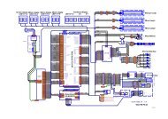
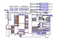
PC BOARD CONNECTIONS AND CONTROLS<br />
Volume Control<br />
Knob<br />
Stereo Audio<br />
Connector<br />
JAMMA Harness<br />
REFERENCE INFORMATION<br />
Auxiliary Cable<br />
TYPICAL CONTROL PANEL LAYOUTS FOR ‘STREET FIGHTER iii 3RD STRIKEm’
WARNINGS & NOTICES<br />
WARNING<br />
A very small portion of the population has a condition which may cause them to experience epileptic<br />
seizures or have momentary loss of consciousness when viewing certain kinds of flashing lights or<br />
patterns that are present in our daily environment <strong>The</strong>se persons may experience seizures while<br />
watching some kinds of television pictures or playing certain video games. People who have not had<br />
any previous seizures may nonetheless have an undetected epileptic condition.<br />
If you or anyone in your family has experienced symptoms linked to an epileptic condition (e.g.<br />
cpi7,,roc nr loss of a!“AJareness) irn”1”rli”tnl” ,.-n-l.!* a--* . . -L..-c-z--<br />
UUIL”, CY “I , II I 111 LularGly L,UI I~UIL YUUI pl I~ILI~I I b&ie usrrig any video games. Vve<br />
recommend that parents observe their children while they play video games. If you or your child<br />
experience the following symptoms: dizziness, altered vision, eye or muscle twitching, involuntary<br />
movements, loss of awareness, disorientation, or convulsions, DISCONTIWE USE IMMEDIATELY<br />
WARNING<br />
Federal law provides severe civil and criminal penalties for the unauthorized reproduction,<br />
distribution, or exhibition of copyrighted audiovisual works and video games.<br />
<strong>The</strong> Federal Bureau of Investigation investigates allegations of criminal copyright infringement.<br />
NOTICE<br />
This equipment has been tested and found to comply with the limits for a Class A digital device,<br />
pursuant to Part 15 of the FCC Rules. <strong>The</strong>se limits are designed to provide reasonable protection<br />
against harmful interference when the equipment is operated in a commercial environment. This<br />
equipment generates, uses, and can radiate radio frequency energy and, if not installed and used in<br />
accordance with the instruction manual, may cause harmful interference to radio communications.<br />
Operation of this equipment in a residential area is likely to cause harmful interference, in which case<br />
the user will be required to correct the interference at his own expense.<br />
NOTICE<br />
Information in this manual is subject to change without notice. CAPCOM COIN-OP, INC. reserves the<br />
right to make improvements in equipment function. design, or components as progress in engineering<br />
or manufacturing methods may warrant.<br />
NOTICE<br />
No part of this publication may be reproduced by any mechanical, photographic, or electronic process.<br />
or in the form of a photographic recording, nor may be transmitted, or otherwise copied for public or<br />
private use, without permission from the publisher.<br />
W@<br />
A P<br />
475 Oakmead Parkway<br />
Sunnyvale, CA 94086<br />
Phone: (408) 774-0500<br />
Fax: (408) 522-5331<br />
COIN-OP, INC.<br />
Copyright 0 1999 CAPCOM @ COIN-OP, INC., All Rights Reserved