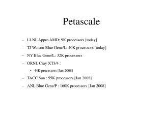
Download
1 / 23
230 likes | 237 Views
Interoperable Mesh Tools for Petascale Applications. Lori Diachin, LLNL. Representing the ITAPS Team. ITAPS focuses on interoperable meshing and geometry services for SciDAC. ITAPS Goal Improve SciDAC applications’ ability to take advantage of state-of-the-art meshing and geometry tools

E N D
Interoperable Mesh Tools for Petascale Applications Lori Diachin, LLNL Representing the ITAPS Team
ITAPS focuses on interoperable meshing and geometry services for SciDAC • ITAPS Goal • Improve SciDAC applications’ ability to take advantage of state-of-the-art meshing and geometry tools • Develop the next generation of meshing and geometry tools for petascale computing • Technology Focus Areas • Complex geometry • High quality meshes and adaptivity • Coupled phenomenon • Dynamic mesh calculations • Tera/Petascale computing
Accomplishing the ITAPS interoperability goal requires a strong team with diverse expertise Lori Diachin LLNL Ed d’Azevedo ORNL Karen Devine SNL Jim Glimm BNL/SUNY SB Bill Henshaw LLNL Ken Jansen RPI Our senior personnel are experts in complex geometry tools, mesh generation, mesh quality improvement, front tracking, partitioning, mesh refinement, PDE solvers, and working with application scientists Pat Knupp SNL Xiaolin Li SUNY SB Ahmed Khamayseh ORNL Roman Samulyak BNL Carl Ollivier-Gooch UBC Mark Shephard RPI Tim Tautges ANL Harold Trease PNNL
ITAPS will enable use of interoperable and interchangeable mesh and geometry tools • Build on successes with SciDAC-1 applications and explore new opportunities with SciDAC-2 application teams • Develop and deploy key mesh, geometry and field manipulation component services needed for petascale computing applications • Develop advanced functionality integrated services to support SciDAC application needs • Combine component services together • Unify tools with common interfaces to enable interoperability Petascale Integrated Tools Build on Component Tools Are unified by Common Interfaces
We have a suite of ITAPS services that are built on the ITAPS common interfaces AMR Front tracking Shape Optimization Solution Adaptive Loop Solution Transfer Petascale Mesh Generation Petascale Integrated Tools Build on N Front tracking Mesh Improve Mesh Adapt Swapping Interpolation Kernels Dynamic Services Geom/Mesh Services Component Tools Are unified by P P P N P Mesh Geometry Relations Field Common Interfaces P N
ITAPS technologies impact SciDAC applications in three ways • Direct use of ITAPS technology in applications • Geometry tools, mesh generation and optimization for accelerators and fusion • Mesh adaptivity for accelerators and fusion • Front tracking for astrophysics and groundwater • Partitioning techniques for accelerators and fusion • Technology advancement through demonstration and insertion of key new technology areas • Design optimization loop for accelerators (w/ TOPS) • Petascale mesh generation for accelerators • Enabling future applications with ITAPS services and interfaces • Parallel mesh-to-mesh transfer for multi-scale, multi-physics applications • Dynamic mesh services for adaptive computations Current ITAPS/TOPS/SLAC shape optimization activities will improve ILC design process
Work with the COMPASS project spans many different ITAPS service areas • Mesh Control • Correct curvilinear meshes that properly satisfy the geometric approximation requirements • Adaptive Mesh Refinement • Parallel Mesh Generation • Embedded Boundary Discretization • Partitioning Techniques • Geometry Search and Sort Beamline Absorber ILC cryomodule consisting of 8 TDR cavities
Mesh correction for curves required new technology developments Reshape • Bezier higher order mesh shape • Analytical validity determination • Determine key mesh entity causing invalidity • Curved mesh modifications for invalid elements • Reshape, split, collapse, swap and refinement Curved Region Split Curved Edge Split to Fix Model Tangency
Results allowed simulations to run faster and further than before • Initial mesh • 108k mesh regions • 250 invalid regions • Solution blows-up unless negative contribution removed • Corrected mesh • No invalid regions • Solution process and 37.8% faster (CG iterations per time step reduced) Valid curved mesh after operations 2.97M regions by correcting 1,357 invalid curved regions
Goals for curved meshes in thin sections • Thermal/Mechanical multiphysics simulations • Curved anisotropic meshes for thin sections for computational efficiency
Technology Developments • Automatically identify thin sections for complex geometry • Construct curved anisotropic layer elements with proper order
Initial results are promising; working with SLAC on use in simulation setting 2,664 tetrahedral regions Close-up of the three curved layer elements on top of the model faces To Do: Technically complex problem; may need fine-tuning in application setting Straight-sided and curved anisotropic mesh for the cell model
New area: use moving mesh refinement regions to increase computational efficiency • PIC in long structures • SciDAC codes - Pic3P/Pic2P • Isotropic refinement for defined particle domains • Coarse possible meshes for the rest domains • Pre-defined particle domain is time-dependent • Achieve computational efficiency and accuracy • Technical development • Built on the mesh modification tool(does all the mesh level work) • Define moving mesh size field with blend
Early results show significant savings New Procedure using Adaptive Controlled Mesh - 1,030,121 Regions Compared to a Uniform Mesh - 4,880,593 Regions • To Do: • Iterate to determine best use • Correct small number of poor quality elements
Parallel adaptive loop for SLAC accelerator design • Geometry defined in CAD modeler • Omega3P code from SLAC • High level modeling accuracy needed • Adaptive mesh control to provide accuracy needed • Adaptive loop runs in serial and parallel • To Do: • Initial results used file transfer; need to coordinate parallel I/O • Ensure results are satisfactory Adapted mesh (23,082,517 tets) Initial mesh (1,595 tets)
Using geometry operatorsmeans alternate solid modelers can be inserted Using ITAPS mesh operatorsmeans alternate mesh generatorsand mesh adaptation procedurescan be inserted Mesh adaptation based on local modification linkeddirectly to CAD Unaltered SLAC code Using ITAPS field operatorsallows easy construction of alternative error estimators Projection-based error estimatorused to construct new mesh sizefield given to mesh modification Error estimatorsfrom RPI and SLAC Parallel adaptive loop for SLAC uses many different software components
b1 b a2 a1 al ar bl br ra1 ra2 zcr zcc zcb zcl zcll Shape Optimization for Accelerator Cavity Design • Optimizing a cavity design is still mostly a manual process • Future accelerators employ complex cavity shapes that require optimization to improve performance • Geometry & meshing support: Fixed mesh topology: Convergence No re-meshing Re-use factorization Omega3P Sensitivity optimization ITAPS Geometry & Mesh Update Services Omega3P
Geometry Omega3P Omega3P Sensitivity ITAPS Geometry & Mesh Update Services δd, d’ Projection xr(d’)→G(d’) G(d’) ∂G/ ∂d n(xr(d’)) xr(d’) Design Velocity ∂xr / ∂G, ∂n/∂xr xr(d’) xΩ(d’) Mesh Update xr(d) xr(d) xΩ(d) • d : Design parameter vector • d’ : d + δd, new design parameters • G(d)↔xr(d) : Geometry-mesh classification • G(d’) : Geometry for parameters d’ • xr(d’), xΩ(d’) : Mesh for new iteration
Project to CAD, inverted elements New geom, old mesh Smooth Volume Smooth Surfaces Smooth Curves Services provided by ITAPS DDRIV tool • Parameterized geometric model construction • You write function which constructs model using iGeom • DDRIV acts as driver and handles IO • Coordination of mesh smoothing on geometric model • Re-classification of “old” mesh on “new” model • Target matrix-based smoothing of re-classified mesh • Computation of design velocities & embedding on mesh using iMesh Tags • To Do: • Incorporate with TOPS/SLAC optimization tools • Parallelize all aspects
Parallel Mesh Generation Needed for Petascale Simulations • Modeling long range electro-magnetic effects in the ILC requires meshes 4X – 8X current meshes • Status: • Have a prototype CAD-based parallel mesh generation capability • Demonstrated good scaling for SLAC NLC accelerator • To Do: update to production capability • Adaptive size control • Link to mesh partitioning/load balancing
Adaptive Mesh Refinement Particle Simulations Dynamic load balancing and partitioning via the Zoltan toolkit • Reduce total execution time • Distributing work evenly among processors • Reducing applications’ interprocessor communication • Keeping data movement costs low • Important in many SciDAC technologies • Adaptive mesh refinement • Particle-in-cell methods • Parallel remeshing • Linear solvers and preconditioners
Contact Information ITAPS • Web Site: www.itaps-scidac.org • Email: itaps-mgmt@lists.llnl.gov • Lori Diachin: diachin2@llnl.gov We actively seek and welcome your input!
LLNL Disclaimer and Auspices This document was prepared as an account of work sponsored by an agency of the United States Government. Neither the United States Government nor the University of California nor any of their employees, makes any warranty, express or implied, or assumes any legal liability or responsibility for the accuracy, completeness, or usefulness of any information, apparatus, product, or process disclosed, or represents that its use would not infringe privately owned rights. Reference herein to any specific commercial products, process, or service by trade name, trademark, manufacturer, or otherwise, does not necessarily constitute or imply its endorsement, recommendation, or favoring by the United States Government or the University of California. The views and opinions of authors expressed herein do not necessarily state or reflect those of the United States Government or the University of California, and shall not be used for advertising or product endorsement purposes. This work was performed under the auspices of the U.S. Department of Energy by University of California Lawrence Livermore National Laboratory under contract No. W-7405-Eng-48.