Article

Study on Breakage Characteristics and Anti-Breakage Theory for Pressure-Relieved CBM Drainage by Surface Wells in Coalbed Groups Covered by Super-Thick Pedosphere

School of Safety Science and Engineering, Anhui University of Science and Technology, Huainan 232001, China
*
Author to whom correspondence should be addressed.
Energies 2023, 16(20), 7116; https://doi.org/10.3390/en16207116
Submission received: 11 September 2023 / Revised: 2 October 2023 / Accepted: 4 October 2023 / Published: 17 October 2023
(This article belongs to the Section H: Geo-Energy)

Abstract

:
During the mining of highly gassy and low-permeability coalbed groups, massive pressure-relieved desorbed coal bed methane (CBM) is stored in the fracture zone and in the gob under the impact of mining activities. Surface wells can cross the fracture zone and the gob to drain a large amount of highly concentrated pressure-relieved CBM. CBM drainage by surface wells is an effective technology for disaster control. However, it is difficult to drill or maintain surface wells in the mining disturbance zone and overlying strata in the gob. The keyisto prevent the surface wells in the mining disturbance zone from being broken and to keep the whole surface wells unblocked. This study adopted a variety of research methods, including similar-material simulation in laboratory, numerical simulation, onsite monitoring and industrial tests. Specifically, the strata structure of surface wells for pressure-relieved CBM drainage was explored, and the characteristics of roof strata movement and stress redistribution under coalbed group mining were analyzed. Besides, positions where the surface wells are prone to breakage were found. Furthermore, based on the mechanical analysis and breakage characteristics of surface wells, the anti-breakage principle of “resistance and dodge” and the surface well completion and protection method of “upper stop and lower leak” were proposed. The proposed theory and method were then applied to pressure-relieved CBM drainage surface wells in a coalbed group covered by the super-thick pedosphere in the Huainan Coal Field. The application results indicate that the proposed theory and method succeeded in solving the breakage of surface wells and realizing the smooth transport of CBM product. The surface wells can completely resist the mining disturbance, achieving an average single-well pure CBM production of 2.71 million m3, an average service period of 482 d, and a maximum pure CBM production of 4.32 million m3.

1. Introduction

The earliest experiments on coalbed methane drainage by surface wells (CDSW) in China were conducted in No. 4 Coal Mine of Yangquan Mining Group in 1956 [1,2]. CDSW, which is a key technology for realizing the co-mining of coal and coalbed methane (CBM), has been widely adopted in highly gassy coal fields currently. According to the literatureon gas, the CDSW technology can be classified into the following two categories. (1) For highly gassy original coalbeds with high permeability, CBM is drained by surface wells which vertically enter and cross coalbeds, or vertically enter coalbeds and then change into horizontal along-measure wells [3]. (2) For pressure-relieved coalbeds subject to mining disturbance, CBM is drained by vertical surface wells, that is, surface wells cross the whole pressure-relieved coal-bearing strata to drain CBM that migrates from mining-induced fractures [4,5]. In the early 1990s, based on the successful experience of CBM development in the United States, CDSW tests were conducted in original coalbeds and pressure-relieved coalbeds of Taoyuan Coal Mine in Huaibei City, China [6]. In original coalbeds with low permeability, CBMcan be hard to drain withsurface wells. In mining-induced pressure-relieved coalbeds, CDSW is often conducted throughtraditional oil-drilling and well-completion technology. In this case, surface wells can easily break, be blocked and even lose circulation, failing to effectively accomplish their mission for a long time. They may stop producing CBM when the panel just advances over them (at most 100 m for some wells) [7]. The Texaco Company and the Enron Company from the United States conducted 12 CDSW tests in highly gassy coalbeds of thePanxie Coal Field in Huainan City, China, and none of them succeeded because the coalbed group was buried deep and covered by a super-thick pedosphere [8]. In 2005, mining-induced pressure-relieved CDSW tests were performed using the traditional oil drilling and well completion technology. Most wells failed as a result of well breakage, but some wells achieved a CBM instantaneous extraction volume of 9 m3/min in 15 days and 200 km3 in the whole drainage period [9,10,11]. In these tests, high CBM production could be achieved, since a large amount of absorbed methane had been desorbed under mining disturbance. However, CBM drainage was impeded by well breakage. If the problem of well breakage could be prevented, more pressure-relieved CBM could be drained efficiently [12,13]. Hence, for coalbed groups covered by the super-thick pedosphere, the key to efficient CDSW lies in the anti-breakage technology. Based on pressure-relieved CDSW tests conducted in Huainan and Huaibei Coal Fields in recent years, this study analyzed the breakage characteristics of surface wells in the pressure-relieved zone and explored the anti-breakage theory in this zone for the purpose of preventing such breakage.

2. Breakage Characteristics of Surface Well in the Pressure-Relieved Zone

2.1. Roof Strata Movement and Deformation Characteristics of Coalbed Group Covered by Super-Thick Pedosphere under Mining

The roof of a coalbed group is composed of several coal and rock strata with different properties. After coal mining, the immediate roof will cave when roof suspension reaches a certain limit. As the mining proceeds, relatively hard strata (normally known as key strata [14] will cave, which is called the first weighting. With the advance of the panel, key strata cave repeatedly after a certain period, forming periodic weighting in the panel. According to researches on mining subsidence and roof strata control [15,16,17], three zones, i.e., the caving zone, the fracture zone and the bending subsidence zone, exist in the gob overburden. The caving zone experiences a process of caving, reloading and compaction. The fracture zone, also referred to as the separation layer breakage zone, experiences a process of crack generation, crack growth and compaction. Both the caving zone and the fracture zone are characterized by dramatic longitudinal and transverse movements and slips between coal and rock strata, while the bending subsidence zone features the weakest movements and slips. Figure 1 shows the roof rock damage and crack growth characteristics above the returnair entry of the simulated panel [12]. With Layer AOB as an example, Section AO is in coal and rock strata, while Section OB is at the cantilever position. Layer AOB is subject to an unevenly distributed load q that comes from the overburden and the load around Point O approximates zero. This layer can be seen as a loaded cantilever beam. According to the rock damage characteristics, the layer below Layer AOB (i.e., Section CD) is under compression, while the layer above Layer AOB (i.e., Section EF) is under tension. Resultantly, Layer AOB breaks under the action of shear stress and the rock strata slip laterally. Separation layer breakage occurs when the roof strata cave and deform asynchronously (Figure 2). Specifically, strata below Layer COD cave first and break at Point O where a relatively large separation space emerges [12].

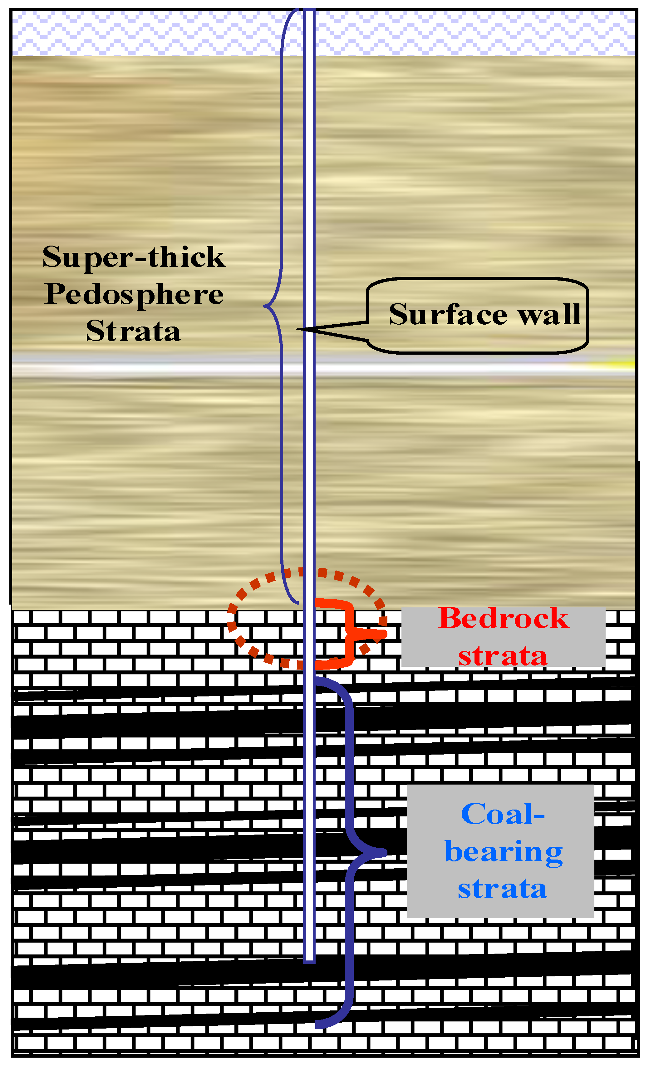
2.2. Stratum Structure around Pressure-Relieved Surface Well

The coalbeds in the Huainan and Huaibei coal fields occur in the form of a coalbed group. The coalbed group, consisting of 8–15 recoverable coalbeds, is buried at a depth of 400–1500 m and covered by pedosphere strata that are 400–600 m thick. From the surface to the recoverable coalbeds, strata fall into three sections, i.e., the pedosphere section, the bedrock section and the coal-bearing strata section (Figure 3). The pedosphere section, which mainly comprises sand, soil and water, has certain liquidity. The well body in this section exhibits strong rigidity because it is wrapped by wet soil and sand. Although the whole well body here moves laterally along with the movement of pedosphere and deviates from the vertical axis, the movement is uniform on the whole. Hence, damage barely occurs in this section. The coal-bearing strata section is mainly composed of coal and rock strata with different levels of hardness. Since this section is greatly influenced by mining and the overburden moves actively, the well body in this section can hardly resist damage movement from the overburden because it is wrapped by rock. Controlled by rock strata, the well body in this section moves along with rock strata or is broken by rock strata under the action of complex mining stress [18]. Under mining disturbance, the bedrock section moves less intensely than the coal-bearing strata section and its movement is integrated. As a result, the well body in this section is unlikely to be damaged and well completion can be achieved easily.

2.3. Breakage Positions of Pressure-Relieved Surface Well

During the mining of the first coalbed in a coalbed group, coal-bearing strata deform dramatically under the impact of mining activities. The strata above the mining stratum move unevenly, which fundamentally results in well body breakage. More than 20 pressure-relieved CBM drainage surface wells of the Huainan Coal Field were monitored in real time by the deepborehole television-logging technology and the monitoring results were compared with the core data of the wells. It was found that the breakage positions of these surface wells are closely correlated with rock properties. Under mining disturbance, the movements of pedosphere strata, bedrock strata and coal-bearing strata exhibit a certain law regarding the surface well breakage. To be specific, the pressure-relieved surface wells tend to break at two positions: the junction of pedosphere section and bedrock section and the junction of mudstone section and hard thick sandstone. In other words, the junctions of two strata whose petrophysical properties differ significantly are prone to breakage. In the caving zone and the seriously broken fracture zone where the horizontal and vertical movements of the upper and lower rock strata are dramatic and asynchronous, the surface wells are susceptible to tensile or shear damage.

2.4. Stress and Breakage Characteristics of Pressure-Relieved Surface Well

2.4.1. Breakage Characteristics of Surface Well sat the Junction of Pedosphere Section and Bedrock Section

The junction of the pedosphere section and bedrock section is exactly the position where soft and hard strata intersect. There is a delay time between roof caving and bedrock strata caving or deformation. Once the whole bedrock strata subside, the super-thick pedosphere strata above the bedrock strata subside accordingly due to their strong fluidity and weak capacity to resist deformation. This subsidence soon influences the surface and leads to basin-shaped surface subsidence. At this time, the well body deviates from the axis towards the gob side, displaying a curved shape (Figure 4). In Figure 4, the well body is fixed into bedrock strata and unable to deform. As can be observed from multiple deep-borehole television logging videos of the same well (Figure 5), the well body at the junction of the pedosphere strata and bedrock strata is influenced by a “cantilever beam effect” and can break easily. The well on the gob side moves inward under pressure (Figure 5), while the well on the other side breaks under the action of tensile stress. Consequently, the effective cross-section of the well gradually shrinks until it is blocked or broken. Once the well is broken, sands, soil and water will enter the well first and then flow into the mining space, seriously threatening safe production in the mine.

2.4.2. Tensile and Compressive Breakage

Mining disturbance leads to non-uniform strata subsidence. Resultantly, the well body tends to stretch or shorten, generating tensile or compressive stress along the axial direction. When the tensile or compressive stress exceeds the strength of casing pipes, the casing pipes may break. The axial tensile and compressive stresses mainly come from the following three sources: (1) axial tensile stress caused by strata separation; (2) axial tensile stress caused by well bending; and (3) axial compressive stress caused by water lose and compaction of pedosphere strata.
As for tensile breakage, the results of similarmaterial simulation experiments on the crack distribution of overburden after first coalbed mining in Huainan Coal Field are illustrated in Figure 6. Under mining disturbance, the stress in the caving zone and the fracture zone is redistributed, and rock strata above the gob lose abutment pressure, hence, it gradually caves. Meanwhile, the vertical stress decreases, and a horizontal stress arch is formed. The surrounding rock stress under the arch drops and the rock strata move asynchronously. The well body section between the two asynchronously moving rock strata is subject to considerable tensile impact, especially when the lower rock strata are super thick and complete. When the lower rock strata tightly wrap the well body and the weight of the lower rock strata exceeds the tensile strength of the well, the well body will experience tensile breakage. The mechanical mechanism of separation-induced tensile breakage is presented in Figure 7. Under mining disturbance, the asynchronous vertical movement of rock strata causes the generation of a separation layer. A separation layer that wraps the well body is capable of causing tensile breakage to the well body if its thickness is greater than 3 m and its hardness f is greater than 4.5.
Compressive breakage, according to the television logging video data, often occurs at the junction of pedosphere section and bedrock section. The reason is that mining-induced subsidence makes the water and sand of pedosphere strata enter the well and then flow into the mining space; subsequently, the pedosphere strata around the well body shrink due to water loss, which generates horizontal stress on the well body and results in compressive breakage. The television logging image recording compressive breakage of the well body is given in Figure 8.

2.4.3. Shear Breakage

Slip dislocation occurs between the caving zone and the fracture zone. According to onsite television logging images, generally, lower rock strata undergo horizontal slip dislocation first. Afterwards, the well body in two rock strata moves continuously along with slip dislocation of the lower rock strata, generating concentrated shear stress at the junction of the slip dislocation and thereby causing slip-shear breakage to the well body [19]. Mechanical analysis on shear breakage is shown in Figure 9; the characteristics of shearing breakage are depicted in Figure 10a; and the television logging image recording shear breakage of the well body is provided in Figure 10b.

3. Anti-Breakage Theory and Method

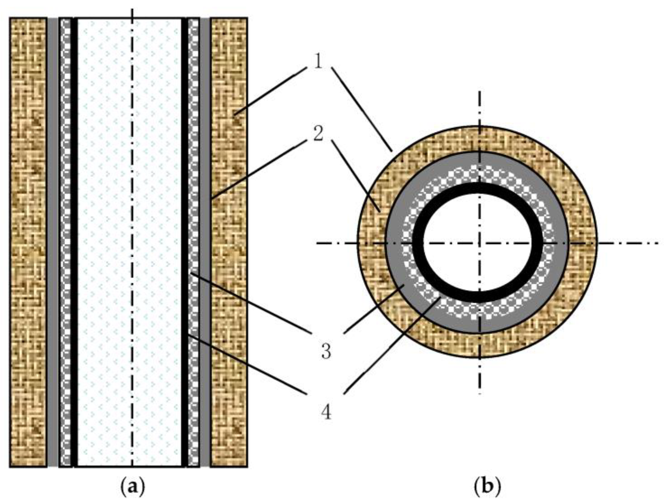
3.1. Structures and Functions of the Well Body

Pressure-relieved CBM drainage surface wells can be divided into the production section and the transport section in accordance with their functions. The production section refers to the well body that is completely in the coal-bearing strata, while the transport section is the well body in the pedosphere strata and the bedrock strata. The production section must be connected with the whole coal-bearing strata for the purpose of ensuring that the pressure-relieved CBM of the coal-bearing strata can enter this section smoothly [20]. In the transport section, the well diameter should be large enough for ensuring an effective ventilation area; besides, the well should be separated from the pedosphere strata and the bedrock strata, and no entrance of water, sand or soil is allowed; otherwise, the well may be blocked. Considering the different breakage types and degrees in different strata sections as well as the project cost, the whole well body is divided into the following three sections: the pedosphere strata section, the bedrock strata section and the coal-bearing strata section, whose structures and functions are introduced as follows.
As for the well body in the pedosphere strata section, the pedosphere strata are composed of sand, water, soil and gravel, so they are of a certain liquidity and flexibility. The deformation in these strata is relatively uniform. The well structure in this section should have the functions of anti-fracturing, anti-compressive breakage, waterresistance and sand prevention.
In the well body in the bedrock strata section, the well body is the most likely to break at the junction of bedrock strata and pedosphere strata; consequently, soil, sand and water may enter and block the entire gas production section and bedrock section of the well, and even cause mine flooding. Well completion in this section is faced with the following two technical problems: (1) the well structure should have the function of anti-breakage; and (2) the well body should be able to prevent water and sand in the pedosphere strata from leaking into the well or entering the mining space.
The well body in the coal-bearing strata section refers to the production section. Under the impact of mining activities, strata in this section move dramatically, so the well structure should have the function of anti-tensile failure and anti-shear failure. Moreover, the well body should have a series of small holes to ensure that the pressure-relieved CBM in the coal-bearing strata can smoothly enter the well in the production section.

3.2. “Resistance and Dodge” Anti-Breakage Theory for Pressure-Relieved Surface Well

The basic principle of “resistance” is to take advantage of the slight liquidity or flexible deformation characteristics of the pedosphere strata and depend on the high-strength well body to resist breakage caused by slow flexible deformation of the pedosphere strata. The specific method is to adopt a composite structure and fill composite materials in the double-layer case to improve the rigidity and strength of the well body (Figure 11). This method can prevent the well from bending, breaking or being compacted as a result of water loss and shrinkage of pedosphere strata.
Under mining disturbance, the bedrock and coal-bearing strata move and deform significantly. Even the toughest wells fail to resist such damage. Hence, the “dodge” method is proposed. Its basic principle is to expand the diameter of the surface well in the bedrock strata section and the coal-bearing strata section (Figure 12), so as to provide enough space (larger than strata deformation) between the inner wall of the surface well and the outer wall of the borehole. In this way, the surface well “dodges” strong deformation of the bedrock and coal-bearing strata as well as movement and deformation of rock strata in the fracture zone, which protects integrity of the well body. The “dodge” method of the well body in the bedrock and coal-bearing strata of the mining space can also prevent the well body from being axially broken and being radially sheared [21].

3.3. Principles of “Upper Stop and Lower Leak” to Protect Wells

The basic principle of “upper stop” is to prevent water and sand leakage, since the pedosphere and bedrock strata are of different mechanical properties, their junction is usually the entrance of sand, water and soil into the mining space. The key to efficient CDSW is to ensure a tight fix between the well body and the bedrock strata and to prevent sand from leaking into the mining space [21,22]. As illustrated in Figure 12, the well in the pedosphere strata section adopts a double-layer case filled with composite filling materials, which is the “resistance” anti-breakage well structure;consequently, the well in the pedosphere strata bedrock and coal-bearing section adopts the “dodge” structure. The basic principle of “upper stop” is to prevent water and sand leakage. The production section and the transport section are connected with “plate water sealing device”, “high-pressure slurry stop device”, “cut-off valve” and “buoyancy tube” (Figure 13). On the one hand, the well body in this section and the bedrock strata are tightly connected. On the other hand, the production section and the transport section are connected flexibly. In this way, sand, water and soil in the pedosphere strata can be prevented from entering the well body, thus realizing “upper stop”.
The principle of “lower leak” is to avoid blockage to ensure smooth connection. To ensure CBM in the coal-bearing strata can smoothly enter the production section, the well shouldbe unblocked and connected with the whole coal-bearing strata. Both breakage and blockage by sand and soil should be prevented. Specifically, the diameter of the surface well in the bedrock strata section and the coal-bearing strata section should be expanded; besides, the wall of the surface well in the coal-bearing strata section should have many small holes and be well connected with the mining space. In this way, water, sand and soil can leak into the gob through the space between the inner wall of the surface well and the outer wall of the borehole, hence realizing “lower leak”.

4. Experiments

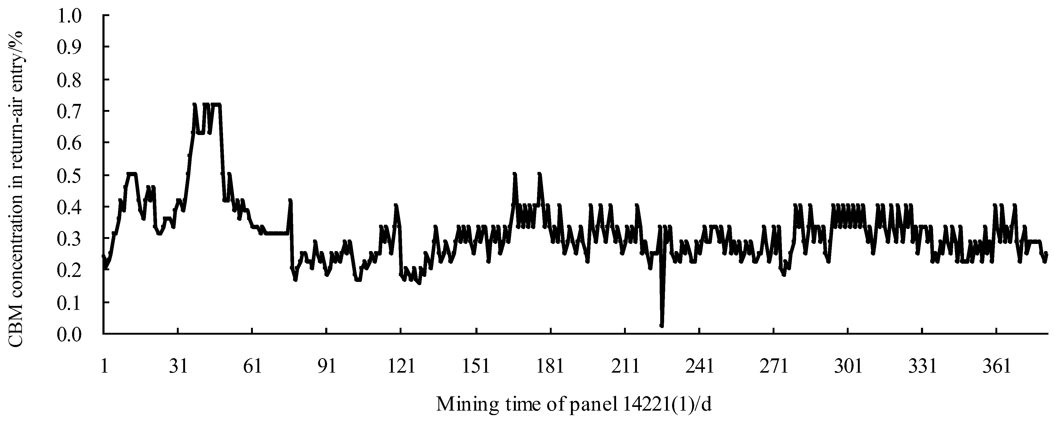
4.1. Overview of Experimental Panel

The main mining coalbeds Dingji Coal Mine are No. 13-1, No. 13-2 and No. 8 coalbeds. No. 11-2 coalbed, with stable occurrence, an average thickness of 2.19 m and an angle of 5–15°, is mined by the 1422(1) panel. This panel, with a dip length of 240 m, a strike length of 1830 m and a pedosphere strata thickness of 347–564 m, belongs to a lower protective seam mining panel. It adopts the strike retreating longwall fully mechanized mining technology and U-shaped ventilation, and its roof is controlled by the complete caving method. The mining started on 20 April 2009 end ended on 30 April 2010.

4.2. Distribution of Surface Wells

Six surface wells weredesigned in the 1422(1) panel, namely, surface well No. 1, No. 2, No. 3, No. 4, No. 5 and No. 6. Among them, the first five surface wells are 80 m away from the track entry, 160 m from the transport entry and 260 m, 575 m, 890 m, 1205 m and 1520 m from the open-off cut. Surface well No. 6 is a 50 m surface well, 190 m from the transport entry and 775 m from the open-off cut. The distribution of surface wells is presented in Figure 14. These six surface wells were drilled in two periods. Wells 1–3 were drilled in the first period, while Nos. 4–6 were drilled in the second period. All six wells were constructed using the principle of “resistance and dodge” and the surface well completion and protection method of “upper stop and lower leak”. The basic parameters of CBM drainage surface wells in the 1422(1) panel are listed in Table 1.

5. Discussions

To investigate the CDSW effect of the 1422(1) panel, automatic measuring devices for CBM drainage were installed on both the ground drainage system and the six surface wells for real-time monitoring. The flux and concentration of drained CBM are given in Table 2. The variation of CBM concentration over time is displayed in Figure 15, and the variation of single-well pure CBM flux over time is shown in Figure 16. As can be seen from Figure 14, surface well No. 6 is arranged closer to the track entry (return-air entry) than the other five surface wells. Such an arrangement ensures thatsurface well No. 6 lies within the “annular fracture circle” above the gob of the 1422(1) panel [9,12,23]. A previous study has confirmed that a large amount of pressure-relieved CBM is concentrated as an “annular fracture circle” [1]. Hence, surface well No. 6always maintains a high concentration of CBM (over 79% on average in the whole drainage process) and is barely influenced by panel advancement. Its concentration has reached 58% by the statistical date of Table 2, and it is still producing CBM till now. Surface well No. 4, which lies within the geological structure zone, merely has an instantaneous flux of 1.75 m3/min and a concentration of 0.09% until the 114th day. After that day, this well stopped producing CBM because it was broken due to the dramatic overburden movement and deformation brought by the advancement of the 1422(1) panel. The remaining four surface wells achieved sound drainage effects. When the 1422(1) panel mining was completed, all the surface wells maintained a large flux and a high concentration of drained CBM except surface well No. 4.
According to the monitoring statistics of the six surface wells, the average single-well pure CBM flux is 2.71 million m3, the average service time is 482 d, and the maximum flux is 4.32 million m3. The 1422(1) panel completely relies on the six surface wells to drain CBM form coalbeds, rarely adopting other CBM drainage measures. According to the monitoring results, the CBM concentration in the return-air entry is stable (Figure 17), and no gas overrun accidents occur. Safe and efficient production is realized in the panel.

6. Conclusions

(1) The characteristics of overburden caving and movement in the first mining coalbed of a coalbed group under mining disturbance were studied by means of similar-material simulation and numerical calculation. In addition, the mechanical mechanism of how overburden caving and crack growth influence the surface well body was analyzed, and the characteristics of well body breakage were demonstrated. On this basis, the anti-breakage principle of “resistance and dodge” and the surface well completion and protection method of “upper stop and lower leak” was put forward. This theory and method were then applied in the CBM drainage project in a coalbed group covered by super-thick pedosphere in Huainan Coal Field. The application results demonstrate that they succeeded in solving the breakage of surface wells and realizing smooth transport of CBM product.
(2) Six surface wells were arranged in the 1422(1) panel. The wells all achieved a large flux and a high concentration of CBM, except surface well No. 4. According to the experimental results, it is more favorable to arrange surface wells near the track entry (return-air entry), that is, 1/3–1/5 of the length of panel inside the entry is the optimal position for surface well arrangement.
(3) For soft, loose, highly gassy and low-permeability coalbed groups covered by super-thick pedosphere, the main technical measure against disasters in the first coalbed mining is CBM drainage. However, the above characteristics may pose difficulty in CBM drainage. The “resistance and dodge” anti-breakage theory for CDSW and the “upper stop and lower leak” method proposed in this study can provide theoretical support and technical guarantee for efficient CDSW.

Author Contributions

Z.L.: Writing—original draft, Methodology, Funding acquisition. S.S.: Conceptualization, J.L.: Validation. F.C.: Validation. K.G.: Supervision. All authors have read and agreed to the published version of the manuscript.

Funding

This research was funded by the National Science Foundation of China (Grant No. 52074013).

Data Availability Statement

No data were used for the research described in the paper.

Conflicts of Interest

The authors declare that they have no known competing financial interests or personal relationships that could have appeared to influence the work reported in this paper.

References

  1. Liu, J. Research Status and Development Tendency of Well Location Technology of CMB Development in Mining AREA Surface Wells. Saf. Coal Mines 2013, 44, 60–63. [Google Scholar]
  2. Tu, X.G.; Wu, G.G.; Hu, G.L. Draining gas with surface boreholes. Saf. Coal Mines 1979, 6, 1–4. [Google Scholar]
  3. He, T.C.; Wang, B.Y.; Tian, Y.D. Development and issues with coal and coal-bed methane simultaneous exploitation in Jincheng mining area. J. China Coal Soc. 2014, 39, 1779–1785. [Google Scholar]
  4. Zhou, F.-B.; Xia, T.-Q.; Liu, Y.-K.; Hu, S.-Y.; Zhang, Z.-G. A calculation model for gas flow rates in surfaces boreholes extracting gas from pressure-relieved seams and gobs. J. China Coal Soc. 2010, 35, 1638–1643. [Google Scholar]
  5. Liang, Y.P. Practice of Methane Drainage by Surface Well Drillingin Huainan Mining Area. J. Min. Saf. Eng. 2007, 24, 409–413. [Google Scholar]
  6. Xu, J.L.; Qian, M.G. Study on Drainage of Relieved Methane from Overlying Coal Seam Far Away from the Protective Seam by Surface Well. J. China Univ. Min. Technol. 2000, 29, 78–81. [Google Scholar]
  7. Chen, J.H.; Hu, Q.T.; Sun, D.L. Analysis of Development Technology Models of CBM by Surface Well in Coal Mining Area. Disaster Adv. 2010, 3, 432–436. [Google Scholar]
  8. Zhou, D.C. Development Trend of CMM Surface Well Drilling Technology. China Coalbed Methane 2007, 4, 18–23. [Google Scholar]
  9. Yuan, L.; Guo, H.; Li, P.; Liang, Y.-P.; Liao, B.-C. Theory and technology of goaf gas drainage with largediametersurface boreholes. J. China Coal Soc. 2013, 38, 1–8. [Google Scholar]
  10. Xu, H.J.; Sang, S.X.; Fang, L.C.; Huang, H. Production Characteristics and the Control Factors of Surface Wells for Relieved Methane Drainage in the Huainan Mining Area. Acta Geol. Sin. A-Engl.-Ed. 2011, 85, 932–941. [Google Scholar] [CrossRef]
  11. Li, R.F.; Liang, Y.P.; Zhang, J. In fluencing factors to extraction efficiency of surface goafhole. J. China Coal Soc. 2009, 34, 942–947. [Google Scholar]
  12. Liu, Z.G.; Yuan, L.; Dai, G.L.; Shi, B.; Lu, P.; Tu, M. Study on Coal Seam Roof Gas Drainage from the Strike of Annular Fracture Areas by the Long Drill Method. Eng. Sci. 2004, 6, 32–38. [Google Scholar]
  13. Sang, S.X.; Xu, H.J.; Fang, L.C.; Li, G.; Huang, H. Stress relief coalbed methane drainage by surface vertical wells in China. Int. J. Coal Geol. 2010, 82, 196–203. [Google Scholar] [CrossRef]
  14. Qian, M.G.; Miao, X.X.; Xu, J.L. Key Stratum Theory in Ground Control; China University of Mining and Technology Press: Xuzhou, China, 2003; pp. 111–119. [Google Scholar]
  15. He, G.Q.; Yang, L.; Ling, G.D. Mining Subsidence Sciences; China University of Mining and Technology Press: Xuzhou, China, 1994; pp. 155–173. [Google Scholar]
  16. Xu, J.L.; Qian, M.G.; Jin, H.W. Application study on bed separation distribution and development in the process of strata movement. Chin. J. Geotech. Eng. 2004, 26, 632–636. [Google Scholar]
  17. Xu, J.L.; Qian, M.G.; Jin, H.W. Study on “coal and coal-bed methane simultaneous extraction” technique on the basis of strata movement. J. China Coal Soc. 2004, 29, 129–132. [Google Scholar]
  18. Han, J.Z.; Sang, S.X.; Chang, Z.Z.; Huang, H.-Z. Exploitation technology of pressure relief coalbed methane in vertical surface wells in the Huainan coal mining area. Min. Sci. Technol. 2009, 19, 25–30. [Google Scholar] [CrossRef]
  19. Sun, H.T.; Liu, D.Y.; Liang, Y.P. Key rock strata effecting analysis on surface borehole shear deformation fracture. J. Chongqing Univ. 2009, 32, 551–555. [Google Scholar]
  20. Shi, Z.J.; Zhao, Y.Z.; Qi, H.J.; Liu, J.; Hu, Z. Research and Application of Drilling Technology of Extended-reach Horizontally-intersected Well Used to Extract Coalbed Methane. Procedia Earth Planet. Sci. 2011, 3, 446–454. [Google Scholar] [CrossRef]
  21. Zhong, Y.F.; Wen, B.C.; Liu, H. Key Technologies of Ground Drilling Construction for Gas Extraction in Huainan Mining Area. Explor. Eng. Geotech. Drill. Eng. 2013, 40, 10–13. [Google Scholar]
  22. Dipanjan, M.; Pallab, K.M.; Soumen, S. Optimization of drilling parameters in Raniganj Formation, Essar coal bed Methane Block—A case study. J. Unconv. Oil Gas Resour. 2014, 6, 28–33. [Google Scholar]
  23. Karacan, C.Ö. Integration of vertical and in-seam horizontal well production analyses with stochastic geostatistical algorithms to estimate pre-mining methane drainage efficiency from coal seams: Blue Creek seam, Alabama. Int. J. Coal Geol. 2013, 114, 96–113. [Google Scholar] [CrossRef] [PubMed]
Figure 1. Mechanical principle of “annular fracture circle” formation.
Energies 16 07116 g001
Figure 2. Mechanical mechanism of separation layer formation in roof strata.
Energies 16 07116 g002
Figure 3. Schematic diagram of CBM drainage by a surface well.
Energies 16 07116 g003
Figure 4. Model of surface well breakage.
Energies 16 07116 g004
Figure 5. Characteristics of surface well breakage at the junction of bedrock strata and pedosphere strata. (a) Borehole television logging images. (b) Schematic diagram of well cross-section under horizontal force.
Energies 16 07116 g005
Figure 6. Heights of the caving and fracture zones.
Energies 16 07116 g006
Figure 7. Characteristics of tensile breakage below the separation layer. (a) Mechanical mechanism of tensile breakage by the separation layer. (b) Borehole television logging image for tensile breakage.
Energies 16 07116 g007
Figure 8. Borehole television logging image for compressive breakage.
Energies 16 07116 g008
Figure 9. Mechanical mechanism of shear breakage.
Energies 16 07116 g009
Figure 10. Characteristics of shear breakage. (a) Schematic diagram of cross-section shrinkage under shear force. (b) Borehole television logging images for shear breakage.
Energies 16 07116 g010
Figure 11. Schematic diagram of double-case pipe composite well body structure. 1—Outside cement, 2—Outside steel pipe, 3—Inside cement, 4—Inside steel pipe. (a) Vertical cross-section view. (b) Horizontal cross-section view.
Energies 16 07116 g011
Figure 12. Schematic diagram of “dodge” in the production section. 1—Coal-bearing strata, 2—Expanded hole, 3—Production section with small holes of surface well. (a) Borehole television logging image. (b) Vertical cross-section view. (c) Horizontal cross-section view.
Energies 16 07116 g012
Figure 13. Cementing system of “upper stop”. (a) Vertical cross-section view. (b) Borehole television logging images.
Energies 16 07116 g013
Figure 14. Arrangement of the six surface wells.
Energies 16 07116 g014
Figure 15. Variations of concentrations of drained CBM by surface wells in the 1422(1) panel over time.
Energies 16 07116 g015
Figure 16. Flux of drained CBM by surface wells in the 1422(1) panel over time.
Energies 16 07116 g016
Figure 17. Monitoring results of CBM concentration in the return-air entry of the 1422(1).
Energies 16 07116 g017
Table 1. Basic parameters of surface wells in the 1422(1) panel.
SN of Surface WellsDepth of PedospHere, Strata/mTotal Length of Surface Well/mPosition of Well Bottom
1484.00919.50Floor of No. 11-2 coalbed
2497.20923.52Floor of No. 11-2 coalbed
3510.10931.50Floor of No. 11-2 coalbed
4498.80929.32Floor of No. 11-2 coalbed
5501.90932.76Floor of No. 11-2 coalbed
6499.25925.00Floor of No. 11-2 coalbed
Table 2. Flux and concentrations of drained CBM of surface wells in the 1422(1) panel.
SN of Surface WellsBeginning Drainage DateEnd Drainage DateCBM Concentration
Max–Min/Average
/%
Pure Flux
Max–Min/Average
/(m3·min−1)
Total Amount of Drained CBM/m3
12 July 20098 September 201090–35/69.9011.76–1.16/3.403,119,681
214 September 20098 September 201095–46/71.666.98–1.19/2.621,496,500
318 November 200920 December 201097–25/57.3011.22–0.95/3.944,321,745
45 January 20108 May 201089–5/36.0013.33–0.41/3.60581,960
519 March 20103 August 201188–20/48.3211.72–0.89/4.112,964,361
61 January 201020 December 201198–47/79.007.90–0.89/3.143,785,630
Disclaimer/Publisher’s Note: The statements, opinions and data contained in all publications are solely those of the individual author(s) and contributor(s) and not of MDPI and/or the editor(s). MDPI and/or the editor(s) disclaim responsibility for any injury to people or property resulting from any ideas, methods, instructions or products referred to in the content.

