
Novel Non-Evaporable Getter Materials and Their Possible Use in Fusion Application for Tritium Recovery


ENEA, Fusion and Technology for Nuclear Safety and Security Department, Via E. Fermi 45, 00044 Frascati, Italy
*
Author to whom correspondence should be addressed.
Molecules 2020, 25(23), 5675; https://doi.org/10.3390/molecules25235675
Submission received: 28 October 2020
/
Revised: 26 November 2020
/
Accepted: 28 November 2020
/
Published: 1 December 2020
(This article belongs to the Special Issue Innovative Materials for Energy Storage)
Abstract
:Non-evaporable getters (NEGs) are metallic compounds of the IV group, particularly titanium and/or zirconium-based alloys and are usually used as pumps in vacuum technologies since they are able to sorb, by chemical reactions, most of the active gas molecules, with particular efficacy towards hydrogen isotopes. This work suggests an alternative application of these materials to fusion nuclear reactors, where there is the need to recover small amount of tritium from the large helium flow rate composing the primary coolant loop. Starting from the tritium mass balance inside the primary coolant loop, the amount of coolant to be routed inside the coolant purification system (CPS) is identified. Then a feasibility study, based on the bulk getter theory, is presented by considering three different commercial alloys, named ST707, ST101 and ZAO. The results provide the mass, the area and the regeneration parameters of the three different alloys necessary to fulfill the requirements of the CPS unit. By comparing the features of the three alloys, the ZAO material appears the most promising for the proposed application because it requires the lower amount of material and a lower number of regeneration cycles.
1. Introduction
Getter materials are able to chemically adsorb gas molecules on their surface, therefore are widely used in the Ultra and Extreme High Vacuum (UHV and XHV) applications. A fundamental aspect for the getter operation is the activation process necessary to create a clean surface on which the active gases (typically H2, H2O, CO, CO2, N2, O2) can react [1]. According to the procedure used to realize the active surface, getter materials can be classified in two categories: evaporable and non-evaporable getters [2]. Common getter materials used in the evaporated mode are alloys based on barium and titanium which are deposited via evaporation process to form a thin film getter. In case of non-evaporable getters (NEGs) the activation process consists of a heat treatment under dynamic vacuum or under inert (noble gases) atmosphere, in order to remove the passivation layer (mainly oxides and carbides) covering its surface by promoting their bulk diffusion. Materials used as NEGs are metal alloys of the IV group (particularly titanium and zirconium) which exhibit the following characteristics: (i) their oxides easily diffuse at high temperature, ensuring a clean and highly reactive surface and (ii) their chemical activity vs. the active gases usually present in vacuum devices is high [3,4,5]. Non-evaporable getter alloys are able to sorb, by chemical reactions, most of the active gas molecules, with particular efficacy towards hydrogen isotopes. On the contrary, rare gases are not sorbed at all, since they simply do not react. Once the getter is activated, sorption of active gas molecule occurs in a few steps: (i) the first step consists in the dissociation of gas molecules at the getter surface; (ii) dissociation is then followed by sticking of the resulting atomic species onto the getter surface (with a probability that depends on the getter material and temperature and on the nature of the particular gas), this second step always occurs for any type of active gas, though with different binding energies; (iii) the third step consists of the diffusion of adsorbed atoms from underneath the surface to the still empty part of the bulk alloy; it may or may not occur, depending on the diffusivity of each specific gas inside the metal and on the getter temperature. If surface adsorption (steps a and b) is faster than bulk diffusion, the sorption rate is limited by this latter phenomenon; similarly, when diffusion is faster, the sorption rate is limited by the surface kinetics. These two different situations are usually referred to as “diffusion-limited” and “surface-limited” sorption. Actually, when the getter is exposed to a mixture of active and noble gases, a further step should be considered, which is preliminary to the three steps described above, consisting in the diffusion of active molecules across a thin gas layer surrounding the getter surface. This process is driven by the concentration gradient of the active molecular species between the gas bulk (outside of the layer) and the getter surface [6]. The pumping speed, for each gas species, depends of course on which of all the above steps controls the rate.
As reported by Maccallini et al. [2], NEGs are widely used as pumps in industry, research and development (R&D) labs, research centers and large physics projects like accelerators, synchrotrons or fusion reactors [7,8]. Usually NEGs are preferred to others UHV and XHV systems (like turbo molecular, cryogenic or sputter-ion pumps) in those cases in which it is necessary to avoid vibration and generation of electromagnetic disturbances and when the space requirement is an issue. In addition, NEG pumps remove very efficiently hydrogen, that is one of the residual gas in UHV, they do not require any power supply during gas adsorption and they are oil-free. Due to these characteristics, novel getter materials have been recently developed to address the peculiar needs of fusion applications. An example is given by the ZAO® alloy which is under investigation as possible candidate pumping material in the neutral beam injector of the EU-DEMO (European DEMOnstration nuclear fusion power plant) [9,10]. The promising results obtained in the initial characterization campaign has fostered the possibility of using the NEGs technology and in particular ZAO alloy, for the removal of hydrogen isotopes impurities from the helium primary coolant loop [11].
This work identifies another possible application of NEGs inside the fusion technologies. As illustrated in the following, some tritium can permeate into the primary coolant of the EU-DEMO reactor and, from there, it has to be efficiently removed. The conventional process used to remove tritium impurities from the primary coolant loop relies on an oxidation step to form tritiated water followed by the capture and the subsequent processing of such water [12,13]. Without going into details, it is evident that such conventional process requires long processing time and foresees, as intermediate product, the formation of tritiated water whose radiological hazard is much higher than molecular tritium.
Using bulk getter theory, a feasibility study is carried out on three commercial NEG alloys. The results show that an appropriate dimensioning of the coolant purification system relying on the use of NEGs technology is able to ensure a tritium concentration inside the coolant loop within the allowable value.
2. The Problem of Tritium Impurities Inside the Helium Primary Coolant of DEMO Fusion Reactor
The EU-DEMO is the nearest-term fusion reactor designed to produce electricity and to operate with a closed fuel-cycle. It represents a machine between ITER, the world’s largest fusion experiment currently under construction in Cadarache [14] and the first-of-a-kind fusion power plant. The reference reaction for this kind of reactors is the one among two hydrogen isotopes, deuterium and tritium, as shown in Equation (1).
A cooling medium (helium or water) is used to remove the fusion heat and convert it into electricity. The presence of tritium in Equation (1) involves two problems: one related with its scarcity and one with its radioactivity—tritium is a low beta emitter with half-life of 12.3 years. For such reasons, DEMO must have a closed fuel-cycle to recover, process and reuse either the unburnt tritium or the tritium opportunely produced inside the breeding blanket. Particularly the breeding blanket is a region surrounding the tokamak composed of a Li-based material (there are several options under investigation for the most appropriate blanket configuration, see Reference [15] where the neutrons interact with lithium for producing tritium, see Equation (2).
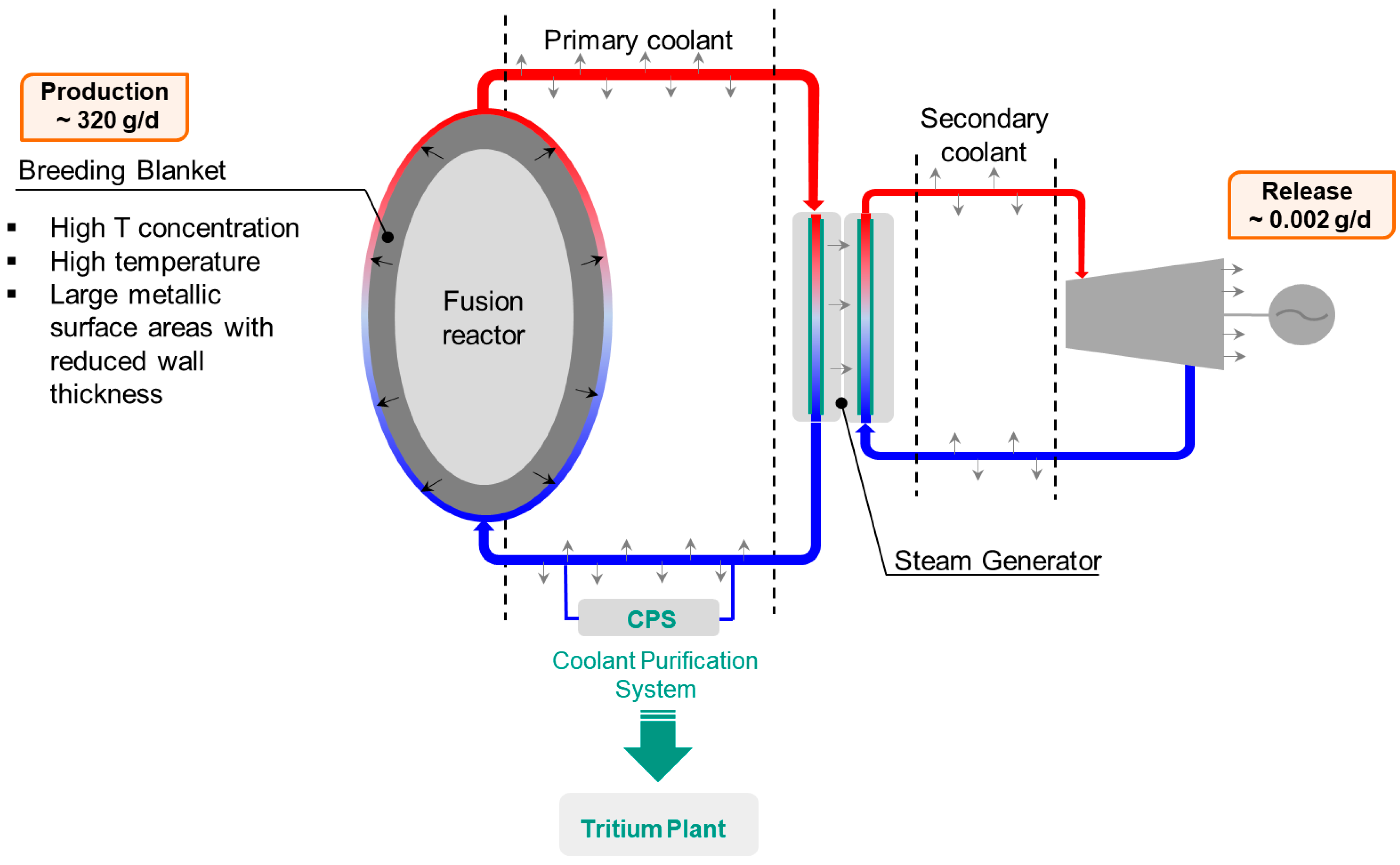
An effective breeding blanket, coupled with an efficient fuel cycle, will allow the DEMO reactor to achieve the ambitious goal of self-sufficiency, meaning that all the reacted tritium is reproduced on site. An accurate tritium control and management is fundamental also for safety aspects; it is worth to mention that the allowable tritium release into environment is currently set at 1 gr per year while the tritium produced inside the breeding blanket is about 320 gr per day—the indicated tritium production rate is referred to a DEMO design configuration having a fusion power of 1998 MW and a tritium breeding ratio of 1.05 [15]. Being the blanket the region where tritium is produced and the fusion heat is removed through the primary coolant loops, it is characterized by high tritium concentration, high temperature and large metallic surface areas with reduced wall thickness. These features promote the tritium permeation from the blanket into the primary coolant. Once in the primary coolant, the tritium can reach the working areas and the external environment through permeation and leaks. For such reasons, the primary coolant loop has to be equipped with a system, named Coolant Purification System (CPS), dedicated to the tritium removal and control. Figure 1 illustrates the tritium migration path inside the DEMO reactor.
2.1. Triitum Mass Balance Inside the Helium Primary Coolant Loop
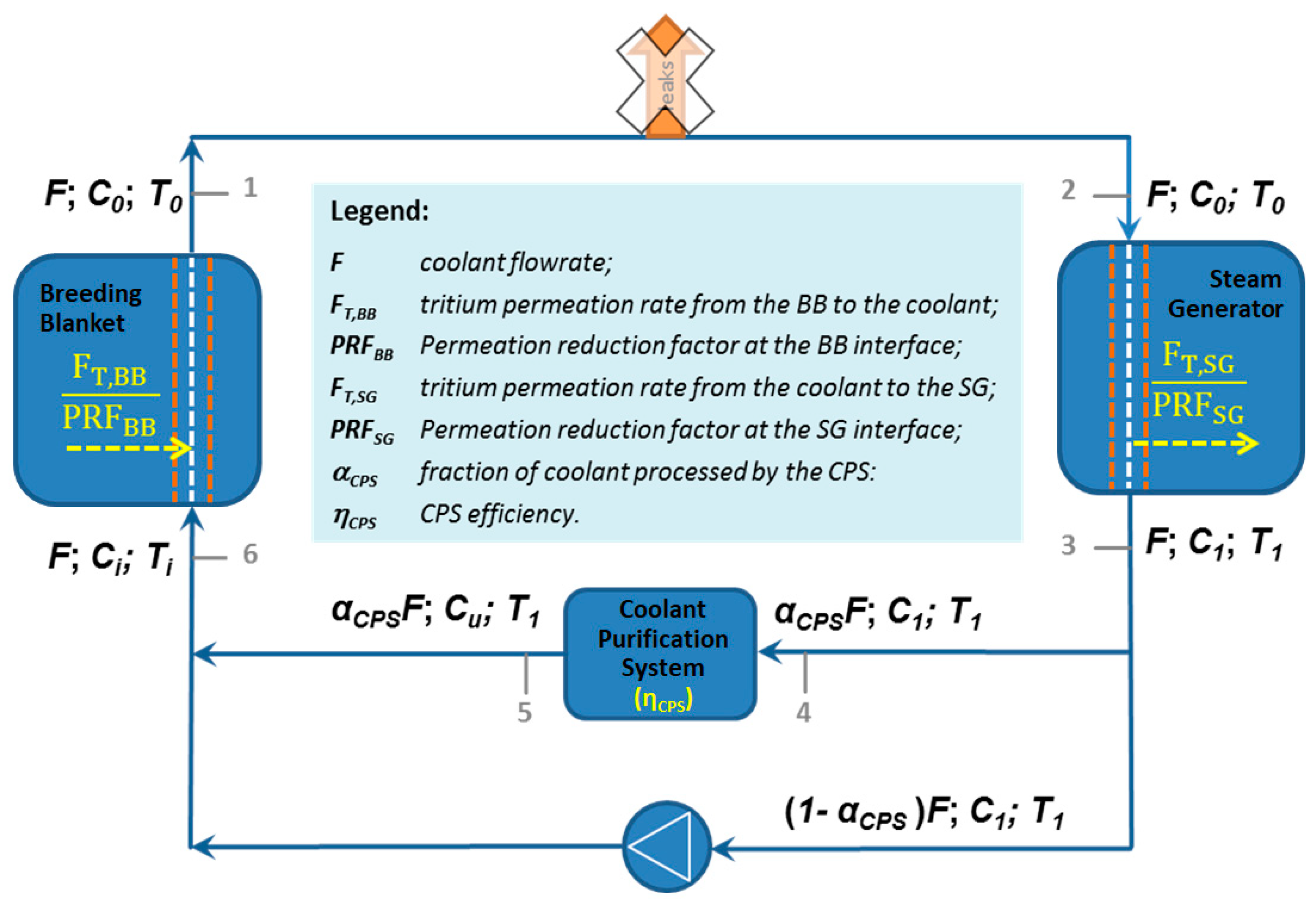
A proper design of the CPS unit requires, as first step, the definition of the tritium mass balance inside the primary coolant loop. Figure 2 provides the scheme used to assess the tritium mass balance. As showed, the CPS is placed between the Steam Generator (SG) and the Breeding Blanket (BB) and it has to treat a certain by-pass of the helium primary coolant stream (αCPS) with a given efficiency (ηCPS).
At steady state, the process can be divided into few steps, regulated by a set of mass balance equations. Starting immediately downstream of the BB (the point marked as 1 in Figure 2) and following (clockwise) the coolant flow all along the loop, it is possible to distinguish several segments:
(1-2) the coolant leaves the BB with a given flowrate F, tritium concentration C0 and temperature T0; if coolant leakages and heat losses are neglected, the coolant enters the SG with the same flowrate F, concentration C0 and temperature T0;
(2-3) while passing through the SG, the primary coolant releases heat to vaporize water in the secondary coolant loop, so that it leaves the SG at a temperature T1 < T0. Moreover, due to permeation across the SG heat exchangers, the tritium concentration in the primary coolant leaving the SG is also reduced to C1 < C0;
(3-4) a small fraction αCPS of the total coolant flowrate F, with tritium concentration C1, is sent to the CPS, while all the remaining part flows through the bypass (3-6);
(4-5) the tritium concentration in the fraction of coolant processed by the CPS is reduced to a level Cu < C1, which depends on the purification efficiency (ηCPS);
(5-6) the fraction of coolant flowing through the bypass (with a concentration C1) and that processed by the CPS, having a concentration Cu < C1, merge together upstream of the BB, resulting in a dilution of the tritium concentration at an intermediate value Ci (Cu < Ci < C1). The temperature Ti of the coolant at the inlet of the BB would be in principle lower than T1; however, if heat losses are neglected, we can assume Ti = T1;
(6-1) due to the heat release and tritium permeation from the BB, the coolant warms up and enriches in tritium concentration while passing through the BB, leaving this latter at the temperature T0 > Ti and with the tritium concentration C0 > Ci.
The mass balance equations for the above described process are:
In some cases, tritium permeation can be reduced by covering the metallic surface with dedicated coatings or by enhancing the formation of oxide layers; the efficiency of these solutions in preventing the tritium permeation is indicated with the permeation reduction factor (PRF). In a first approximation, it is possible to neglect the tritium permeation rate from the primary coolant loop into the steam generator (i.e., FT,SG = 0) and to assume the absence of antipermeation barriers in the blanket region (i.e., PRFBB = 1). Under these hypotheses, by rearranging Equations (3)–(6), the amount of coolant to be processes inside the CPS is given by Equation (7).
The above equation can be solved by considering as input that: (i) the tritium permeation rate from blanket into primary coolant (FT,BB) is approximately 0.7 g/day, as reported in Reference [16]; (ii) the tritium concentration inside the primary coolant loop has to be kept at 5 ppb (or lower) which corresponds to a pressure of 0.04 Pa, since the helium primary coolant is at 8 MPa; (iii) the efficiency of the CPS unit is estimated to be equal to 0.9. Using these inputs, the resulting coolant flow to be routed inside the CPS unit (αCPS) is about 3 kg/s.
2.2. A Coolant Purification System Based on NEGs
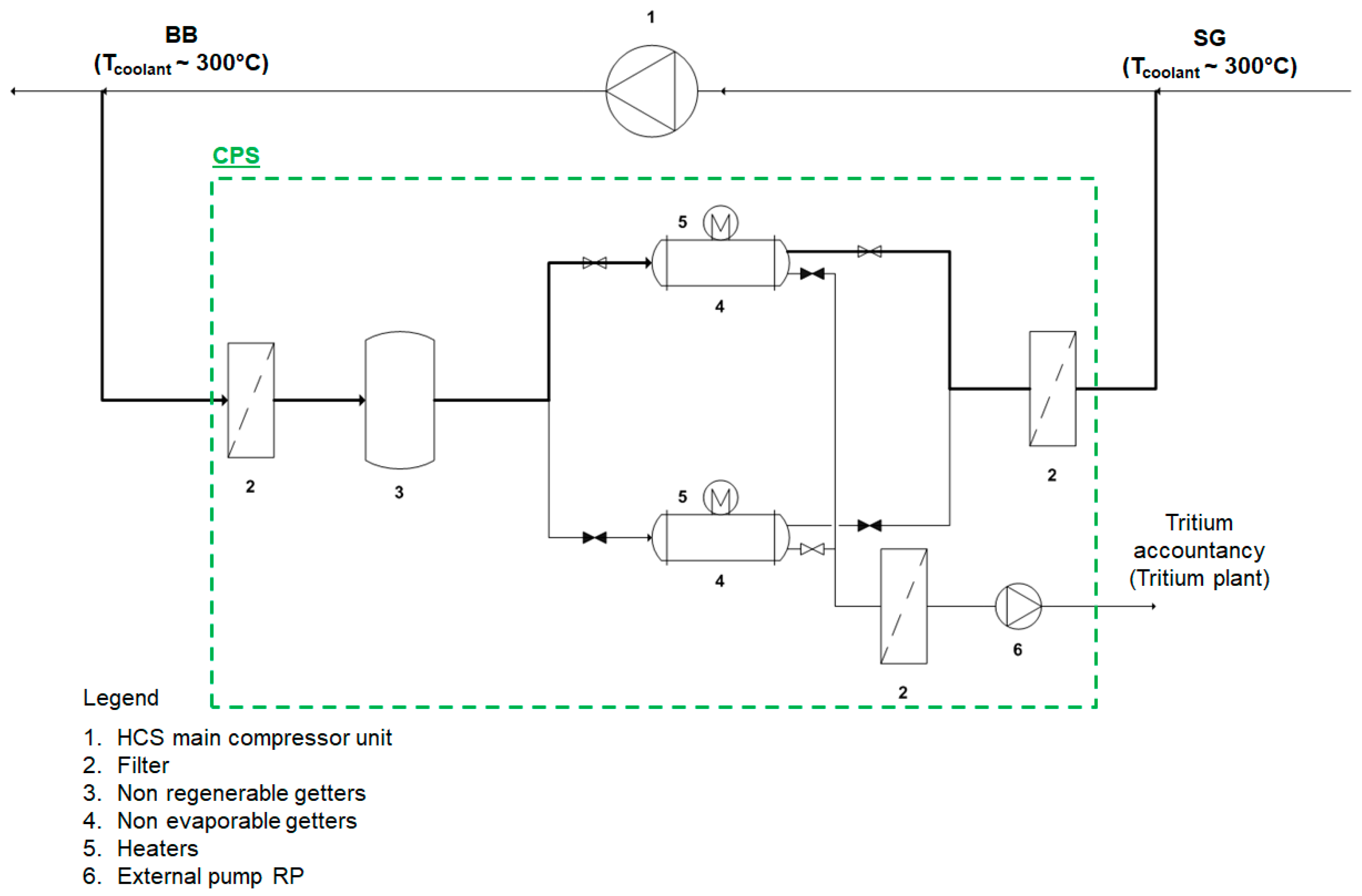
Traditional processes for removing tritium from large helium flow rates foresee three separated steps: the HT oxidation into HTO using copper oxide beds, the subsequent HTO removal by means of molecular sieve beds and the final treatment of the HTO in dedicated systems [12,13]. However, these authors have recently proposed an option for tritium recovery from primary coolant loop, based on the use of NEGs technology [17,18]. In fact, NEGs material can directly adsorb the hydrogen species over their surface. This will prevent the need of the oxidation step and also the large cost associated to the processing of tritiated water. Figure 3 illustrates the CPS layout that uses NEGs for the recovery of the hydrogen species.
The operational mode of the proposed CPS layout foresees that the slipstream of the helium primary coolant loop, at first, encounters the inlet filter for dust and solid particulates removal and series of non-regenerable getter for impurities removal, then it goes into the NEG chamber for the removal of the hydrogen species, passes through another filter and then back to the main coolant loop. As better explained in the paragraph, the getter needs to be properly regenerated, for ensuring the continuous operation of the systems, at least two NEG chambers are required, one in operation and one in regeneration mode.
3. Feasibility Study on the Use of NEGs for Tritium Recovery from Helium on DEMO CPS Scale
To support a CPS layout proposal based on NEGs, the first action is to perform a feasibility study for identifying the most suitable metal alloy to be used and the amount required to fulfill the DEMO CPS requirements. The feasibility study has been carried out in agreement with the bulk getter theory, as fully described by Knize et al. in Reference [19] and has covered these different steps: (i) selection of suitable getter alloys, (ii) definition of the sorption flux regime, (iii) dimensioning of the NEGs at DEMO CPS scale and (iv) analysis of the regeneration parameters.
3.1. Selection of Suitable Getter Alloys
The process for identifying the most suitable NEG alloy composition for a given application, surely starts with the definition of the Sieverts’ constant and of the embrittlement limit. As shown in Equation (8), the Sieverts’ constant K(T) is a function of temperature T and of A and B parameters which depend on the specific NEG alloy:
Regarding the embrittlement limit, it is worth to mention that NEG alloys are hydrides so they are subject to a progressive volume expansion during their operation and tend to flake and spall, producing small particulates. This embrittlement typically occurs when the amount of hydrogen isotopes sorbed and hence their concentration q, becomes high enough to modify the mechanical properties of the alloy. The concentration qe at which this phenomenon occurs, clearly depends on the specific getter. The sorption capacity for hydrogen (i.e., the maximum quantity of this gas that can be sorbed by a given amount of a specific getter) is therefore limited by the embrittlement phenomenon. To prevent hydrogen concentration q from reaching the limit qe, NEG pumps need to be periodically regenerated, that is, heated and held at a suitably high temperature TR (>TS) for a long enough time τR (both depending on the specific alloy) under dynamic vacuum (or under ultra-pure noble gas atmosphere) in order to release almost all the hydrogen sorbed. It is common practice to operate getters at a maximum hydrogen concentration about one half of their embrittlement limit.
Three different NEG alloys produced by the SAES group [20] have been considered. For each alloy, Table 1 illustrates the Sieverts’ parameters (A and B), the embrittlement limit (qe), the Sieverts’ constant (K(T)) and the hydrogen concentration at the getter surface (q0). Particularly K(T) and q0 have been assessed for two different temperatures (300 and 500 °C) corresponding to the temperature of the coolant before and after the steam generator. The values of q0 can be derived from Equation (9), by imposing a P0 equal to 3 × 10⁻⁴ torr (i.e., 5ppb of 8 MPa)
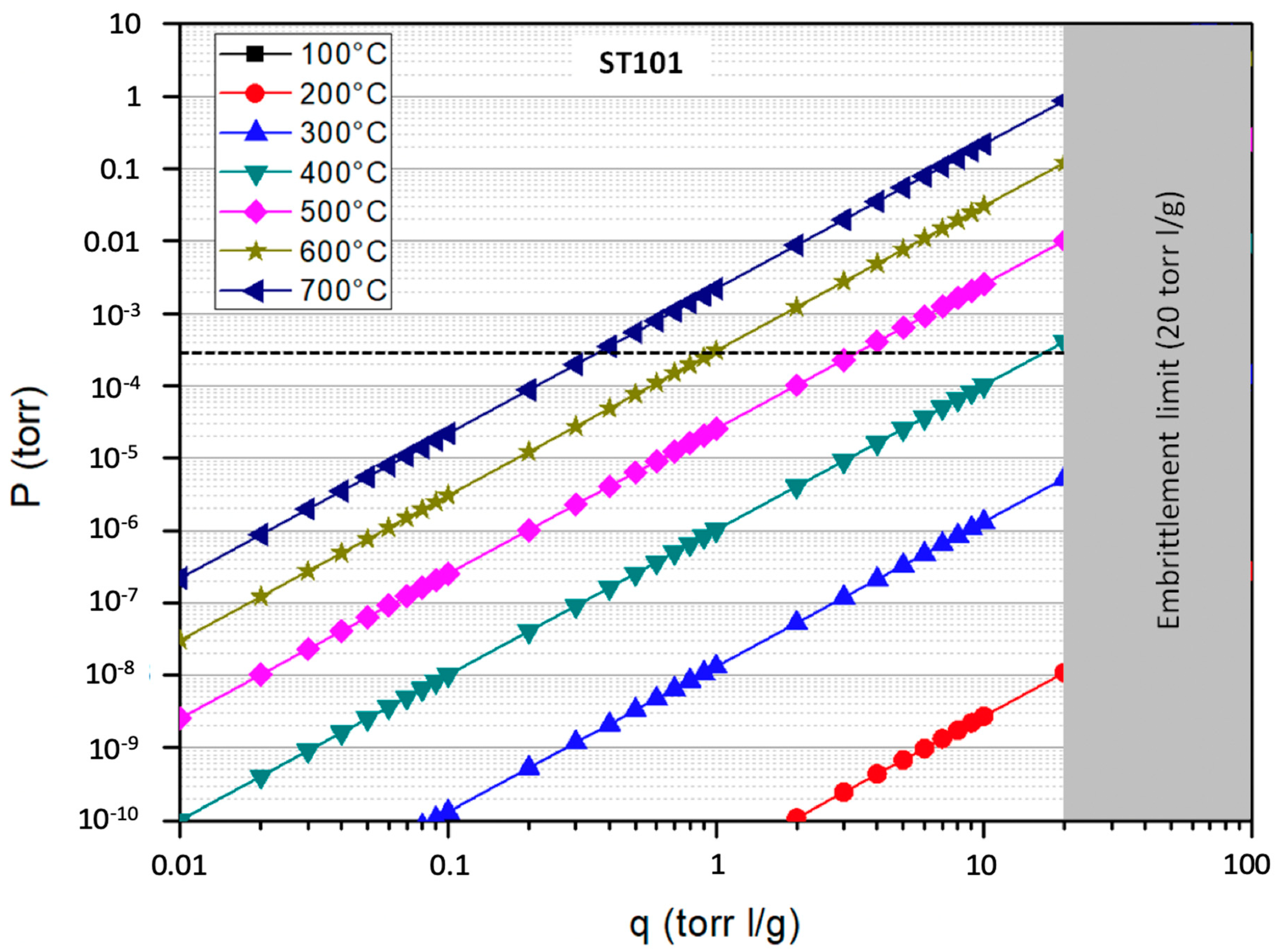
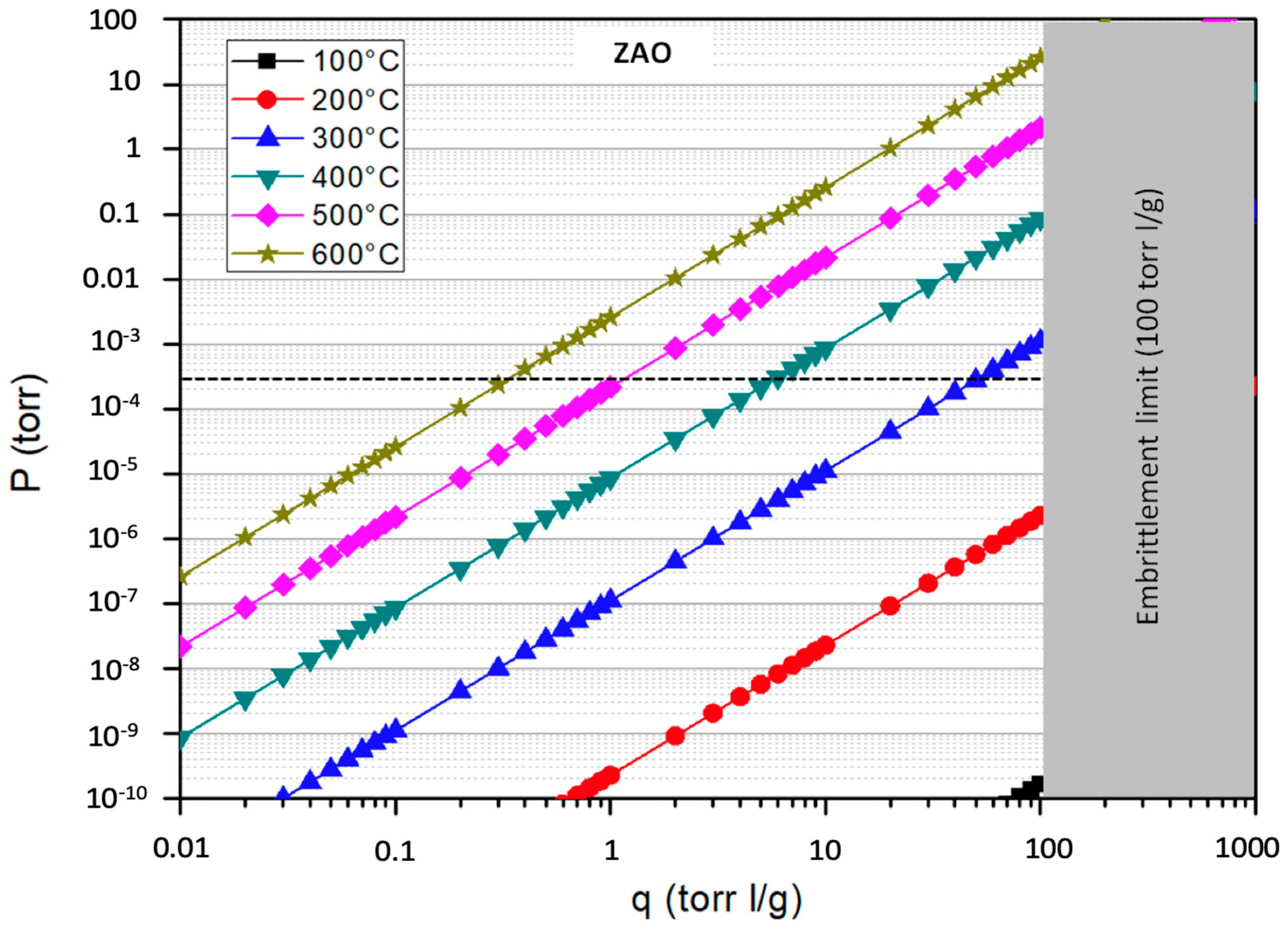
The Sieverts’ constant K(T), given by Equation (8), is a measure of the hydrogen solubility inside the getter material. Instead, Equation (9) shows that, for the same hydrogen partial pressure in the gas phase, the lowest is K(T), the highest is the hydrogen concentration that the getter can achieve. Among the getters listed in Table 1, ST101 exhibits the lowest value of K(T) and therefore the highest solubility, followed by ZAO and ST707, with ZAO that, however, has a significantly larger sorption capacity.
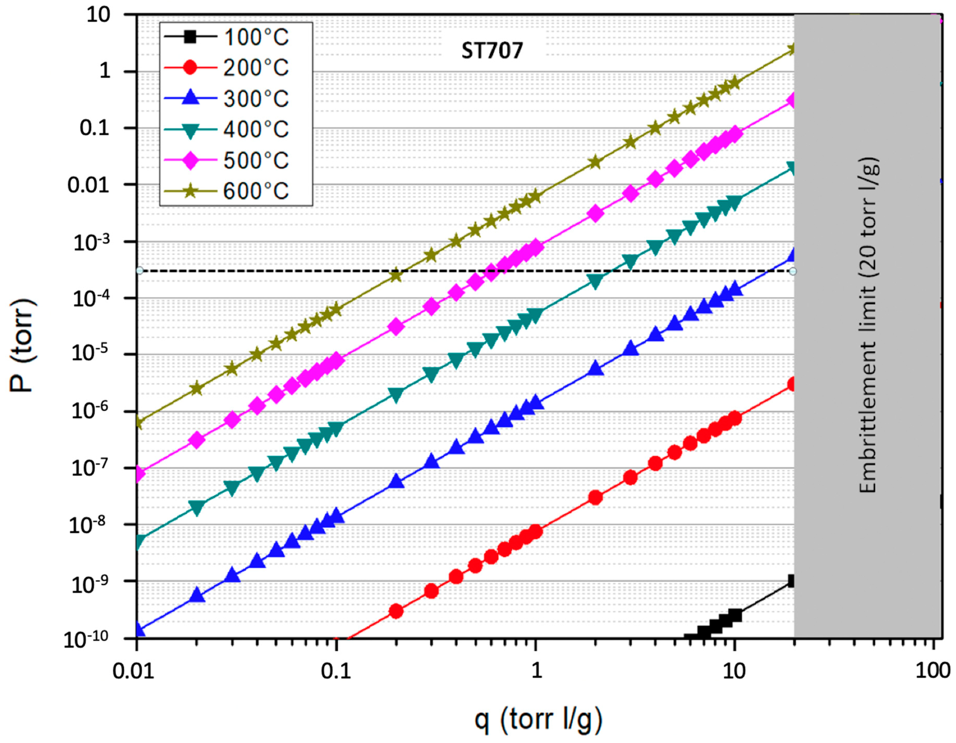
The Sieverts’ plots of the three alloys for different temperatures are reported in Figure 4, Figure 5 and Figure 6; the graphs also highlight the region above the embrittlement limit (in grey) and the value of the operative pressure (dashed line).
Common practice suggests operating the getters at an equilibrium concentration that not exceeds 50% of the embrittlement limit. Therefore, from the values reported in the Sieverts’ plots, it is possible to observe that ST707 and ZAO getters may be good candidates for a CPS located downstream of the SG where the operated temperature is about 300 °C. More precisely the sorption temperature of ST707 should be raised at a value of 320 °C to keep the tritium concentrations within this limit, that is, up to ~10 torr l/g, As for ZAO, to keep the equilibrium concentration within ~50 torr l/g, it would be sufficient to operate it at 302 °C but the difference is so small that can be neglected, so that ZAO getters can be operated at 300 °C, with no additional heating during sorption. Conversely the ST101 can be considered an option for CPS only if operated at a temperature of about 500 °C, corresponding to the coolant temperature before entering the SG.
In addition, it is important to notice that ZAO getters are particularly attractive due to their significantly higher sorption capacity (i.e., high qe value) that can grant longer operation cycles and reduce the frequency of regenerations. On the other hand, ZAO alloy represents the latest developed intermetallic compound, therefore it is still poorly characterized.
3.2. Definition of the Sorption Flux Regime
The bulk getter theory provides different approximated solutions in the two limit situations corresponding to either a “surface limited” or a “diffusion limited” sorption flux. To decide which of these two regimes governs the process, it is necessary to evaluate the dimensionless parameter H, defined as the ratio of the surface limited flux, kiP0, to the diffusion limited flux, Dc0/L, see Equation (10).
For H < 1, the sorption rate is limited by surface kinetics, whereas, for H > 1, it is governed by diffusion flux. The equilibrium concentration c0 (torr l/cm3) can be derived as follows:
where ρ is the getter density (g/cm3). The specific pumping speed ki (i.e., the pumping speed per unit surface area) may depend on the particular getter and on its form; an appropriate order of magnitude is estimated to be ~0.1 L s−1 cm−2, for all the three different getters considered. The thickness L of getter layers deposited on metal substrate is typically ~100 µm. The diffusivity, D(T) in cm2/s, of hydrogen isotopes inside the bulk getter can be expressed in the Arrhenius form as:
The parameters α and β in Equation (12) depend on both the specific alloy and the gettered species, so, for the same getter, they are different for protium, deuterium and tritium. Data reported in literature for ST101 [21] and ST707 [22], are summarized in Table 2. Unfortunately, no data are available for tritium, so the same diffusivity of deuterium is assumed.
Regarding the ZAO alloy, since its characterization is still ongoing, α and β values are still under assessment. The information about its diffusion coefficient (D) at 300 °C has been provided to the authors directly by the SAES group.
The input values and the results of calculations aimed at estimating the dimensionless parameter H for the three alloys are summarized in Table 3.
In all cases H << 1 so, as expected, the sorption flux is limited by surface kinetics. Therefore, according with the bulk getter theory [19], the adsorption rate ΓD (T,t) (in torr l s−1 cm−2) of a certain alloy can be approximated by Equation (13).
Since during the regeneration phase, the temperatures are higher than during sorption, the diffusivity is expected to further increase resulting in a reduction of the dimensionless parameter H. Therefore, the surface limited regime applies also in the regeneration phase. The sorption regime has been assessed using the diffusivity of deuterium. According to mass scaling law, the diffusivity of tritium is expected to be slightly lower, thus resulting in a marginally higher value of the dimensional parameter H, whose value for deuterium, however, is much lower than 1. We can therefore conclude that the sorption flux will be limited by surface kinetics even in the case of tritium.
3.3. Dimensioning of the NEGs at DEMO CPS Scale
Referring to the proposal of a coolant purification system for the DEMO reactor based on the use of NEGs (see Figure 2), the required mass (M) and area (AG) of a certain getter can be defined by fixing the follow boundary conditions: (i) at steady state, the amount of tritium () extracted per unit time from the getter surface should be equal to the amount of tritium that permeates from the blanket region into the primary coolant loop (see Equation (14)); (ii) too frequent regeneration cycles should be avoided, therefore the sorption time (τS) should be at least greater than 1 day.
For a given τS, the amount of tritium adsorbed is provided by Equation (15).
Obviously, the mass of the getter (M) can be expressed as:
By combining Equations (14)–(16), it is possible to identify the mass and the area required for a given getter alloy (see Equations (17) and (18)).
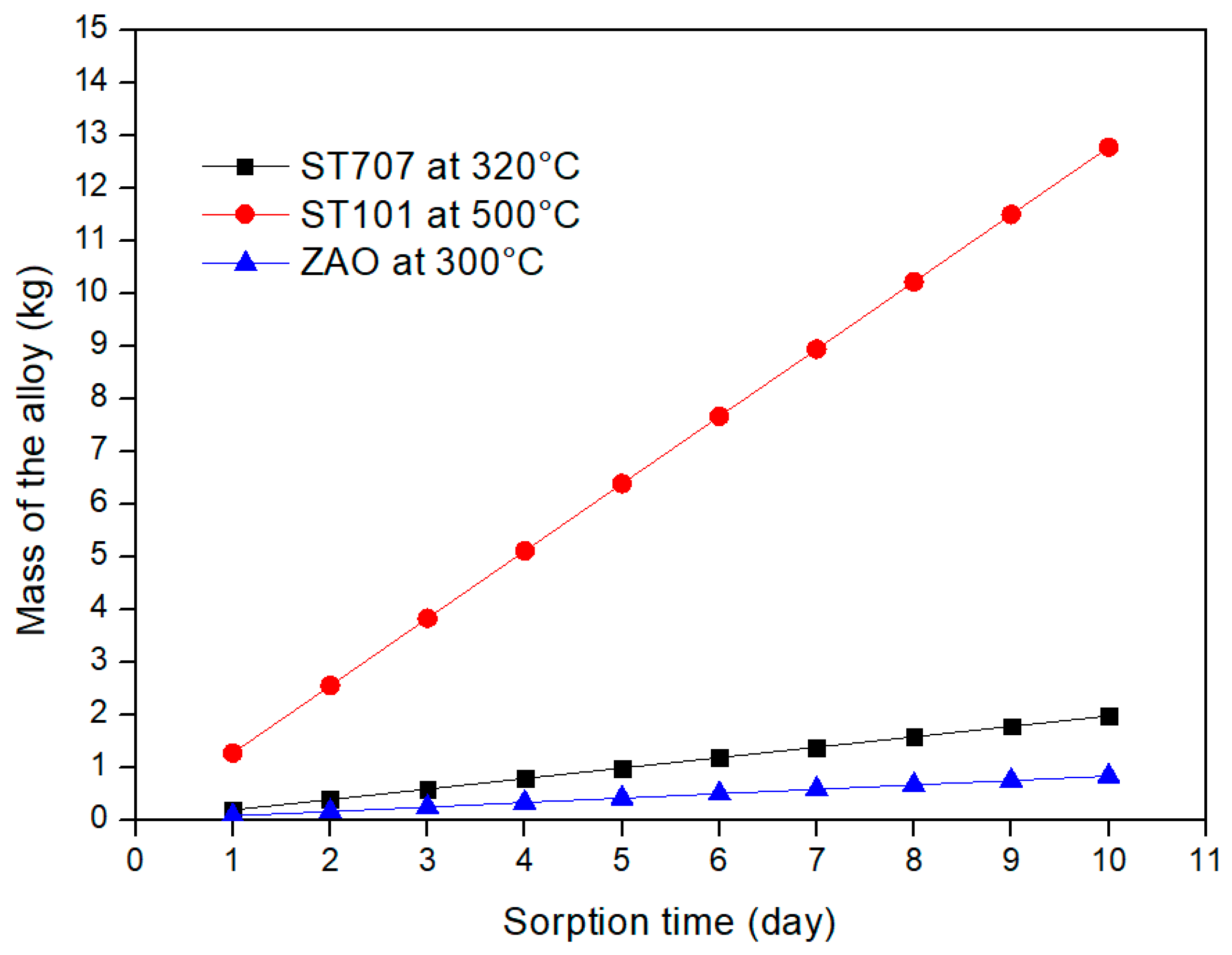
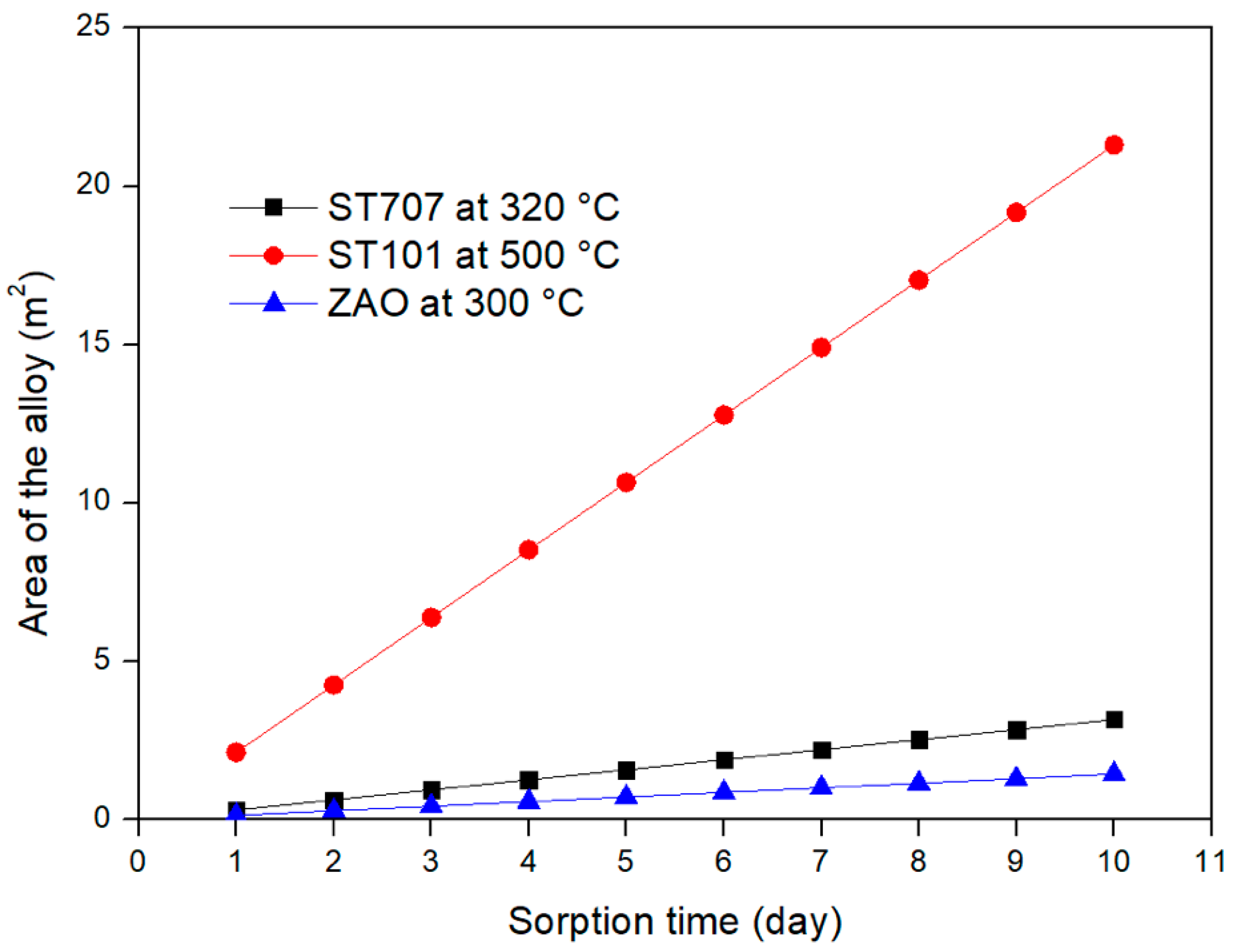
For the three different alloys considered in this study, Figure 7 and Figure 8 provide the mass and the area required to fulfill the DEMO CPS requirements by considering a sorption time range between 1 and 10 days. The results clearly show that a DEMO CPS unit relying on the use of the ZAO alloy is the one that requires the lowest mass and area of the getter materials.
3.4. Analysis of NEGs Regeneration Parameters
To complete the feasibility study of NEGs for DEMO CPS application, the final aspect to be defined is related to the regeneration time (τreg). Indeed, NEGs are storage pumps with a finite capacity, that can accumulate hydrogen into their bulk until they saturate. In order to release almost all the hydrogen sorbed and become ready for a new sorption cycle, getters need to be periodically regenerated at a temperature TR higher than the sorption temperature TS. Therefore, to provide continuous operation, the CPS unit must be equipped with two (or more) getter beds, to ensure that, at any time, there is always one unit in operation, while the other(s) is(are) being regenerated. The overall time τreg required to regenerate a getter, is given by the sum:
where τW is the warm-up time, during which the temperature of the alloy is raised gradually (to avoid excessive thermal and mechanical stress) from TS to TR, τR is the length of the regeneration plateau at constant temperature TR and τC is the cool-down time, during which the temperature is reduced from TR to TS. In practice, the regeneration starts soon after the end of a sorption cycle, when the getter has achieved equilibrium with tritium in the gas phase at a partial pressure P0, so that the initial concentration in the getter, at the beginning of the regeneration plateau, is ~q0, given by Equation (9) for T = TS. Similarly, at the end of the regeneration plateau, the residual tritium concentration in the getter must be equal to qi, where qi << q0. The required time span of the regeneration plateau (i.e., the time needed to reduce the hydrogen concentration inside the getter from the initial value q0 to the final value qi), is given by:
and depends on both qi and q0, as well as on the getter mass M, on the regeneration temperature TR and on the effective pumping speed ST of the external pump.
In the following, different values of the regeneration temperature TR have been considered and the corresponding values of the diffusivity D(TR), of the Sieverts’ constant K(TR) and of the warm-up time τW, have been calculated. In particular for the warm-up time, τW, has been estimated assuming a warm-up rate of 2 °C/min. The results obtained for the three different alloys are reported in Table 4, Table 5 and Table 6.
Finally, the required length τR of the regeneration plateau have been calculated by considering a pumping speed S of the external backup pump of 1000 l/s and by imposing different values (from 0.1 down to 0.0001 torr l/g) for the final tritium concentration (qi) inside the three alloys at the end of the regeneration procedure. τ0 is defined as:
As above, the calculations have considered different values of the regeneration temperature TR. The results obtained for the ST707, ST101 and the ZAO alloys are reported in Table 7, Table 8 and Table 9, respectively. Evidently, τ0 represents the time available, after the end of the regeneration plateau, for reducing the getter temperature from TR to TS and become ready, within the time τS, for a new sorption cycle. Negative values of τ0 indicate that the sum of the warm-up time τW and of the regeneration plateau τR is longer than a sorption cycle τS; this means that more than two getter beds have to be provided for ensuring the continuous operation of the CPS. Conversely, positive values of τ0 indicate that there is still some time available, after the end of the regeneration plateau, to allow for the cool-down phase (τC). However, since this latter usually proceeds at a lower rate compared to warm-up, τC is expected to be longer (possibly of up to a few times) compared to τW. For ensuring the continuous operation of the CPS unit composed of only two getter beds, τ0 must be longer than τC, therefore the only cases of interest are those where τ0 is several times higher than τW.
For the case in which the final tritium concentration, qi, inside the getter at the end of the regeneration procedure is set at 0.1 torr l/g, the results show that the lowest regeneration temperature considered for the three alloys (i.e., 650 °C for ST101 and 550 °C for ST 707 and ZAO) will allow to operate the CPS unit with only two getter beds. However it is important to notice that, for the case of ST707 and ST101, the results reported in Table 7 and Table 8 are obtained by considering a sorption time of 5 days (τS = 5 days) while for the ZAO alloy, due to its significant larger sorption capacity, it has been possible to consider a longer sorption time (τS = 10 days).
4. Discussion and Conclusions
This paper investigates an alternative application of the NEGs which are normally utilized in vacuum systems. The proposed application foresees the use of NEGs inside the coolant purification system of the EU DEMO reactor where a certain amount of tritium has to be removed from the primary coolant loop. Firstly the requirements of the coolant purification system have been defined. It has been assessed that about 3 kg/s of helium has to be continuously processed in order to maintain the tritium concentration inside the coolant loop at the value of 3 × 10⁻⁴ torr (5ppb). Then a feasibility study involving three different commercial getter alloys (ST707, ST101 and ZAO) from the SAES group has been conducted. According to the assessed Sieverts’ plot, the embrittlement limit and the operative pressure, the most appropriate sorption temperature for each alloys has been identified. Particularly the ST707 can be operated at 320 °C, the ST101 at 500 °C and the ZAO at 300 °C. Being the temperature of the helium coolant about 500 °C before entering the steam generator and about 300 °C when leaving, the ST101 can be considered an option for a CPS unit placed upstream the heat exchanger while the ST707 and ZAO are considered for an application downstream the heat exchanger. In such a way an additional heating of the getter during the sorption phase is not necessary. Then, after having verified that the sorption flux is surface-limited, the mass and the area of each alloy necessary to fulfill the CPS requirements have been assessed. By considering a sorption time of 5 days the required mass and area of the ST707 are about 1 kg and 1.6 m2, while for the ST101 are 6.4 kg and 10.6 m2. Since the ZAO alloy is characterized by a larger sorption capacity and an higher embrittlement limit, a longer sorption time has been considered; with a τS of 10 days the mass and the area necessary for the ZAO alloy are 0.8 kg and 1.5 m2, respectively. Finally the regeneration parameters have been evaluated by assuming different regeneration temperatures. This last evaluation has demonstrated that, under the investigated conditions, all the three alloys allow the operation of the CPS unit with two getter beds (one in operation and one in regeneration).
In conclusion, this study has demonstrated that the use of NEGs for the proposed application is feasible. Among the three alloys considered, the ZAO is the one that exhibits the best performances since it ensures longer sorption time, thus lower regeneration cycles. However the ZAO is a very recent material and requires additional experiments, particularly hydrogen diffusion parameters still need to be properly defined and adsorption/desorption parameters need to be assessed for the three hydrogen isotopes. In addition, future activities will be devoted to investigating the most appropriate NEG configuration. Traditional processes used for removing small amount of tritium from large helium flow rate foresee its oxidation into tritiated water that needs opportunely treated at a later stage. A great advantage of the proposed solution is that such oxidation stage is completely avoided.
Author Contributions
Conceptualization, A.F. and A.S.; methodology, A.F. and A.S.; formal analysis, A.S. and A.F.; writing—original draft preparation, A.S.; writing—review and editing, A.S., A.F., L.F. and S.T.; project administration, A.S. and S.T.; funding acquisition, A.S. and S.T. All authors have read and agreed to the published version of the manuscript.
Funding
This work has been carried out within the framework of the EUROfusion Consortium and has received funding from the Euratom research and training programme 2014–2018 and 2019–2020 under grant agreement No 633053. The views and opinions expressed herein do not necessarily reflect those of the European Commission. The APC was funded by MDPI.
Conflicts of Interest
The authors declare no conflict of interest.
References
- Ferrario, C. Chemical pumping in vacuum technology. Vacuum 1996, 47, 363–370. [Google Scholar]
- Maccallini, E.; Siviero, F.; Bonucci, A.; Conte, A. Non evaporable getter (NEG) technology: A powerful tool for UHV-XHV systems. Aip. Conf. Proc. 2012, 2, 1451. [Google Scholar]
- Benvenuti, C.; Chiggiato, P.; Costa Pinto, P.; Escudeiro Santana, A.; Hedley, T.; Mongelluzzo, A.; Ruzinov, V.; Wevers, I. Vacuum properties of TiZrV non-evaporable getter films. Vacuum 2001, 60, 57–65. [Google Scholar]
- Bourim, E.M.; Kim, H.Y.; Chung, N.K. Development and Characterization of Non-Evaporable Getter Thin Films with Ru Seeding Layer for MEMS Applications. Micromachines 2018, 9, 490. [Google Scholar] [CrossRef] [PubMed] [Green Version]
- Benvenuti, C.; Chiggiato, P.; Mongelluzzo, A.; Prodromides, A.; Ruzinov, V.; Scheuerlein, C.; Taborelli, M. Influence of the elemental composition and crystal structure on the vacuum properties of Ti-Zr-V non evaporable getter films. J. Vac. Sci. Technol. A. 2011, 19, 2925. [Google Scholar] [CrossRef] [Green Version]
- Chung, H.-K.; Dalgarno, A. Diffusion of hydrogen atoms in helium gas and helium atoms in hydrogen gas. Phys. Rev. A 2002, 66, 012712. [Google Scholar] [CrossRef]
- Chiggiato, P.; Costa Pinto, P. Ti-Zr-V non-evaporable getter films: From development to large scale production for the Large Hadron Collider. Thin Solid Films 2006, 515, 382–388. [Google Scholar] [CrossRef] [Green Version]
- Detian, L.; Yongjun, C. Application of non evaporable getter pump in vacuum metrology. Vacuum 2011, 85, 739–743. [Google Scholar] [CrossRef]
- Siviero, F.; Caruso, L.; Porcelli, T.; Mura, M.; Maccallini, E.; Manini, P.; Sartori, E.; Siragusa, M.; Day, C.; Sonato, P. Characterization of ZAO® sintered getter material for use in fusion applications. Fusion Eng. Des. 2019, 146, 1729–1732. [Google Scholar] [CrossRef]
- Siragusa, M.; Sonato, P.; Visentin, M.; Mura, M.; Siviero, F.; Viale, L.; Maccallini, E.; Day, C.; Hanke, S.; Sartori, E. Conceptual design of scalable vacuum pump to validate sintered getter technology for future NBI application. Fusion Eng. Des. 2019, 146, 87–90. [Google Scholar] [CrossRef]
- Cismondi, F.; Spagnuolo, G.A.; Boccaccini, L.V.; Chiovaro, P.; Ciattaglia, S.; Cristescu, I.; Day, C.; Del Nevo, A.; Di Maio, P.A.; Federici, G.; et al. Progress of the conceptual design of the European DEMO breeding blanket, tritium extraction and coolant purification systems. Fusion Eng. Des. 2020, 157, 111640. [Google Scholar] [CrossRef] [Green Version]
- Ciampichetti, A.; Aiello, A.; Coccoluto, G.; Ricapito, I.; Liger, K.; Demange, D.; Moreno, C. The coolant purification system of the European test blanket modules: Preliminary design. Fusion Eng. Des. 2010, 85, 2033–2039. [Google Scholar] [CrossRef]
- Tincani, A.; Aiello, A.; Ferrucci, B.; Granieri, M.; Voukelatou, K.; Ricapiyo, I.; Galabert, J.; Ortiz, C.; Arena, P.; Di MAio, A.; et al. Conceptual design of the enhanced coolant purification systems for the European HCLL and HCPB test blanket modules. Fusion Eng. Des. 2019, 146, 365–368. [Google Scholar] [CrossRef]
- The ITER Project. Available online: https://www.iter.org/ (accessed on 8 October 2020).
- Federici, G.; Boccaccini, L.V.; Cismondi, F.; Gasparotto, M.; Poitevin, Y.; Ricapito, I. An overview of the EU breeding blanket design strategy as an integral part of the DEMO design effort. Fusion Eng. Des. 2019, 141, 30–42. [Google Scholar] [CrossRef]
- Carella, E.; Moreno, C.; Urgorri, F.R.; Rapisarda, D.; Ibarra, A. Tritium modelling in HCPB breeder blanket at a system level. Fusion Eng. Des. 2017, 124, 687–691. [Google Scholar] [CrossRef]
- Santucci, A.; Frattolillo, A.; Incelli, M.; Tosti, S. The coolant purification system in DEMO: Interfaces and requirements. Fusion Eng. Des. 2017, 124, 744–747. [Google Scholar] [CrossRef]
- Santucci, A.; Incelli, M.; Noschese, L.; Moreno, C.; Di Fonzo, F.; Tosti, S.; Day, C. The issue of tritium in DEMO primary coolant and mitigation strategies. Fusion Eng. Des. 2020, 158, 111759. [Google Scholar] [CrossRef]
- Knize, R.J.; Cecchi, J.L. Theory of bulk gettering. J. Appl. Phys. 1983, 54, 3183–3189. [Google Scholar] [CrossRef]
- The SAES Group. Available online: https://www.saesgetters.com (accessed on 13 October 2020).
- Knize, R.J.; Cecchi, J.L. Diffusion of hydrogen and deuterium in Zr-Al. J. Nucl. Mater. 1982, 112, 645–647. [Google Scholar] [CrossRef]
- Knize, R.J.; Stanton, J.L.; Cecchi, J.L. Diffusion of hydrogen and deuterium in ZrVFe. J. Nucl. Mater. 1984, 123, 1553–1557. [Google Scholar] [CrossRef]
Sample Availability: Not available. |
Figure 1.
Simplified scheme of the coolant loop and Coolant Purification System (CPS) used for tritium mass balance.
Figure 1.
Simplified scheme of the coolant loop and Coolant Purification System (CPS) used for tritium mass balance.

Figure 2.
Simplified scheme of the coolant loop and CPS used for tritium mass balance.

Figure 3.
Scheme of the CPS pre-conceptual design based on novel Non-Evaporable Getter material.

Figure 4.
Sieverts’ plot of the ST707 alloy.

Figure 5.
Sieverts’ plot of the ST101 alloy.

Figure 6.
Sieverts’ plot of the ZAO alloy.

Figure 7.
Mass of the different alloys required for DEMO CPS application vs. sorption time.

Figure 8.
Area of the different alloys required for DEMO CPS application vs. sorption time.


Table 1.
Sieverts’ constants K(T) and surface equilibrium concentrations q0(T) at pressure P0 and at temperatures of 300 and 500 °C, for some common getter alloys.
Table 1.
Sieverts’ constants K(T) and surface equilibrium concentrations q0(T) at pressure P0 and at temperatures of 300 and 500 °C, for some common getter alloys.
| P0 = 3 × 10⁻⁴ Torr | Sieverts’ Parameters | Embrittlement Limit qe (Torr l/g) | Temperature T (°C) | ||||
|---|---|---|---|---|---|---|---|
| 300 | 500 | ||||||
| Getter Alloy | A | B | K(T) Torr/(Torr l/g)2 | q0(T) (Torr l/g) | K(T) Torr/(Torr l/g)2 | q0(T) (Torr l/g) | |
| ST707 (Zr-V-Fe) | 4.8 | 6116 | 20 | 1.34 × 10⁻⁶ | 14.98 | 7.73 × 10⁻⁴ | 0.62 |
| ST101 (Zr-Al) | 4.82 | 7280 | 20 | 1.30 × 10⁻⁸ | 151.74 | 2.52 × 10⁻⁵ | 3.45 |
| ZAO (Zr-V-Ti-Al) | 5.76 | 7290 | ~100 | 1.09× 10⁻⁷ | 52.46 | 2.13 × 10⁻⁴ | 1.19 |
Table 2.
Diffusivity coefficients of H and D in ST101 and ST707.
| ST101 | ST707 | |||
|---|---|---|---|---|
| Protium | Deuterium | Protium | Deuterium | |
| α | −2.9 | −0.4 | 13.6 | 8.7 |
| β | 9900 | 12,100 | 18,700 | 14,600 |
Table 3.
Coefficients used to establish the flux regime for the three different alloys (units are not in the SI but reflects the ones typically used in pumping applications).
Table 3.
Coefficients used to establish the flux regime for the three different alloys (units are not in the SI but reflects the ones typically used in pumping applications).
| ST707 @ 320 °C | ST101 @ 500 °C | ZAO @ 300 °C | ||
|---|---|---|---|---|
| P0 | [torr] | 3.0 × 10⁻⁴ | ||
| ki | [l s−1 cm−2] | 0.1 | ||
| kiP0 | [torr l s−1 cm−2] | 3.0 × 10⁻⁵ | ||
| L | [cm] | 1.0 × 10⁻² | ||
| K(T) = 10(A-B/T) | [torr/(torr l/g)2] | 3.06 × 10⁻⁶ | 2.52 × 10⁻⁵ | 1.09 × 10⁻⁷ |
| q0(T) = [P0/K(T)]1/2 | [torr l/g] | 9.89 | 3.45 | 52.46 |
| ρ | (g/cm3) | 6.26 | 6 | 5.8 |
| c0 = ρq0 | [torr l/cm3] | 61.94 | 20.68 | 304.26 |
| D (T) = exp(α-β/T) | [cm2/s] | 1.22 × 10⁻⁷ | 1.07 × 10⁻⁷ | 5.16 × 10⁻⁸ |
| Dc0/L | [torr l s−1 cm−2] | 7.55 × 10⁻⁴ | 2.21 × 10⁻⁴ | 1.57 × 10⁻³ |
| H = (kiP0)/(Dc0/L) | [dimensionless] | 3.98 × 10⁻² | 1.36 × 10⁻¹ | 1.91 × 10⁻² |
| kiP0/Lc0 | [s−1] | 4.843 × 10⁻⁵ | 1.45 × 10⁻⁴ | 9.86 × 10⁻⁶ |
| τ = Lc0/kiP0 | [s] | 2.065 × 10⁴ | 6.89 × 10³ | 1.01 × 10⁵ |
Table 4.
Diffusivity, Sieverts’ constant and warm up τW of ST707 for different values of the regeneration temperature TR.
Table 4.
Diffusivity, Sieverts’ constant and warm up τW of ST707 for different values of the regeneration temperature TR.
| TR (°C) | 550 | 600 | 650 | 700 | |
| D(TR) (cm2/s) | 1.186 × 10⁻⁴ | 3.275 × 10⁻⁴ | 8.104 × 10⁻⁴ | 1.827 × 10⁻³ | |
| K(TR) [torr/(torrl/g)2] | 2.337 × 10⁻³ | 6.227 × 10⁻³ | 1.492 × 10⁻² | 3.268 × 10⁻² | |
| (°C/min) | 2 | 2 | 2 | 2 | |
| τW | (hrs) | 1.92 | 2.33 | 2.75 | 3.17 |
| τW | (min) | 115.00 | 140.00 | 165.00 | 190.00 |
Table 5.
Diffusivity, Sieverts’ constant and warm up τW of ST101 for different values of the regeneration temperature TR.
Table 5.
Diffusivity, Sieverts’ constant and warm up τW of ST101 for different values of the regeneration temperature TR.
| TR (°C) | 650 | 700 | 750 | 800 | |
| D(TR) (cm2/s) | 1.358 × 10⁻⁶ | 2.664 × 10⁻⁶ | 4.892 × 10⁻⁶ | 8.489 × 10⁻⁶ | |
| K(TR) [torr/(torrl/g)2] | 8.564 × 10⁻⁴ | 2.178 × 10⁻³ | 5.054 × 10⁻³ | 1.085 × 10⁻² | |
| (°C/min) | 2 | 2 | 2 | 2 | |
| τW | (hrs) | 1.25 | 1.67 | 2.08 | 2.50 |
| τW | (min) | 75.00 | 100.00 | 125.00 | 150.00 |
Table 6.
Diffusivity *, Sieverts’ constant and warm up τW of ZAO for different values of the regeneration temperature TR.
Table 6.
Diffusivity *, Sieverts’ constant and warm up τW of ZAO for different values of the regeneration temperature TR.
| TR (°C) | 550 | 600 | 650 | 700 | |
| D(TR) (cm2/s)(#) | 1.186 × 10⁻⁴ | 3.275 × 10⁻⁴ | 8.104 × 10⁻⁴ | 1.827 × 10⁻³ | |
| K(TR) [torr/(torrl/g)2] | 7.983 × 10⁻⁴ | 2.567 × 10⁻³ | 7.275 × 10⁻³ | 1.852 × 10⁻⁴ | |
| (°C/min) | 2 | 2 | 2 | 2 | |
| τW | (hrs) | 2.08 | 2.50 | 2.92 | 3.33 |
| τW | (min) | 125 | 150 | 175 | 200 |
* Diffusivity is assumed to be the same as for ST707.
Table 7.
Regeneration and cool-down times of ST707 for S = 1000 l/s and τS = 5 days.
| Length of the Sorption Cycle: τS (days) | 5 | AG (m2) | 1.583 | kiAG (l/s) | 1.58 × 10³ | |||
| Pumping speed of the backup pump: S (l/s) | 1000 | |||||||
| TR (°C) | 550 | 600 | 650 | 700 | ||||
| qi | Required length τR of the regeneration plateau and time τ0 available for cool down (hrs) | |||||||
| (torr l/g) | τR | τ0 | τR | τ0 | τR | τ0 | τR | τ0 |
| 0.1 | 1.90 | 116.18 | 0.71 | 116.95 | 0.30 | 116.95 | 0.14 | 116.70 |
| 0.01 | 19.20 | 98.88 | 7.21 | 110.46 | 3.01 | 114.24 | 1.37 | 115.46 |
| 0.001 | 192.19 | −74.11 | 72.13 | 45.54 | 30.10 | 87.15 | 13.74 | 103.09 |
| 0.0001 | 1922.12 | −1804.03 | 721.37 | −603.70 | 301.06 | −183.81 | 137.45 | −20.62 |
Table 8.
Regeneration and cool-down times of ST101 for S = 1000 l/s and τS = 5 days.
| Length of the Sorption Cycle: τS (days) | 5 | AG (m2) | 10.652 | kiAG (l/s) | 1.065 × 10⁴ | |||
| Pumping speed of the backup pump: S (l/s) | 1000 | |||||||
| TR (°C) | 650 | 700 | 750 | 800 | ||||
| qi | Required length τR of the regeneration plateau and time τ0 available for cool down (hrs) | |||||||
| (torr l/g) | τR | τ0 | τR | τ0 | τR | τ0 | τR | τ0 |
| 0.1 | 22.02 | 96.73 | 8.66 | 109.67 | 3.73 | 114.19 | 1.74 | 115.76 |
| 0.01 | 226.10 | −107.35 | 88.92 | 29.42 | 38.31 | 79.61 | 17.85 | 99.65 |
| 0.001 | 2266.90 | −2148.15 | 891.50 | −773.17 | 384.09 | −266.17 | 178.99 | −61.49 |
| 0.0001 | 22,674.96 | −22,556.21 | 8917.37 | −8799.04 | 3841.91 | −3723.99 | 1790.35 | −1672.85 |
Table 9.
Regeneration and cool-down times of ZAO for S = 1000 l/s and τS = 10 days.
| Length of the Sorption Cycle: τS (days) | 10 | AG (m2) | 1.449 | kiAG (l/s) | 1.4485 × 10³ | |||
| Pumping speed of the backup pump: S (l/s) | 1000 | |||||||
| TR (°C) | 550 | 600 | 650 | 700 | ||||
| qi | Required length τR of the regeneration plateau and time τ0 available for cool down (hrs) | |||||||
| (torr l/g) | τR | τ0 | τR | τ0 | τR | τ0 | τR | τ0 |
| 0.1 | 4.93 | 232.98 | 1.53 | 235.97 | 0.54 | 236.54 | 0.21 | 236.45 |
| 0.01 | 49.41 | 188.51 | 15.36 | 222.14 | 5.42 | 231.66 | 2.13 | 234.54 |
| 0.001 | 494.15 | −256.23 | 153.65 | 83.85 | 54.22 | 182.86 | 21.30 | 215.37 |
| 0.0001 | 4941.58 | −4703.67 | 1536.54 | −1299.04 | 542.23 | −305.15 | 212.97 | 23.70 |
Publisher’s Note: MDPI stays neutral with regard to jurisdictional claims in published maps and institutional affiliations. |
© 2020 by the authors. Licensee MDPI, Basel, Switzerland. This article is an open access article distributed under the terms and conditions of the Creative Commons Attribution (CC BY) license (http://creativecommons.org/licenses/by/4.0/).
Share and Cite
MDPI and ACS Style
Santucci, A.; Farina, L.; Tosti, S.; Frattolillo, A. Novel Non-Evaporable Getter Materials and Their Possible Use in Fusion Application for Tritium Recovery. Molecules 2020, 25, 5675. https://doi.org/10.3390/molecules25235675
AMA Style
Santucci A, Farina L, Tosti S, Frattolillo A. Novel Non-Evaporable Getter Materials and Their Possible Use in Fusion Application for Tritium Recovery. Molecules. 2020; 25(23):5675. https://doi.org/10.3390/molecules25235675
Chicago/Turabian StyleSantucci, Alessia, Luca Farina, Silvano Tosti, and Antonio Frattolillo. 2020. "Novel Non-Evaporable Getter Materials and Their Possible Use in Fusion Application for Tritium Recovery" Molecules 25, no. 23: 5675. https://doi.org/10.3390/molecules25235675