Table of Contents
Advertisement
Advertisement
Table of Contents
Troubleshooting

Related Manuals for DFI LanParty LT P35


Summary of Contents for DFI LanParty LT P35
-
Page 1: System Board
System Board User’s Manual 935-P35T21-400G 02220749... - Page 2 Copyright This publication contains information that is protected by copyright. No part of it may be reproduced in any form or by any means or used to make any transformation/adaptation without the prior writ- ten permission from the copyright holders. This publication is provided for informational purposes only.
-
Page 3: Fcc And Doc Statement On Class B
FCC and DOC Statement on Class B This equipment has been tested and found to comply with the limits for a Class B digital device, pursuant to Part 15 of the FCC rules. These limits are designed to provide reasonable protection against harmful interference when the equipment is operated in a residential installation. -
Page 4: Table Of Contents
Table of Contents About this Manual................Warranty....................Registering the Product............... Static Electricity Precaution..............Safety Measures..................About the Package................Before Using the System Board............Chapter 1 - Introduction..............Specifications........................... Features.............................. Français..............................Deutsch............................... Español..............................Ðóññêèé ÿçûê......................... Japanese............................. Chapter 2 - Hardware Installation............ System Board Layout ...................... -
Page 5: About This Manual
About this Manual An electronic file of this manual is included in the CD. To view the user’s manual, insert the CD into a CD-ROM drive. The autorun screen will appear. Click the “TOOLS” icon then click “Manual” on the main menu. -
Page 6: Registering The Product
Introduction Registering the Product We encourage you to register your DFI product online. DFI’s product registration service entitles you to notifications about product updates, special discounts and/or promotional offers; and puts your licensing information on file so that we may efficiently assist you if in any case needed. - Page 7 Introduction 3. The DFI Product Registration page will appear. Click Next to continue. 4. Select or fill in the necessary information to complete the registration. 5. Thank you for registering your DFI product.
-
Page 8: Static Electricity Precaution
Introduction Static Electricity Precautions It is quite easy to inadvertently damage your PC, system board, components or devices even before installing them in your system unit. Static electrical discharge can damage computer components without causing any signs of physical damage. You must take extra care in handling them to ensure against electrostatic build-up. -
Page 9: About The Package
Introduction About the Package The system board package contains the following items. If any of these items are missing or damaged, please contact your dealer or sales representative for assistance. One system board One Bernstein audio module with cable One Transpiper kit (LP UT P35 Series only) - One Transpiper - One metal pipe... -
Page 10: Chapter 1 - Introduction
Introduction Chapter 1 - Introduction Specifications Processor • LGA 775 socket for: - Intel Core 2 Quad, Intel Core 2 Extreme, Intel Core ® ® ® Duo, Intel Pentium D or Intel Pentium ® ® ® ® • Supports Intel Enhanced Memory 64 Technology (EMT64T) •... - Page 11 Introduction Storage • Intel ICH9R chip - Intel Matrix Storage technology - Supports up to 6 SATA devices - SATA speed up to 3Gb/s - RAID 0, RAID 1, RAID 0+1 and RAID 5 • JMicron JMB363 PCI Express to SATA and PATA host controller - Supports up to 2 UltraDMA 100Mbps IDE devices - Supports 2 SATA devices - SATA speed up to 3Gb/s...
-
Page 12: Features
Introduction Features LP UT P35-T2R and LP LT P35-T2R support high per- formance DDR2 technology whose data transfer rate delivers bandwidth of 12.8 Gb/s and beyond. That is twice the speed of the conventional DDR without in- creasing its power consumption. DDR2 SDRAM modules work at 1.8V supply compared to 2.6V memory voltage for DDR modules. - Page 13 Introduction Serial ATA is a storage interface that is compli- ant with SATA 1.0 specification. Intel ICH9R and JMicron JMB363 both support speed of up to 3Gb/s. Serial ATA improves hard drive performance faster than the standard par- allel ATA whose data transfer rate is 100MB/s. The Intel ICH9R chip allows configuring RAID on Serial ATA devices.
- Page 14 Introduction The system board supports Intel proces- hyper-threading sors with Hyper-Threading Technology. Ena- technology bling the functionality of Hyper-Threading Technology for your computer system requires ALL of the following platforms. Components: ® ® • CPU - an Intel Pentium 4 Processor with HT Technology ®...
- Page 15 Introduction The system board supports USB 2.0 and USB 1.1 por ts. USB 1.1 suppor ts 12Mb/second bandwidth while USB 2.0 suppor ts 480Mb/second bandwidth providing a marked improvement in device transfer speeds between your computer and a wide range of simultaneously accessible external Plug and Play peripherals.
- Page 16 Introduction This function allows you to use a USB Wake-On-USB keyboard or USB mouse to wake up a system from the S3 (STR - Suspend To RAM) state. Important: If you are using the Wake-On-USB Keyboard/Mouse function for 2 USB ports, the 5VSB power source of your power supply must support ≥...
-
Page 17: Français
Introduction Français Processeur • LGA 775 socket pour: - Intel Core 2 Quad, Intel Core 2 Extreme, Intel Core ® ® ® Duo, Intel Pentium D ou Intel Pentium ® ® ® ® • Intel Ont augmenté La Technologie De la Mémoire 64 (EMT64T) •... - Page 18 Introduction Dispositif de • Intel ICH9R chip Stockage - Intel Matrix Storage Technologie - 6 dispositifs de SATA - SATA allant jusqu’à 3Gb/s - RAID 0, RAID 1, RAID 0+1 et RAID 5 • JMicron JMB363 PCI exprès contrôleur de SATA et de PATA à centre serveur - Soutient jusqu'à...
-
Page 19: Deutsch
Introduction Deutsch Prozessor • LGA 775 CPU Einfaßung für: - Intel Core 2 Quad, Intel Core 2 Extreme, Intel Core ® ® ® Duo, Intel Pentium D oder Intel Pentium ® ® ® ® • Intel Erhöhten Technologie Des Gedächtnis-64 (EMT64T) •... - Page 20 Introduction Speichervorrichtungen • Intel ICH9R chip - Intel Matrix Storage Technologie - 6 SATA-Vorrichtungen - SATA bis zu 3Gb/s schnell - RAID 0, RAID 1, RAID 0+1 und RAID 5 • JMicron JMB363 PCI ausdrücklich SATA und PATA zum Wir t Steuerpult - Stützt bis 2 Ultra DMA 100Mbps IDE Vorrichtungen - 2 SATA-Vorrichtungen...
-
Page 21: Español
Introduction Español Procesador • LGA 775 Zócalo de la CPU para: - Intel Core 2 Quad, Intel Core 2 Extreme, Intel Core ® ® ® Duo, Intel Pentium D o Intel Pentium ® ® ® ® • Intel Realzaron Tecnología De la Memoria 64 (EMT64T) •... - Page 22 Introduction Dispositivo de • Intel ICH9R chip Almacenaje - Intel Matrix Storage Tecnología - 6 dispositivo de Serial ATA - Velocidad SATA de hasta 3Gb/s - RAID 0, RAID 1, RAID 0+1 y RAID 5 • JMicron JMB363 PCI Expreso regulador del anfitrión de SATA y de PATA - Apoya hasta 2 dispositivos del UltraDMA 100Mbps IDE - 2 dispositivo de Serial ATA...
-
Page 23: Ðóññêèé Ÿçûê
Introduction Ðóññêèé ÿçûê Ðóññêèé ÿçûê Ðóññêèé ÿçûê Ðóññêèé ÿçûê Ðóññêèé ÿçûê Ïðîöåññîð Ïðîöåññîð Ïðîöåññîð Ïðîöåññîð Ïðîöåññîð • LGA 775 ãíåçäî äëÿ: - Intel Core 2 Quad, Intel Core 2 Extreme, Intel ® ® ® Core 2 Duo, Intel Pentium D èëè Intel Pentium ®... - Page 24 Introduction ïðèñïîñîáëåíèÿ ïðèñïîñîáëåíèÿ ïðèñïîñîáëåíèÿ ïðèñïîñîáëåíèÿ ïðèñïîñîáëåíèÿ • Intel ICH9R chip - Intel Matrix Storage Òåõíîëîãèþ - 6 SATA ïðèñïîñîáëåíèÿ - Ñêîðîñòü èíòåðôåéñà SATA äî 3 Ãá/ñ - RAID 0, RAID 1, RAID 0+1 è RAID 5 • JMicron JMB363 PCI êóðüåðñêèé ê ðåãóëÿòîð õîçÿèíó SATA è...
-
Page 25: Japanese
Introduction ® ® ® ® ® ® ® • ® ® ® • • •... - Page 26 Introduction • • • • •...
-
Page 27: Chapter 2 - Hardware Installation
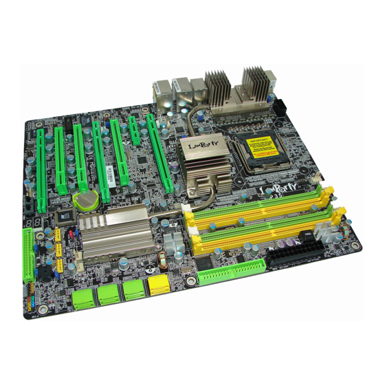
Hardware Installation Chapter 2 - Hardware Installation System Board Layout LP UT P35 Series... -
Page 28: Hardware Installation
Hardware Installation LP LT P35 Series Note: The illustrations on the following pages are based on the LP UT P35 system board. -
Page 29: System Memory
Hardware Installation Warning: Electrostatic discharge (ESD) can damage your system board, proces- sor, disk drives, add-in boards, and other components. Perform the upgrade instruction procedures described at an ESD workstation only. If such a station is not available, you can provide some ESD protec- tion by wearing an antistatic wrist strap and attaching it to a metal part of the system chassis. - Page 30 Hardware Installation The four DIMM sockets on the system board are divided into 2 channels: Channel A - DIMM 1 and DIMM 2 Channel B - DIMM 3 and DIMM 4 The system board supports the following memory interface. Single Channel (SC) Data will be accessed in chunks of 64 bits (8B) from the memory channels.
-
Page 31: Installing The Dim Module
Hardware Installation Installing the DIM Module Note: The system board used in the following illustrations may not resemble the actual board. These illustrations are for reference only. 1. Make sure the PC and all other peripheral devices connected to it has been powered down. 2. - Page 32 Hardware Installation 6. Grasping the module by its edges, position the module above the socket with the “notch” in the module aligned with the “key” on the socket. The keying mechanism ensures the module can be plugged into the socket in only one way. 7.
-
Page 33: Cpu
Hardware Installation Overview The system board is equipped with a surface mount LGA 775 socket. This socket is exclusively designed for installing a LGA 775 packaged Intel CPU. Important: 1. Before you proceed, make sure (1) the LGA775 1. Before you proceed, make sure (1) the LGA775 1. - Page 34 Hardware Installation Cover 4. The CPU socket comes with a cover that is attached with a remov- able protective cap. The Protective cap cap is used to protect the CPU socket against dust and harmful parti- Lever cles. Remove the protec- tive cap only when you are about to install the CPU.
- Page 35 Hardware Installation 8. Position the CPU above the socket. The gold mark on the CPU must align with pin 1 of the CPU socket. Important: Handle the CPU by its edges and avoid touch- ing the pins. Pin 1 of the socket Gold mark 9.
- Page 36 Hardware Installation 10. Once the CPU is in Cover place, move the cover down. 11. Push the lever down to lock the socket. The lever should hook onto the side tab to indicate that the CPU is com- pletely secured in the Lever socket.
- Page 37 Hardware Installation 2. Place the heat sink on Mounting hole top of the CPU. The 4 studs around the heat Mounting hole sink which are used to secure the heat sink onto the system board must match the 4 mounting holes around the socket.
-
Page 38: Transpiper Heat Sink
Hardware Installation Transpiper Heat Sink (LP UT P35 Series only) Due to space restrictions, the heat dissipating effect of a heat sink mounted directly at the place where the heat is produced is usually limited. To overcome this problem, the system board uses the heat pipe design. - Page 39 Hardware Installation The Transpiper heat sink is included in the package. Install the Transpiper either inside the chassis, anywhere along an available ex- pansion slot or externally - both of which provide effective cooling to the entire system. metal Transpiper Installing the Transpiper Inside the Chassis 1.
- Page 40 Hardware Installation 2. Insert the longer side of the 90 metal into the Transpiper. You can adjust its length later on before you fix the Transpiper in place. metal 3. Insert the nuts into the southbridge’s heat sink as shown. 4.
- Page 41 Hardware Installation 5. Coming from a side of Bracket the board, inser t the Transpiper under the metal plate. Adjust the Transpiper to an avail- Screws able expansion slot then tighten its screws. The right photo shows the Transpiper on the PCI 3 slot.
- Page 42 Hardware Installation Installing the Transpiper Outside the Chassis Before you proceed, make sure you have already installed the CPU. Refer to the “CPU” section in this chapter for installation instructions. 1. Place the copper plate on top of the CPU then secure it with the pro- vided screws.
- Page 43 Hardware Installation 4. Position the retention Bottom side module base at the of the board bottom of the system board then match and inser t the screws into the mounting holes around the CPU socket - from the bottom through the top of the Retention system board.
- Page 44 Hardware Installation 6. Apply a thin layer of thermal paste on top of the copper plate. Do not spread the paste all over the surface. When you later place the heat sink on top, the com- pound will disper se evenly.
- Page 45 Hardware Installation 9. Install the system board into the chassis. 10. Loosen the screws on the Transpiper. Screws 11. Insert the longer side of the 90 metal into the Transpiper. You can ad- just its length later on before you fix the Transpiper in place.
- Page 46 Hardware Installation 12. From the rear outside of the chassis, insert the shorter side of the 90 metal through the I/O shield so that it goes Location where under the metal plate the 90 metal is which you have installed inserted in step 2.
-
Page 47: Jumper Settings
Hardware Installation Jumper Settings Clear CMOS Data Clearing CMOS Data using JP2 1-2 On: Normal 2-3 On: (default) Clear CMOS Data If you encounter the following, a) CMOS data becomes corrupted. b) You forgot the supervisor or user password. c) You are unable to boot-up the computer system because the processor’s ratio/clock was incorrectly set in the BIOS. - Page 48 Hardware Installation 4. After powering-on the system, press <Del> to enter the main menu of the BIOS. 5. Select the Genie BIOS Setting submenu and press <Enter>. 6. Set the processor’s ratio/clock to its default setting or an appro- priate setting. Refer to the Genie BIOS Setting in chapter 3 for more information.
- Page 49 Hardware Installation ® Clearing CMOS Data using the EZ Clear Function ® EZ Clear bypasses the manual process of using a jumper to clear the CMOS by simply using the reset and power buttons. Important: ® EZ Clear is supported only if standby power is present in the system.
- Page 50 Hardware Installation PS/2 Power Select 1-2 On: 5V 2-3 On: (default) 5VSB JP7 is used to select the power of the PS/2 keyboard/mouse port. Selecting 5VSB will allow you to use the PS/2 keyboard or PS/2 mouse to wake up the system. BIOS Setting Configure the PS/2 keyboard/mouse wake up function in the Inte- grated Peripherals submenu (“Super IO Device”...
-
Page 51: Usb Power Select
Hardware Installation USB Power Select USB 6-11 (JP5) 2-3 On: 1-2 On: 5V (default) 5VSB USB 0-5 1-2 On: 5V 2-3 On: (JP6) 5VSB (default) JP5 and JP6 are used to select the power of the USB ports. Select- ing 5VSB will allow you to use the USB keyboard or USB mouse to wake up the system.. - Page 52 Hardware Installation Speaker On/Off Select Buzzer 1-2 On: 2-3 On: Speaker On Speaker Off (default) The system board is equipped with a buzzer which serves as the PC’s speaker. By default the buzzer is “on” allowing you to hear the system’s beep messages and warnings.
- Page 53 Hardware Installation Safe Boot 1-2 On: 2-3 On: Default Safe boot JP1 is used to safely reboot the system whenever the system hangs and you are unable to restart the system. 1. Power-off the system and unplug the power cord. 2.
-
Page 54: Secondary Rtc Reset
Hardware Installation Secondary RTC Reset JP12 1-2 On: Normal 2-3 On: (default) RTC reset When the RTC battery is removed, JP12 resets the manageability register bits in the RTC. Note: 1. The SRTCRST# input must always be high when all other RTC power planes are on. - Page 55 Hardware Installation CPU FSB Select JP14 JP15 JP13 By default, JP13 to JP15 are set to pins 1 and 2 On. This setting will allow the system to automatically run according to the CPU’s FSB. If you want to change the setting, please refer to the table below. By CPU FSB 1333 FSB 800...
-
Page 56: Rear Panel I/O Ports
Hardware Installation Rear Panel I/O Ports PS/2 LAN 1 LAN 2 Mouse 1394-0 USB 10-11 USB 6-7 PS/2 USB 8-9 LP UT P35 Series PS/2 LAN 1 LAN 2 Mouse 1394-0 USB 6-7 PS/2 USB 10-11 USB 8-9 LP LT P35 Series The rear panel I/O ports consist of the following: •... - Page 57 Hardware Installation PS/2 Mouse and PS/2 Keyboard Ports PS/2 Mouse PS/2 Keyboard The onboard PS/2 mouse (Green) and PS/2 keyboard (Purple) ports are both at location CN2 of the system board. The PS/2 mouse port uses IRQ12. If a mouse is not connected to this port, the system will reserve IRQ12 for other expansion cards.
- Page 58 Hardware Installation IEEE 1394 Ports 1394-0 1394-1 The onboard IEEE 1394 port is at location CN3 (IEEE 1394-0) of the system board. It is also equipped with an IEEE 1394 connector at location J8 (1394-1) for connecting an additional 1394 device. The 1394 port may come mounted on a card-edge bracket.
- Page 59 Hardware Installation USB (Universal Serial Bus) Ports USB 11 USB 10 USB 9 USB 8 USB 7 USB 6 USB 4-5 USB 0-1 USB 2-3 The system board supports 12 USB 2.0/1.1 ports. USB allows data exchange between your computer and a wide range of simultane- ously accessible external Plug and Play peripherals.
- Page 60 Hardware Installation Driver Installation You may need to install the proper drivers in your operating system to use the USB device. Refer to your operating system’s manual or documentation for more information. Refer to chapter 4 for more information about installing the USB 2.0 driver.
- Page 61 Hardware Installation RJ45 LAN Ports LAN 1 LAN 2 The onboard LAN ports are at locations CN4 (LAN 1) and CN6 (LAN 2) of the system board. LAN allows the system board to connect to a local area network by means of a network hub. Driver Installation Install the LAN driver.
-
Page 62: Bernstein Audio Module
Hardware Installation Bernstein Audio Module CD-in Line-in Line-out Front audio Mic-in Optical S/PDIF Center/ Subwoofer Rear R/L Side R/L Bernstein audio S/PDIF-out module connector S/PDIF-in Line-in Jack (Light Blue) This jack is used to connect any audio devices such as Hi-fi set, CD player, tape player, AM/FM radio tuner, synthesizer, etc. - Page 63 Hardware Installation Coaxial RCA S/PDIF-in and SPDIF-out Jacks These jacks are used to connect external audio output devices using coaxial S/PDIF cables. CD-in Connector The CD-in connector at location J2 is used to receive audio from a CD-ROM drive, TV tuner or MPEG card. Front Audio Connector The front audio connector at location J4 allows you to connect to the line-out and mic-in jacks that are at the front panel of your...
- Page 64 Hardware Installation Installing the Bernstein Audio Module 1. The Bernstein audio module connects to the system board by means of the provided audio cable. 2. Insert one end of the cable to J7 on the system board and the other end to J5 on the audio module. Bernstein audio module connector (J5)
- Page 65 Hardware Installation 3. The length of the audio cable provides the option and flexibility of installing the module on any available bracket slot at the rear of the system chassis. Remove the screw of the bracket where you want the audio module installed then remove the bracket. 4.
-
Page 66: Internal I/O Connectors
Hardware Installation I/O Connectors Floppy Disk Drive Connector The system board is equipped with a floppy disk drive connector that supports a standard floppy disk drive. To prevent improper floppy cable installation, the floppy disk header has a keying mecha- nism. -
Page 67: Serial Ata Connectors
Hardware Installation Serial ATA Connectors SATA 1-6 supported by Intel ICH9R SATA 7-8 supported by JMicron JMB363 SATA 7-8 SATA 1-2 SATA 3-4 SATA 5-6 • Intel ICH9R chip SATA speed up to 3Gb/s RAID 0, RAID 1, RAID 0+1 and RAID 5 •... -
Page 68: Ide Disk Drive Connector
Hardware Installation IDE Disk Drive Connector The system board is equipped with a shrouded PCI IDE header that will interface two Enhanced IDE (Integrated Drive Electronics) disk drives. To prevent improper IDE cable installation, the shrouded PCI IDE header has a keying mechanism. The 40-pin connector on the IDE cable can be placed into the header only if pin 1 of the connector is aligned with pin 1 of the header. - Page 69 Hardware Installation Adding a Second IDE Disk Drive When using two IDE drives, one must be set as the master and the other as the slave. Follow the instructions provided by the drive manufacturer for setting the jumpers and/or switches on the drives. The system board suppor ts Enhanced IDE or ATA-2, ATA/33, ATA/66 or ATA/100 hard drives.
- Page 70 Hardware Installation Serial (COM) Port The 9-pin connector at location J4 is for connecting an external serial port. The serial port cable is an optional item and must be pur- chased separately. Insert the connector that is attached to the serial port cable to J4 then install the serial port bracket to an available bracket slot at the rear of the system chassis.
- Page 71 Hardware Installation IrDA and CIR Connectors IRRX Ground N. C. IRTX IrDA CIRTX 5VSB Ground N. C. CIRRX Connect the cable connector from your IrDA module to the IrDA connector (J5) or CIR connector (J14). Note: The sequence of the pin functions on some IrDA/CIR cable may be reversed from the pin function defined on the system board.
-
Page 72: Cooling Fan Connectors
Hardware Installation Cooling Fan Connectors Ground Power Sense Speed Control CPU fan Power Ground N. C. N. C. Power Ground NB fan 3rd fan Power Ground N. C. System fan Power Ground N. C. Ground N. C. Power 2nd fan 1st fan Connect the CPU fan’s cable connector to the CPU fan connector (J31) on the system board. - Page 73 Hardware Installation LEDs DRAM Power LED Standby Diagnostic Power LED DRAM Power LED This LED will light when the system’s power is on. Standby Power LED This LED will light when the system is in the standby mode. Diagnostic LED The Diagnostic LED displays POST codes.
-
Page 74: Power Connectors
Hardware Installation Power Connectors Use a power supply that complies with the ATX12V Power Supply Design Guide Version 1.1. An ATX12V power supply unit has a standard 24-pin ATX main power connector that must be inserted onto CN10. 1 2 2 4 +3.3VDC +12VDC +5VDC... - Page 75 Hardware Installation The power connectors from the power supply unit are designed to fit the 24-pin and 8-pin connectors in only one orientation. Make sure to find the proper orientation before plugging the connectors. The FDD-type power connectors are additional power connector.s If you are using more than one graphics cards, we recommend that you plug a power cable from your power supply unit onto the 5V/12V power connectors at locations J1 and/or J15.
- Page 76 Hardware Installation Restarting the PC Normally, you can power-off the PC by: 1. Pressing the power button at the front panel of the chassis. 2. Pressing the power switch that is on the system board (note: not all system boards come with this switch). If for some reasons you need to totally cut off the power supplied to the PC, switch off the power supply or unplug the power cord.
-
Page 77: Front Panel Connectors
Hardware Installation Front Panel Connectors RESET SPEAKER HD-LED PWR-LED ATX-SW HD-LED: Primary/Secondary IDE LED This LED will light when the hard drive is being accessed. RESET: Reset Switch This switch allows you to reboot without having to power off the system thus prolonging the life of the power supply or system. - Page 78 Hardware Installation PWR-LED: Power/Standby LED When the system’s power is on, this LED will light. When the system is in the S1 (POS - Power On Suspend) or S3 (STR - Suspend To RAM) state, it will blink every second. Note: If a system did not boot-up and the Power/Standby LED did not light after it was powered-on, it may indicate that the CPU...
- Page 79 Hardware Installation EZ Touch Switches Reset Power The presence of the power switch and reset switch on the system board are user-friendly especially to DIY users. They provide conven- ience in powering on and/or resetting the system while fine tuning the system board before it is installed into the system chassis.
- Page 80 Hardware Installation PCI Express Slots PCI Express x16 PCI Express x1 PCI Express x16 PCI Express x16 PCI Express x16 Install PCI Express x16 graphics card, that comply to the PCI Ex- press specifications, into the PCI Express x16 slot. To install a graph- ics card into the x16 slot, align the graphics card above the slot then press it down firmly until it is completely seated in the slot.
- Page 81 Hardware Installation Battery The lithium ion battery powers the real-time clock and CMOS memory. It is an auxiliary source of power when the main power is shut off. Safety Measures • Danger of explosion if battery incorrectly replaced. • Replace only with the same or equivalent type recommend by the manufacturer.
-
Page 82: Chapter 3 - Bios Setup
BIOS Setup Chapter 3 - BIOS Setup Award BIOS Setup Utility The Basic Input/Output System (BIOS) is a program that takes care of the basic level of communication between the processor and pe- ripherals. In addition, the BIOS also contains codes for various ad- vanced features found in this system board. -
Page 83: Standard Cmos Features
BIOS Setup Standard CMOS Features Use the arrow keys to highlight “Standard CMOS Features” then press <Enter>. A screen similar to the one below will appear. Phoenix - AwardBIOS CMOS Setup Utility Standard CMOS Features Date <mm:dd:yy> Thu, Jun 28 2007 Item Help Time <hh:mm:ss>... -
Page 84: Bios Setup
BIOS Setup IDE Channel 0 Master to IDE Channel 3 Master To configure the IDE drives, move the cursor to a field then press <Enter>. The following screen will appear. Phoenix - AwardBIOS CMOS Setup Utility IDE Channel 0 Master Press Enter IDE HDD Auto-Detection Item Help... - Page 85 BIOS Setup Capacity Displays the approximate capacity of the disk drive. Usually the size is slightly greater than the size of a formatted disk given by a disk checking program. Cylinder This field displays the number of cylinders. Head This field displays the number of read/write heads. Precomp This field displays the number of cylinders at which to change the write timing.
- Page 86 BIOS Setup Video This field selects the type of video adapter used for the primary system monitor. Although secondary monitors are supported, you do not have to select the type. The default setting is EGA/VGA. EGA/VGA Enhanced Graphics Adapter/Video Graphics Array. For EGA, VGA, SVGA and PGA monitor adapters.
- Page 87 BIOS Setup Extended Memory Displays the amount of extended memory detected during boot-up. Total Memory Displays the total memory available in the system.
-
Page 88: Advanced Bios Features
BIOS Setup Advanced BIOS Features The Advanced BIOS Features allows you to configure your system for basic operation. Some entries are defaults required by the system board, while others, if enabled, will improve the performance of your system or let you set some features according to your preference. Phoenix - AwardBIOS CMOS Setup Utility Advanced BIOS Features Press Enter... - Page 89 BIOS Setup Hard Disk Boot Priority This field is used to select the boot sequence of the hard drives. Move the cursor to this field then press <Enter>. Use the Up or Down arrow keys to select a device then press <+> to move it up or <->...
- Page 90 BIOS Setup ® Hyper-Threading Technology (for Intel processor with Hyper- Threading Technology only) ® This field is used to enable the functionality of an Intel processor that supports Hyper-Threading Technology and will appear only when using this processor. Quick Power On Self Test This field speeds up Power On Self Test (POST) whenever the sys- tem is powered on.
- Page 91 BIOS Setup Security Option This field determines when the system will prompt for the password- everytime the system boots or only when you enter the BIOS setup. Set the password in the Set Supervisor/User Password submenu. System The system will not boot and access to Setup will be denied unless the correct password is entered at the prompt.
-
Page 92: Advanced Chipset Features
BIOS Setup Advanced Chipset Features Phoenix - AwardBIOS CMOS Setup Utility Advanced Chipset Features Memory Hole At 15M-16M Disabled Item Help PCI-E Compliancy Mode Disabled Menu Level ↑↓→← : Move Enter: Select +/-/PU/PD: Value F10: Save ESC: Exit F1: General Help F5: Previous Values F6: Fail-Safe Defaults F7: Optimized Defaults... -
Page 93: Integrated Peripherals
BIOS Setup Integrated Peripherals Phoenix - AwardBIOS CMOS Setup Utility Integrated Peripherals Item Help OnChip IDE Device Press Enter Super IO Device Press Enter Menu Level USB Device Setting Press Enter ↑↓→← : Move Enter: Select +/-/PU/PD: Value F10: Save ESC: Exit F1: General Help F5: Previous Values... - Page 94 BIOS Setup SATA Mode This field is used to configure the SATA devices supported by the Intel ICH9R. This option configures the Serial ATA drives as Parallel ATA storage devices. RAID This option allows you to create RAID or Intel Matrix Storage configuration on Serial ATA devices.
-
Page 95: Super Io Device
BIOS Setup Super IO Device Phoenix - AwardBIOS CMOS Setup Utility Super IO Device Disabled Power On By Mouse Item Help Power On By Keyboard Button Only Menu Level x Power On By Button Enabled Enter x KB Power On Password x Hot Key Power On Ctrl+F1 Onboard FDC Controller... - Page 96 BIOS Setup Power On By Button To use the power button to power on the system, set this field to Enabled. KB Power On Password Move the cursor to this field and press <Enter>. Enter your pass- word. You can enter up to 5 characters. Type in exactly the same password to confirm, then press <Enter>.
- Page 97 BIOS Setup IR Mode Select This field is used to select the type of IrDA standard supported by your IrDA device. For better transmission of data, your IrDA periph- eral device must be within a 30 angle and within a distance of 1 meter.
-
Page 98: Usb Device Setting
BIOS Setup USB Device Setting Phoenix - AwardBIOS CMOS Setup Utility USB Device Setting USB 1.0 Controller Enabled Item Help USB 2.0 Controller Enabled Menu Level USB Operation Mode High Speed USB Keyboard Function Enabled [Enable] or [Disable] USB Mouse Function Enabled Universal Host USB Storage Function... - Page 99 BIOS Setup USB Keyboard Function Due to the limited space of the BIOS ROM, the support for legacy USB keyboard (in DOS mode) is by default set to Disabled. With more BIOS ROM space available, it will be able to support more advanced features as well as provide compatibility to a wide variety of peripheral devices.
-
Page 100: Power Management Setup
BIOS Setup Power Management Setup The Power Management Setup allows you to configure your system to most effectively save energy. Phoenix - AwardBIOS CMOS Setup Utility Power Management Setup ACPI Suspend Type S3(STR) Item Help Run VGABIOS if S3 Resume Auto Menu Level Instant-Off... - Page 101 BIOS Setup Soft-Off by PWR-BTTN This field allows you to select the method of powering off your system. Delay 4 Sec. Regardless of whether the Power Management func- tion is enabled or disabled, if the power button is pushed and released in less than 4 sec, the system enters the Suspend mode.
- Page 102 BIOS Setup Resume By Alarm Enabled When Enabled, you can set the time you would like the Soft Power Down (Soft-Off) PC to power-on in the “Time (dd:hh:mm) of Alarm” field. However, if the system is being accessed by incoming calls or the network prior to the time set in the field, the system will give priority to the incoming calls or network.
-
Page 103: Init Display First
BIOS Setup PnP/PCI Configurations This section describes configuring the PCI bus system. It covers some very technical items and it is strongly recommended that only experienced users should make any changes to the default settings. Phoenix - AwardBIOS CMOS Setup Utility PnP/PCI Configurations Init Display First PCI Slot... -
Page 104: Resources Controlled By
BIOS Setup Resources Controlled By The Award Plug and Play BIOS has the capability to automatically configure all of the boot and Plug and Play compatible devices. Auto(ESCD) The system will automatically detect the settings for you. Manual Choose the specific IRQ in the “IRQ Resources” field. - Page 105 BIOS Setup PCI Latency Timer (per 8CLK) This feature is used to select the length of time each PCI device will control the bus before another takes over. The larger the value, the longer the PCI device can retain control of the bus. Since each ac- cess to the bus comes with an initial delay before any transaction can be made, low values for the PCI Latency Timer will reduce the effectiveness of the PCI bandwidth while higher values will improve it.
-
Page 106: Pc Health Status
BIOS Setup PC Health Status Phoenix - AwardBIOS CMOS Setup Utility PC Health Status Shutdown Temperature C/185 Item Help >50 CPUFan Fully On if CPUTemp Menu Level <25 CPUFan Turn OFF if CPUTemp CHSFan Fully On if CHSTemp >35 CHSFan Turn OFF if CHSTemp <25 >55 NB Fan Fully On if NB Temp... - Page 107 BIOS Setup CPUFan Turn Off If CPUTemp This field is used to select the CPU’s temperature at which the CPU fan will rotate at a start speed which is the slowest speed. Note: 1. If the CPU temperature runs between the highest (set in the “CPUFan Fully On If CPUTemp”...
- Page 108 BIOS Setup NB Fan Turn Off If NB Temp This field is used to select the Nor thbridge chip’s temperature that would allow the chip’s fan to rotate at a start speed which is the slowest speed. Note: If the north bridge chip’s temperature runs between the high- est (set in the “NB Fan Fully On If NB Temp”...
-
Page 109: Genie Bios Setting
BIOS Setup Genie BIOS Setting Phoenix - AwardBIOS CMOS Setup Utility Genie BIOS Setting Item Help CPU Feature Press Enter DRAM Timing Press Enter Menu Level CPU Clock Ratio Unlock Disabled x CPU Clock Ratio CPU Clock 266MHz Boot Up Clock Auto DRAM Speed Auto... - Page 110 BIOS Setup Boot Up Clock This field is used to select the boot up clock. DRAM Speed This field is used to select the clock speed of the DIMM. Target DRAM Speed This field will show the current target DRAM speed. PCIE Clock This field is used to select the bus clock of the PCI Express.
-
Page 111: Cpu Feature
BIOS Setup CPU Feature Move the cursor to this field and press <Enter>, the following screen will appear: Phoenix - AwardBIOS CMOS Setup Utility CPU Feature Thermal Management Control Enabled Item Help Thermal Monitor 1 Thermal Management Menu Level TM2 Bus Ratio TM2 Bus VID 0.8375 ↑... - Page 112 BIOS Setup TM2 Bus VID This field is used to select the voltage of the throttled performance state that will be initiated when the on-die sensor turns from cool to hot. PPM Mode The options are Native Mode and SMM mode. Limit CPUID MaxVal The CPUID instruction of some newer CPUs will return a value greater than 3.
-
Page 113: Dram Timing
BIOS Setup DRAM Timing Move the cursor to this field and press <Enter>. The following screen will appear. Phoenix - AwardBIOS CMOS Setup Utility DRAM Timing Item Help DLL Timing Press Enter Enhanced Data Transmitting Auto Menu Level Auto Enhanced Addressing Auto Channel 1 CLK Fine Delay Channel 2 CLK Fine Delay... - Page 114 BIOS Setup CAS Latency Time (tCL) This field is used to select the clock cycle of the CAS latency time. The option selected specifies the timing delay before SDRAM starts a read command after receiving it. RAS# to CAS# Delay (tRCD) This field is used to select the RAS# to CAS# delay time when reading and writing to the same bank.
- Page 115 BIOS Setup Read to Write Delay (tRDWR) This field is used to select the read to write delay time. Although this is not a DRAM specified timing parameter, it is related to the routing latencies on the clock forwarded bus. This is measured from the first address bus slot which is not associated with part of the read burst.
- Page 116 BIOS Setup DLL Timing Move the cursor to this field and press <Enter>. The following screen will appear. Phoenix - AwardBIOS CMOS Setup Utility DLL Timing Item Help DLL Async Mode Auto WRIO Master DLL Auto Menu Level Auto DQS Master DLL Auto RCVEN Master DLL RCVEN Slave DLL Delay...
- Page 117 BIOS Setup DLL Tap Adjust The options are Auto, +1 to +7. DLL Pi Adjust The options are Auto, +1 to +7.
- Page 118 BIOS Setup Voltage Setting Move the cursor to this field and press <Enter>. The following screen will appear. Phoenix - AwardBIOS CMOS Setup Utility Voltage Setting Item Help CPU VID Control Auto CPU VID Special Add Auto Menu Level 2.01V DRAM Voltage Control 1.05V SB 1.05V Voltage...
- Page 119 BIOS Setup SB 1.05V Voltage The options are 1.05V, 1.133V, 1.217V and 1.3V. SB Core Voltage The options are 1.5V, 1.6V, 1.7V and 1.8V. NB Core Voltage The options are 1.25V to 1.55V. HT Link Voltage The options are 1.20V to 1.50V. GTL REF Voltage Control The options are Enabled and Disabled.
-
Page 120: Cmos Reloaded
BIOS Setup CMOS Reloaded The CMOS Reloaded submenu allows you to save different configu- rations and when needed, allows you to conveniently restore one of these previously saved configurations. Highlight CMOS Reloaded in the main menu then press <Enter>. Phoenix - AwardBIOS CMOS Setup Utility CMOS Reloaded Item Help Auto Save Bootable Setting... - Page 121 BIOS Setup Auto Save Bootable Setting This field is used to automatically save the last bootable setting from CMOS to an area in the SEEPROM referred to as the backup bank. To use this function: 1. Set this field to Enabled. 2.
- Page 122 BIOS Setup Saving, Loading and Naming BIOS Settings For overclockers who require different sets of settings for various system environments or operating systems, CMOS Reloaded allows you to save, load and name up to four sets of BIOS settings - in the “User Defined Setting Bank #1”...
- Page 123 BIOS Setup Load from this Bank To load the setting saved in the bank, move the cursor to “Load from this Bank” then press <Enter>. The setting in this bank will replace the current setting. Make sure to save before you exit the BIOS setup utility by selecting “Y”...
-
Page 124: Load Optimized Defaults
BIOS Setup Load Optimized Defaults The “Load Optimized Defaults” option loads optimized settings from the BIOS ROM. Use the default values as standard values for your system. Highlight this option in the main menu and press <Enter>. Phoenix - AwardBIOS CMOS Setup Utility Standard CMOS Features Genie BIOS Setting Advanced BIOS Features... -
Page 125: Set Supervisor Password
BIOS Setup Set Supervisor Password If you want to protect your system and setup from unauthorized entry, set a supervisor’s password with the “System” option selected in the Advanced BIOS Features. If you want to protect access to setup only, but not your system, set a supervisor’s password with the “Setup”... -
Page 126: Set User Password
BIOS Setup Set User Password If you want another user to have access only to your system but not to setup, set a user’s password with the “System” option se- lected in the Advanced BIOS Features. If you want a user to enter a password when trying to access setup, set a user’s password with the “Setup”... -
Page 127: Save & Exit Setup
BIOS Setup Save & Exit Setup When all the changes have been made, highlight “Save & Exit Setup” and press <Enter>. Phoenix - AwardBIOS CMOS Setup Utility Standard CMOS Features Genie BIOS Setting Advanced BIOS Features CMOS Reloaded Advanced Chipset Features Load Optimized Defaults Integrated Peripherals Set Supervisor Password... -
Page 128: Exit Without Saving
BIOS Setup Exit Without Saving When you do not want to save the changes you have made, high- light “Exit Without Saving” and press <Enter>. Phoenix - AwardBIOS CMOS Setup Utility Standard CMOS Features Genie BIOS Setting Advanced BIOS Features CMOS Reloaded Advanced Chipset Features Load Optimized Defaults... -
Page 129: Raid Bios
BIOS Setup RAID BIOS Intel RAID BIOS The Intel RAID BIOS utility is used to configure and manage RAID on Serial ATA drives connected to SATA 1 to SATA 6. When the system powers-up and all drives have been detected, the Intel RAID BIOS status message screen will appear. -
Page 130: Updating The Bios
Updating the BIOS To update the BIOS, you will need the new BIOS file and a flash utility, AWDFLASH.EXE. You can download them from DFI’s web site or contact technical support or your sales representative. 1. Save the new BIOS file along with the flash utility AWDFLASH.EXE to a floppy disk. - Page 131 BIOS Setup 6. The following will appear. Do You Want to Save BIOS (Y/N) This question refers to the current existing BIOS in your system. We recommend that you save the current BIOS and its flash utility; just in case you need to reinstall the BIOS. To save the current BIOS, press <Y>...
-
Page 132: Chapter 4 - Supported Software
Supported Software Chapter 4 - Supported Software Drivers, Utilities and Software Applications The CD that came with the system board contains drivers, utilities and software applications required to enhance the performance of the system board. Insert the CD into a CD-ROM drive. The autorun screen will appear. If after inserting the CD, "Autorun"... -
Page 133: Supported Software
Supported Software Intel Chipset Device Software On the left side of the autorun screen, click the “CHIPSET” icon. 1. Click “Intel(R) Chipset Device Software” on the main menu. 2. Setup is now ready to install the utility. Click Next. - Page 134 Supported Software 3. Read the license agree- ment then click Yes. 4. Go through the readme document for system requirements and instal- lation tips then click Next. 5. Setup is now installing the driver. Click Next to continue.
- Page 135 Supported Software 6. Click “Yes, I want to restar t this computer now” then click Finish. Restar ting the system will allow the new software installation to take effect.
- Page 136 Supported Software Microsoft .NET Framework On the left side of the autorun screen, click the “GRAPHICS” icon. 1. Click “Microsoft .NET Framework” on the main menu. 2. Setup is now ready to install the utility. Click Next.
- Page 137 Supported Software 3. Read license agreement then click “I accept the terms of the License Agreement. ” . Click Install. 4. Setup is now installing the driver.
- Page 138 Supported Software 5. Click Finish. Reboot the system for the new software installation to take effect. Graphics Drivers The CD provides both ATI Radeon driver and nVidia GForce 8 series driver. Install the driver according to the graphics card that you are using. For ATI Radeon graphics card, select ATI Radeon Driver.
-
Page 139: Realtek Audio Drivers
Supported Software Realtek Audio Drivers On the left side of the autorun screen, click the “AUDIO” icon. 1. Click “Realtek Audio Drivers” on the main menu. 2. Setup is now ready to install the audio driver. Click Next. 3. Setup currently configuring the new driver’s installation. - Page 140 Supported Software 4. Setup is now processing the settings. 5. Select the desired option then click Next. 6. Click “Yes, I want to restar t my computer now” then click Finish. Restar ting the system will allow the new software installation to take effect.
- Page 141 Supported Software Marvell LAN Drivers - 32bits On the left side of the autorun screen, click the “NETWORK” icon. 1. Click “Mar vell LAN Drivers - 32bits” on the main menu. 2. Setup is now ready to install the driver. Click Next.
- Page 142 Supported Software 4. Click Install to begin the installation. 5. After completing installa- tion, click Finish to exit setup. Reboot your system for software installation to take effect.
- Page 143 Supported Software Marvell Teaming Utility On the left side of the autorun screen, click the “NETWORK” icon. 1. Click “Mar vell Teaming Utility” on the main menu. 2. Setup is now preparing the wizard. 3. Setup is now ready to install the utility.
- Page 144 Supported Software 4. Read license agreement, click “I accept the terms in the license agreement.” then click Next. 5. Go through the readme document for system requirements and installa- tion tips then click Next. 6. Click Install to begin the installation.
- Page 145 Supported Software 7. Click Finish.
- Page 146 Supported Software ITE Smart Guardian The ITE Smart Guardian utility is capable of monitoring the system’s tem- perature, fan speed, voltage, etc. and allows you to manually set a range (Highest and Lowest Limit) to the items being monitored. If the settings/ values are over or under the set range, a warning message will pop-up.
- Page 147 Supported Software 3. Fill in the necessar y information then click Next.. 4. Click Next to install or click Browse to select another folder. 5. Select an option in accordance to the system that you are using then click Next.
- Page 148 Supported Software 6. After completing installa- tion, click Finish to exit setup. Restarting the system will allow the utility to take effect.
-
Page 149: Installation Notes
Supported Software USB 2.0 Drivers ® Windows ® If your Windows XP CD already includes Service Pack 1, the USB 2.0 driver will automatically install when you install the operating system. If the CD does not include Service Pack 1, it is available for download at Microsoft’s Windows Update website. -
Page 150: Chapter 5 - Raid
RAID Chapter 5 - RAID The Intel ICH9R chip alows configuring RAID on Serial ATA drives connected to SATA 1 to SATA 6. It supports RAID 0, RAID 1, RAID 0+1 and RAID 5. The JMicron JMB363 chip allows configuring RAID on another 2 Se- rial ATA drives (connected to SATA 7 and SATA 8). - Page 151 RAID Settings To enable the RAID function, the following settings are required. 1. Connect the Serial ATA drives. 2. Configure Serial ATA in the Award BIOS. 3. Configure RAID in the RAID BIOS. 4. Install the RAID driver during OS installation. 5.
- Page 152 RAID Step 2: Configure Serial ATA in the Award BIOS 1. Power-on the system then press <Del> to enter the main menu of the Award BIOS. 2. Select the Integrated Peripherals submenu - OnChip IDE Device section of the BIOS. 3.
- Page 153 RAID Step 3: Configure RAID in the RAID BIOS Configure RAID in the Intel RAID BIOS When the system powers-up and all drives have been detected, the Intel RAID BIOS status message screen will appear. Press the <Ctrl> and <I> keys simultaneously to enter the utility. The utility allows you to build a RAID system on Serial ATA drives.
- Page 154 RAID You have successfully installed the driver. However you must continue installing the OS. Leave the floppy disk in the floppy drive until the system reboots itself because Windows setup will need to copy the files again from the floppy disk to the Windows installation folders. After Windows setup has copied these files again, remove the floppy diskette so that Windows setup can reboot as needed.
- Page 155 RAID Step 5: Install the Intel Matrix Storage Manager The Intel Matrix Storage Manager can be installed from within Windows. It allows RAID volume management (create, delete, migrate) from within the operating system. It will also display useful SATA device and RAID volume information.
- Page 156 RAID 5. Read warning carefully then click Next. 6. Read license agreement then click Yes. 7. Go through the readme document view system requirements and installation information then click Next. 8. Follow the remainder of the steps listed on the screen; clicking “next” each time you finish a step.
- Page 157 RAID Step 6: Install the JMB36X Driver On the left side of the autorun screen, click the “RAID” icon. 1. Click “JMB36X Drivers” on the main menu. 2. Setup is now ready to install the driver. Click Next. 3. Click Install to begin the installation.
- Page 158 RAID 4. Setup is now installing the driver. 5. Follow the remainder of the steps listed on the screen; clicking “next” each time you finish a step. 6. Click “Yes, I want to restar t my computer now” then click Finish. Restarting the system will allow the new software installation to take effect.
-
Page 159: Appendix A - Enabling Hyper-Threading Technology
Enabling Hyper-Threading Technology Appendix A - Enabling Hyper-Threading Technology Enabling Hyper-Threading Technology To enable the functionality of the Hyper-Threading Technology, please follow the requirements and steps below. Basically, the following ® ® presumes that you have already installed an Intel Pentium Processor with Hyper-Threading Technology. - Page 160 Enabling Hyper-Threading Technology Click the General tab. The processor shown under Computer should resemble the one shown below. Now click the Hardware tab then click Device Manager. The items shown under Computer and Processors should resemble the ones shown below.
- Page 161 Enabling Hyper-Threading Technology Lastly, press the <Ctr l> <Alt> and <Del> keys simultaneously. The Windows Task Manager dialog box will appear. Click the Performance tab. The diagram under CPU Usage History should resemble the one shown below.
-
Page 162: Appendix B - System Error Message
System Error Message Appendix B - System Error Message When the BIOS encounters an error that requires the user to cor- rect something, either a beep code will sound or a message will be displayed in a box in the middle of the screen and the message, PRESS F1 TO CONTINUE, CTRL-ALT-ESC or DEL TO ENTER SETUP, will be shown in the information box at the bottom. - Page 163 System Error Message Hard Disk(s) fail (80) HDD reset failed. Hard Disk(s) fail (40) HDD controller diagnostics failed. Hard Disk(s) fail (20) HDD initialization error. Hard Disk(s) fail (10) Unable to recalibrate fixed disk. Hard Disk(s) fail (08) Sector Verify failed. Keyboard is locked out - Unlock the key The BIOS detects that the keyboard is locked.
-
Page 164: Appendix C - Troubleshooting
Troubleshooting Appendix C - Troubleshooting Troubleshooting Checklist This chapter of the manual is designed to help you with problems that you may encounter with your personal computer. To efficiently troubleshoot your system, treat each problem individually. This is to ensure an accurate diagnosis of the problem in case a problem has multiple causes. -
Page 165: Troubleshooting
Troubleshooting The picture seems to be constantly moving. 1. The monitor has lost its vertical sync. Adjust the monitor’s vertical sync. 2. Move away any objects, such as another monitor or fan, that may be creating a magnetic field around the display. 3. -
Page 166: Hard Drive
Troubleshooting Hard Drive Hard disk failure. 1. Make sure the correct drive type for the hard disk drive has been entered in the BIOS. 2. If the system is configured with two hard drives, make sure the bootable (first) hard drive is configured as Master and the sec- ond hard drive is configured as Slave. - Page 167 Troubleshooting 3. Verify that the attached serial device works by attaching it to a serial port that is working and configured correctly. If the serial device does not work, either the cable or the serial device has a problem. If the serial device works, the problem may be due to the onboard I/O or the address setting.