Table of Contents
Advertisement
Quick Links
USER'S MANUAL
- OPERATION -
Before operation, be sure to read this manual and obtain
full knowledge about this device through training.
Keep this manual safely in a specified place.
WARNING
TOKYO SEIMITSU CO., LTD.
Document No.
: FT32000-R001-E0
Date Issued
: 2010-05-26
FULLY AUTOMATIC
PROBER
UF200R
UF190R
Advertisement
Table of Contents

Summary of Contents for ACCRETECH UF200R
- Page 1 Date Issued : 2010-05-26 USER’S MANUAL FULLY AUTOMATIC - OPERATION - PROBER UF200R UF190R WARNING Before operation, be sure to read this manual and obtain full knowledge about this device through training. Keep this manual safely in a specified place.
- Page 2 PREFACE This User’s Manual for Operation explains the operation procedures for Fully Automatic Prober UF200R running on System Software Ver. S5.0U-P2. In addition to standard functions, this manual also covers common optional functions (either with or without the “Optional” note). For this reason, it should be noted that some of the descriptions in this manual may not apply to your particular system, depending on its configuration.
- Page 3 When working with the head stage or the chuck access door open, contact with the cold chuck may result in frostbite. • Do not touch the cold chuck when manually handling wafers or performing maintenance on the cold chuck. CAUTION • When relocating or disassembling the system, contact ACCRETECH. Failure to do so may void warranty.
- Page 4 ACCRETECH will provide any references necessary for the repair, but the cost shall be borne by the customer. ■ Scope of warranty ACCRETECH will not be liable for any damage or problem caused by any of the following. ・ Natural disasters. ・ Modifications made to the system without approval from ACCRETECH.
- Page 5 ACCRETECH or its suppliers, the system may malfunction or be hindered in performance. ACCRETECH will not be liable for damages resulting from the use of such components and parts. Furthermore, even if the components and parts were acquired from ACCRETECH or its suppliers, ACCRETECH will not be liable for damages caused by defects of such components and parts.
-
Page 6: Table Of Contents
Contents Contents 1 Operation Points and Startup 1.1 Appearance....................1-2 1.2 EMO and POWER Switches..............1-3 1.3 Display/Touch Panel Unit.................1-4 1.4 Head Stage ....................1-5 1.5 Storage Media...................1-6 1.6 Internal Printer (Optional) ................1-7 1.7 Loader Unit ....................1-8 1.8 Prober Startup ..................1-9 2 Lot Processing 2.1 Screen Display and Operations Prior to Starting Lot Processing ..2-2 2.1.1 Switching the display with the <Screen Change >button .... - Page 7 Contents 4 Wafer Mapping & Die Sampling 4.1 Operation Flow Chart ................4-2 4.2 Test Die Area Setting................4-3 4.2.1 Setting the test die area ................. 4-5 4.3 Reference Die Setting ................4-6 4.3.1 Target Sensing..................4-8 4.3.2 Difference between TEG and corner targets ........4-10 4.3.3 Setting the reference die..............
- Page 8 Contents 6.14 Make User File ..................6-8 6.15 System Reset....................6-9 7 APPENDIX Prober Status Display...
-
Page 9: Operation Points And Startup
1 Operation Points and Startup Appearance .................1-2 EMO and POWER Switches ..........1-3 Display/Touch Panel Unit ...........1-4 Head Stage ................1-5 Storage Media ..............1-6 1.5.1 Floppy Disk Drive (FDD)..............1-6 1.5.2 USB terminal ..................1-6 Internal Printer (Optional) ..........1-7 Loader Unit ................1-8 Prober Startup ..............1-9... - Page 10 Operation Points and Startup This chapter outlines the operation for the following operation points. The startup procedure from power-up to staring of operation is also explained. Operation points for UF200R/UF190R: 1) EMO (emergency stop) and POWER switches 2) Loader unit...
-
Page 11: Appearance
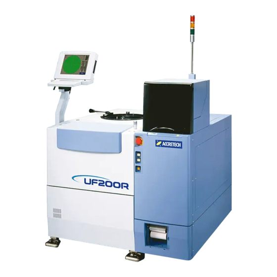
1 Operation Points and Startup 1.1 Appearance The external appearance of a standard specification UF200R system is shown below. Head stage Loader Display / Touch panel Storage media EMO switch POWER switches Internal printer (optional) -
Page 12: Emo And Power Switches
1 Operation Points and Startup 1.2 EMO and POWER Switches The EMO (emergency stop) and POWER switches are located on the right-hand side of the prober’s front panel. If an abnormality is observed during the operation of the loader, the chuck or the optional HF test head manipulator, press the EMO switch. -
Page 13: Display/Touch Panel Unit
1 Operation Points and Startup 1.3 Display/Touch Panel Unit The vertical and horizontal angles of the display/touch panel unit can be adjusted by loosening the clamp knob on the support joint. Clamp knob Display/Touch Panel (Screen) The screen displays information such as the prober status and control parameters. -
Page 14: Head Stage
1 Operation Points and Startup Head Stage The head stage on the top panel of the prober main body is used to attach the probe card. It is also used to support the test head for the tester. Clamp bolts Opening/closing the head stage 1) Check that there is no obstacle above and within the operation range of the head stage. -
Page 15: Storage Media
1 Operation Points and Startup 1.5 Storage Media UF200R is equipped with a USB terminal, both located at the bottom-right of the front panel. For normal prober operations, it is not necessary to use a USB terminal, as the device data (control parameter) can be written to the internal hard disk drive. -
Page 16: Internal Printer (Optional)
1 Operation Points and Startup 1.6 Internal Printer (Optional) An internal printer , which is an option, is installed on the lower left part of the Prober front. The print head is in the upper portion and the paper roll holder is in the center. You can feed printing paper by pushing FEED button. -
Page 17: Loader Unit
1.7 Loader Unit The cassette elevator in the loader unit supports 5-, 6- and 8-inch cassettes. In UF200R, processing of new cassettes and locking/unlocking of the inspection tray are performed with buttons on the display/touch panel. Touch the “NEW CST” button to process new cassettes, and the “Lock/Unlock” button to lock/unlock the inspection tray. -
Page 18: Prober Startup
1 Operation Points and Startup 1.8 Prober Startup “Startup” refers to the procedures from power-up to the completion of prober initialization. When the POWER ON switch is pressed and lit, the initialization screen (shown on left) is displayed. The “Operation mode” can be set to [Operator], [Engineer], [Manager] or [System], depending on the nature of the prober operation and on the skill level of the user. -
Page 19: Lot Processing
2 Lot Processing Screen Display and Operations Prior to Starting Lot Processing ..................2-2 2.1.1 Switching the display with the <Screen Change> button ...2-3 2.1.2 Operation settings ................2-4 Device Data Switching............2-5 2.2.1 Saving/deleting device data............2-7 Probe Card Replacement ...........2-8 Wafer Alignment..............2-11 2.4.1 Manual registration of models .............2-13 2.4.2. - Page 20 2 Lot Processing 2 Lot Processing This chapter explains the following procedures for the preparation and starting of wafer lot processing, which takes place after the completion of prober startup. 1) Screen display and operations prior to starting lot processing 2) Switching of device data 3) Replacement and management of prober cards 4) Wafer alignment...
-
Page 21: Screen Display And Operations Prior To Starting Lot Processing
2 Lot Processing 2.1 Screen Display and Operations Prior to Starting Lot Processing The Prober Status screen is displayed upon completion of initialization. Device data Information Lot number display area Operation set information display area <Lot Settings> button: Touch to display the lot setting screen. <Device Parameter Change>... -
Page 22: Switching The Display With The
2 Lot Processing 2.1.1 Switching the display with the <Screen Change> button Prober Status screen Touch the <Slot Information> button on the Prober Status screen to display the Lot Information screen, shown below. Lot Information screen When a cassette is set into the loader and the NEW CST switch is touched, wafer sensing is performed against the slots in the cassette, and the results are displayed for each slot as either “Unprocessed”...Button -
Page 23: Operation Settings
2 Lot Processing 2.1.2 Operation settings On the Prober Status or Lot Information/Loader Status screen before starting the lot processing, touch the <Operation Settings> button to display the [Operation Settings] screen (second screen shown on left). Before Starting Lot Processing In principle, operation settings apply only to the next wafer to be processed, unlike Device parameters that apply to all wafers of the same device type or Basic Operation... -
Page 24: Device Data Switching
2 Lot Processing 2.2 Device Data Switching Probing conditions set for each individual device are called “device data”, and are stored to a “Device data file” that has a device name (file name) of up to 16 alphanumeric or symbol characters. - Page 25 2 Lot Processing If on the [Device Parameter Settings] screen, the device data file for the specified device name is not found, you can search for the file by touching the <Device List Reference> button at the lower left of the screen. This will display a list of all device data files stored on the selected source media.
-
Page 26: Saving/Deleting Device Data
2 Lot Processing 2.2.1 Saving/deleting device data To save the newly created or edited device data as a device data file, touch the <Data Store> button on the [Device Parameter Settings] screen. The [Device Data Store] screen (second screen shown on left) will be displayed. -
Page 27: Probe Card Replacement
2 Lot Processing 2.3 Probe Card Replacement When the probe card must be replaced to accommodate a change in the target device, the replacement procedure will differ depending on the following factors: 1) Whether or not the prober is equipped with the APC (Automatic Probe card Change) function. - Page 28 2 Lot Processing When “Perform Card Data Management” (see “9.7 Miscellaneous Settings” in Control Parameters, USER’S MANUAL) is set to ‘Yes’, the <Probe Card Installation> screen (shown on left) is displayed when you touch the <Card Change> button. Touch the <Card Type Data Change> button to display the [Card Type Data] menu page 1/2 (second screen shown on left).
- Page 29 2 Lot Processing After selecting or registering a card type, touch the <Setting End> button on the [Card Type Data] menu to return to the [Card Change] screen. To register a new card name with the current card group, touch the <Individual Card Data Change> button. The [Card Data] screen will be displayed.
-
Page 30: Wafer Alignment
2 Lot Processing 2.4 Wafer Alignment When a wafer is placed onto the chuck, its position and thickness are first measured (wafer profile measurement). If there are no problems such as incorrect thickness, the chuck is moved to below the alignment camera, and wafer alignment (adjustment of the wafer’s X/Y position and theta angle) is performed by using image processing. - Page 31 2 Lot Processing Once data-in of the street intersection is complete, wafer alignment will begin, starting with a search for models. If you interrupt the automatic alignment by touching the [STOP] button at the bottom right of the screen, the Prober Status screen will be displayed with the <Manual Unload>, <Next Wafer Load>, <Align Parameter Change>...
-
Page 32: Manual Registartion Of Models
2 Lot Processing 2.4.1 Manual registration of models If the <Model Regist> button on the [Alignment Utility] screen has been turned on, or if <Registration of Model Pattern> has been set to “Manual” in the [Alignment Data Setting] for the Device parameter, you will be prompted for data-in of models. - Page 33 2 Lot Processing Not good: Fine lines may be difficult to recognize. Not good: No horizontal edges. Good: However, the white are may become too bright for recognition. Not good: Pad patterns may become marked upon contact with the probe, and result in a mismatch during realignment. 2-14...
-
Page 34: Manual Alignment
2 Lot Processing 2.4.2 Manual Alignment To manually align the wafers instead of automatic alignment, touch the <Operation Settings> button on the Prober Status or Lot Information/Loader Status screen to display the [Operation Settings] screen. Select 'Manual’ for "Alignment Mode”. When the position and thickness measurement is complete for each wafer on the chuck, the chuck is moved to below the alignment camera. -
Page 35: Automatic Probe-Pad Alignment
3 Automatic Probe-Pad Alignment Setting Control Parameters ..........3-3 Registering Pads............... 3-11 3.2.1 Tips on the pad registration ............3-13 Pad Alignment ..............3-15 3.3.1 Manual needle alignment (teaching)..........3-16 3.3.2 Confirming the needle alignment results ........3-17 Contact Height Determination .........3-21 3.4.1 Execution of the automatic contact height determination ..3-22 Checking/Correcting Probe Mark Position .....3-23... - Page 36 3 Automatic Needle Alignment 3 Automatic Probe-Pad Alignment Automatic probe-pad alignment is a set of automatic processes by which the position of the probe tips are first automatically detected and aligned with the corresponding pads, and the contact height for the chuck is automatically determined by allowing the probes to contact the dice under the control of the tester.
- Page 37 3 Automatic Needle Alignement This chapter explains the operations and parameter settings related to pad registration, needle position alignment and needle height alignment. For other operation procedures, refer to the respective chapters. Points of operation • When attempting to perform automatic probe-pad alignment on a new device for which the pad data is yet to be registered, pad registration will be requested after the alignment of the initial wafer.
-
Page 38: Setting Control Parameters
3 Automatic Needle Alignment 3.1 Setting Control Parameters For the control parameters of the probe-pad alignment, check those in the Basic Operational parameters at first, and then set up those in the Device parameters. If “Needle Alignment Settings” is set ON in “Setup Sequence Settings”... - Page 39 3 Automatic Needle Alignement position setting failure during manual needle height alignment. Finding a needle not to be searched stops the next processing by auto focusing after DATA When touching “Needle Height Settings”, [Needle Height Settings] parameters will appear. Method of Needle Height Setting Select “Auto”...
- Page 40 3 Automatic Needle Alignment the image processing. Confirm of Auto Needle Height Adjustment If “No” is selected, the probing starts immediately after the completion of the automatic needle height determination on the lot initial wafer. If “Yes” is selected, the prober halts temporarily when the automatic needle height determination is completed, and the confirmation of the needle height determination result by the operator will be...
- Page 41 3 Automatic Needle Alignement [Device Parameter Settings] Page 2/4 When “Needle Alignment Data Settings” is touched on [Device Parameter Settings] menu, the screen will change to [Needle Alignment Data Settings] menu Page 1/3 as shown below. Needle Alignment Die Setting “Absolute Coordinates”...
- Page 42 3 Automatic Needle Alignment to the description stated on the next page. [Notice] Some of probe cards has multilayered construction as Stiffner plate for top surface shown like figure left. As for these type of cards, probe support please note that data to setup is not only the part where board probe tip is exposed, but include the height of middle construction part as well.
- Page 43 3 Automatic Needle Alignement Needle Alignment Mode At “Auto Select”, a number of pads within the number input in “Maximum Needle Alignment Pads” below and their corresponding probe tips are automatically chosen for the pad alignment. At “All Pads”, all the registered pads and corresponding probes are aligned.
- Page 44 3 Automatic Needle Alignment Operational parameter “Assort of Auto Needle Height Setting” under [Setup Sequence Settings] sub-menu on Page 3-18.) Tolerant Error of Needle Position (from Pad Edge) In the calculation of the pad alignment results, if any probe tip is found existing in the NG width from its pad edge, Prober will alarm-stop.
- Page 45 3 Automatic Needle Alignement specification, the camera view remains fixed. However, by specifying the search range, probe tip images are searched corresponding to pad location by moving the view. Low MAG. Needle Alignment Mark Settings One of the function of AS200, which registers the mark position for low MAG.
-
Page 46: Registering Pads
3 Automatic Needle Alignment 3.2 Registering Pads The die corner entry is necessary for accurate Lower left measurement of pad positions and sizes. corner As shown left, the upper right corner at first and then the lower left corner must be entered. Street Operate Joy Stick to align the die upper right Upper right... - Page 47 3 Automatic Needle Alignement Again, accurately align the lower left corner to the hair crossing lines and push <Data-in> button; the display changes to the pad registration screen. On this pad registration screen, the pad registering window appears in the center. With Joy Stick, bring the center of a pad to the center of the registering window at first.
-
Page 48: Tips On The Pad Registration
3 Automatic Needle Alignment 3.2.1 Tips on the pad registration With <PAD REGIST. END> button pushed at the end of pad registration, all the registered pads are given serial numbers as shown left, No. 1 for the one nearest to the lower left corner of the die and counterclockwise, independently of the order of registering. - Page 49 3 Automatic Needle Alignement Touching <Pad Regist. End> button on the pad registration screen will bring up the pad selection/ probe-mark inspection utility screen as shown left in the second. Touch <Pad Select> button when you want to reselect pads for the pad alignment or especially for selecting suitable pads of particular sites with a multi-site card.
-
Page 50: Pad Alignment
3 Automatic Needle Alignment 3.3 Pad Alignment Low mag. pad alignment In the pad alignment, the probe tip images obtained through the probe tip viewing camera are fitted to the registered pad locations and sizes in the low magnification and then in the high magnification. The left figure of the low magnification process shows that the probe tip images are compared and fitted to the pattern of a registered pad group. - Page 51 3 Automatic Needle Alignement 3.3.1 Manual pad alignment (teaching) If the probe tip positions have not been determined successfully in the low magnification and/or high magnification, the error message "NEEDLE ALIGNMENT ERROR (NEEDLE POSITION NOT FOUND)!!" appears. At responding with pushing the Joy Stick top button, the screen changes to show the camera image of the probe tips.
-
Page 52: Confirming The Pad Alignment Results
3 Automatic Needle Alignment 3.3.2 Confirming the pad alignment result With "Stop after Needle Align" on [Operation Settings] screen to <Stop>, after the finish of the low and high magnification pad alignment processes (or at the completion of manual probe tip teaching), the display shows the individual registered/selected pad positions and sizes and corresponding probe tip images, allowing you to confirm the pad alignment result. - Page 53 3 Automatic Needle Alignement "Check result" appears when the Device parameters "Tolerant Error of Needle Position (from Pad Edge)", "Tolerant Error of Needle Position (from Pad Center)", and "Tolerant Error of Needle Tip Focus Posi. (from Average Height)" are set to appropriate values other than zero.
- Page 54 3 Automatic Needle Alignment Pushing <Print> button on the confirmation screen DEVICE : TEST makes the various data of the alignment result INDEX : 4410.0 8830.0 printed out by the built-in or external printer as ORI-FLA : 180 shown at left. (With the Basic Operational XY LIMIT(1): (from pad edge) XY LIMIT(2):...
- Page 55 3 Automatic Needle Alignement Push <EXIT> button at the last; the display will change to Prober status screen. Pushing <START> on the screen will start the wafer theta a lignment to fit the pads to the detected probe tips, and then the pad alignment will finish. Pushing <Card Check Utility>...
-
Page 56: Contact Height Determination
3 Automatic Needle Alignment 3.4 Contact Height Determination At completion of the pad alignment, all the probe tips can be in position above the corresponding pad areas, making the contact height determination ready. The contact height determination can take place in one of the following three methods depending on the parameter setting. -
Page 57: Execution Of The Automatic Contact Height Determination
3 Automatic Needle Alignement 3.4.1 Execution of the automatic contact height determination At completion of the automatic contact height determination In case that the contact height is determined from the calculation of the probe tip height data obtained in the high magnification pad alignment process, the determination is made in an instant and the display directly changes to the screen shown in the lower left. -
Page 58: Checking/Correcting Probe Mark Position
3 Automatic Needle Alignment 3.5 Checking/Correcting Probe Mark Position Image center cross mark After the end of contact height determination, pushing <Image Display Change> button makes Chuck move to below the alignment camera and the display will change to the view of the serial No. 1 pad of the probe-contacted die as shown at left. - Page 59 3 Automatic Needle Alignement Probe mark position correcting screen With the parameter “Feedback to Device Data?” in [Needle Height Settings] set to ‘0: Yes’ (see Page 3-5), if the X or Y probe mark position correction amount has exceeded ±50 µm, the error message "Correct value for needle position is greater than 50 µm!! Push <DATA-IN>...
-
Page 60: Wafer Mapping & Die Sampling
4 Wafer Mapping & Die Sampling Operation Flow Chart ............4-2 Test Die Area Setting ............4-3 4.2.1 Setting the test die area ..............4-5 Reference Die Setting............4-6 4.3.1 Target sensing .................4-8 4.3.2 Difference between TEG and corner targets.......4-10 4.3.3 Setting the reference die...............4-12 Die Attribute Setting............4-13 Sampling Dice Setting ............4-15 4.5.1... - Page 61 4 Wafer Mapping & Die Sampling 4 Wafer Mapping & Die Sampling For wafer mapping, the die area containing all the testing dice must be determined at first. Then, in order to assign appropriate coordinate values (addresses) to each die, a reference die that is given the preset coordinates is set up.
-
Page 62: Operation Flow Chart
4 Wafer Mapping & Die Sampling 4.1 Operation Flow Chart : A u t o m a t i c p r o c e s s : M a n u a l o p e r a t i o n : N e c e s s a r y a s s i s t ) (... -
Page 63: Test Die Area Setting
4 Wafer Mapping & Die Sampling 4.2 Test Die Area Setting [Device Parameter Settings] Page 3/4 Touching “Mapping Settings” on [Device Parameter Settings] will bring up [Mapping Settings] sub-menu Page 1/2 as shown below. Test Area Determination ‘Wafer Shape Width’ is for automatically determining the test die area by adding or reducing the wafer margin (set on the next parameter) to/from the wafer edge (radius). - Page 64 4 Wafer Mapping & Die Sampling Perform Skipping Die? Choose whether to specify the skipping dice or not. Marking Die Setting If “All Dice Except Test Die” is selected, outside the range specified by “Test Area Determination”, the die which has an area (%) more than the value set by “Marking Die Margin”...
-
Page 65: Setting The Test Die Area
4 Wafer Mapping & Die Sampling 4.2.1 Setting the test die area With “Test Area Determination” set to ‘Wafer Shape Width’, the test die area is automatically calculated with the settings of “Wafer Margin” and “Test Die Margin”, so manual operation is not demanded. -
Page 66: Reference Die Setting
4 Wafer Mapping & Die Sampling 4.3 Reference Die Setting When you set a reference die to the wafer center or a wafer edge, choose either on “Coordinate Origin” and enter the die’s X/Y coordinate values in [Set-up Sequence Settings] of Basic Operational parameters;... - Page 67 4 Wafer Mapping & Die Sampling Wafer center reference die (13, 18) Y coordinate increasing direction Teaching die (16, 18) Corner reference die (11, 11) X coordinate increasing direction Coordinate values of dice on the map must be –511 - 511 in both of X/Y directions. The coordinate increasing directions are determined by the settings of “X/Y Coordinate Increment To The”...
-
Page 68: Target Sensing
4 Wafer Mapping & Die Sampling 4.3.1 Target sensing Target sensing is used for those Devices where the wafer map position may vary wafer by wafer due to pattern placement shift over wafers; it detects a particular TEG or blank die existing within or along the map on each wafer for assigning to individual dice in the map same coordinates over wafers. - Page 69 4 Wafer Mapping & Die Sampling Target Sense Method ‘TEG’ targets dice different from normal pattern dice including TEG located inside wafer map. ‘Corner’ is selected when blank dice and TEG located outside the wafer map (test area) are targeted. In case of corner target, the parameters “Locating Direction of Target Die”...
-
Page 70: Difference Between Teg And Corner Targets
4 Wafer Mapping & Die Sampling 4.3.2 Difference between TEG and corner targets The target sense die located with the wafer center die relative coordinates is checked for whether lacking the model on the internal model position or not; the die not having the model is taken as the target candidate and the target verification takes place according to “Locating Direction of Target Die”... - Page 71 4 Wafer Mapping & Die Sampling Target search on the initial wafer If the die located with the central die relative coordinates has been a normal or unwanted target, the target search is done for both of TEG and corner targets. With “Target Search Range”...
-
Page 72: Setting The Reference Die
4 Wafer Mapping & Die Sampling 4.3.3 Setting the reference die <Display at teaching the reference die> At the choice of teaching for reference die, after setup of the test die area, Data-in operation on the reference die is demanded as shown on the left. Bring the reference die under the cross mark in the center of screen with Joy Stick and push <Data-in>... -
Page 73: Die Attribute Setting
4 Wafer Mapping & Die Sampling 4.4 Die Attribute Setting The die attribute setting method depends on “Marking Die Setting” and “Method of Die Attribute Selection” of [Mapping Settings] Page 1/3 in Device parameters. MMTTTTTTTTTTMM With “Marking Die Setting” set to “All Dice Except MTTTTTTTTTTTTTTTTM... - Page 74 4 Wafer Mapping & Die Sampling With “Method of Die Attribute Selection” specified to “Map Display”, after completion of the reference die setting, the display changes to the screen as shown on the left. The cursor is positioned on the wafer central die whose attribute-showing character blinks.
-
Page 75: Sampling Dice Setting
4 Wafer Mapping & Die Sampling 4.5 Sampling Dice Setting Automatic Manual Test area map/Reference die Testing Sampling dice Data-in sampling start die? For sample die testing Data-in sampling starting only Data-in other sampling dice Die attribute Die attribute setting on the setting wafer map or die image screen sampling die... - Page 76 4 Wafer Mapping & Die Sampling For the sample die testing, open [Mapping Settings] sub-menu Page 2/2 and touch “ Sampling Test Die Settings ”; the display changes to [Sampling Test Die Settings] menu as shown below. DATA IN At Sampling Start Die? This parameter is used to select the specification of sampling start die in the lot first wafer.
-
Page 77: Performing Data-In For Sample Dice
4 Wafer Mapping & Die Sampling 4.5.1 Performing data-in for sample dice The screen selection for the sample die Data-in depends on the setting of “Method of Die Attribute Selection” on [Mapping Settings] Page 1/2. (See Page 4-13.) With “Camera Image” chosen, a die view in the low magnification appears as shown on the left with the prompt demanding the Data-in on a sample die. -
Page 78: Operations After Start Of Probing
5 Operations After Start of Probing Device Parameter Modifications During Lot Processing 5-2 Overdrive Amount Modification .........5-3 Confirmation and Correction of Probe Mark Position ..5-4 Probe Mark Display.............5-5 Sequence-Back ..............5-6 Multi-Pass Probing .............5-7 5.6.1 Tips for multi-pass probing ............5-9 5.6.2 Operation settings for multi-pass probing........5-12... - Page 79 5 Operations After Start of Probing 5 Operations After Start of Probing When probing begins, the screen displays a graphical map of the wafer to illustrate the test result for each die. Use the OUT and IN buttons at the upper left part of the screen to zoom in or zoom out. The map can be scaled in four steps.
- Page 80 5 Operations After Start of Probing Device Parameter Modifications During Lot Processing To check and/or change the parameter settings after lot processing has begun, first stop the probing, and touch the <Device Parameter Change> button. The screen changes to [Probing parameter] (shown on left).
-
Page 81: Overdrive Amount Modification
5 Operations After Start of Probing 5.2 Overdrive Amount Modification To change the probe tip overdrive amount during lot processing, first stop the probing and then touch the <Needle Align. Posi. Correct> button on the text map or Prober status screen. The display changes to the contact height manual adjustment screen (shown on left). -
Page 82: Confirmation And Correction Of Probe Mark Position
5 Operations After Start of Probing 5.3 Confirmation and Correction of Probe Mark Position Contact height manual adjustment screen To correct the subsequent needle positions while executing lot processing, bring up the needle height determination manual operation screen, and touch the <IMAGE DISPLAY CHANGE>... -
Page 83: Probe Mark Display
5 Operations After Start of Probing 5.4 Probe Mark Display For displaying the probe mark image on the screen, you can use <Image Display Change> button on the wafer map or Prober status screen in the probing stop, instead of operating <Needle Align Pos. -
Page 84: Sequence-Back
5 Operations After Start of Probing 5.5 Sequence-Back The overdrive amount modification and probe position correction explained on pages 5-3 and 5-4 are effective on the remainder of the currently tested wafer and on subsequent wafers. If, during the probing of a wafer, there is a necessity to retest the current wafer from after the re-alignment probe-pad re-alignment,... -
Page 85: Multi-Pass Probing
5 Operations After Start of Probing 5.6 Multi-Pass Probing When re-probing a lot that has been probed once, use the Multi-pass Probing function. (The Multi-pass Probing function is an option.) The wafer map of each wafer created in the first probing must be available for the second probing. - Page 86 5 Operations After Start of Probing Sum Up of Multi Pass Probing For the wafer or lot summary data to be printed, the selection either both of the previous test results and the re-testing results or the re-testing results only.
-
Page 87: Tips For Multi-Pass Probing
5 Operations After Start of Probing 5.6.1 Tips for multi-pass probing 1) Utilize the map data utility for initializing a floppy disk to be used for the multi-pass probing. After the disk formatting, perform the "Index Creation" for controlling the wafer map data files in the floppy disk. - Page 88 5 Operations After Start of Probing On the [Format form of FD] screen shown at left, choose an appropriate format for the using disk, and turn on <Index Creation> button. Then touching the <Execute> button will start the formatting and index writing. Touching the <Exit>...
- Page 89 5 Operations After Start of Probing [Lot management setting] Perform Lot Management? Choose "Yes". # of Cassette Per Lot Enter the number of cassettes of the lot. Processing When Lot # Not Input Select "Alarm Stop" except when lot number can be identified with the wafer ID.
-
Page 90: Operation Setting For Multi-Pass Probing
5 Operations After Start of Probing 5.6.2 Operation settings for multi-pass probing With the Multi-pass Probing function provided, the [Operation Settings] screen shows <Multi Pass Probing Setting> button in the upper right. Touching this button will bring up the [Multi Pass Probing Setting] screen. -
Page 91: Utility Functions
6 Utility Functions Wafer Handling..............6-2 TTL Manual Test ..............6-3 GP-IB Communication Data Display........6-3 Map Data Utility ..............6-4 Date & Time Setting ............6-4 Internal Printer Status Display/Switching ......6-4 Cleaning Utility..............6-5 Task Version ................6-5 Test Count Display..............6-6 6.10 Reject Counter Reset............6-6 6.11 Data Reference..............6-6 6.12 Marker Counter Reset............6-7 6.13 Parameter Mask Utility ............6-7... - Page 92 6 Utility Functions 6 Utility Functions Utility functions are supplementary functions provided for improved efficiency of the prober. They can be used when the prober is in an idle state (i.e. when the prober is stopped and no clear of errors). In the idle state, touch the <Utility>...
-
Page 93: Wafer Handling
6 Utility Functions 6.1 Wafer Handling You can transfer wafers between the cassette, inspection tray and the specialized tray below the tray holder. This function is useful, for example, when transferring an inspection tray containing a cleaning or correlation wafer into the specialized tray. -
Page 94: Ttlmanual Test
6 Utility Functions 6.2 TTL Manual Test When the prober is connected to the tester via the TTL interface, you can perform the following operations from this screen: (1) Monitoring of the interface status (2) Manual output of the Test Start signal (3) Simulated input of the Test End (Test Complete) signal (4) Wafer end processing... -
Page 95: Map Data Utility
6 Utility Functions 6.4 Map Data Utility Wafer map containing the test results for each die are saved for each wafer, usually onto a floppy disk. The map data utility allows you to perform the following operations: Copying of data files between floppy disks and the hard disk. -
Page 96: Cleaning Utility
6 Utility Functions 6.7 Cleaning Utility When the cleaning utility is selected, a sub menu is displayed, allowing you to reset the cleaning counter or start cleaning. Touch “Cleaning Execution” to clean the probe tip with the cleaning unit or the cleaning wafer, as per the cleaning parameters. -
Page 97: Test Count Display
6 Utility Functions 6.9 Test Count Display This screen displays TOTAL, PASS and FAIL counters, as well as aggregated category counters. Touch the <Screen Change> button to switch between wafer data and lot data, or between sites for multi-site probing. The <Previous Site>... -
Page 98: Marker Counter Reset
6 Utility Functions 6.12 Marker Counter Reset This screen is used to check and reset counters for Markers 1 and 2. To reset a counter to zero, select it and exit the screen. 6.13 Parameter Mask Utility This screen is used to hide the selected Device or Basic Operation parameters from the menu screens. -
Page 99: Make User File
6 Utility Functions 6.14 Make User File Prober control parameters are registered in two parts: device parameters for the independent devices, and Basic Operation parameters common to all devices. The internal hard disk can store device parameters for up to 2,000 devices; however, only one set of Basic Operation parameters can be stored per prober. -
Page 100: System Reset
6 Utility Functions CAUTION: To include the Basic Operation parameters selected with the “Make User File” utility into the Device data files, you must first reset the prober to allow it to recognize the selection made. After a new registration or a modification of a registration, be sure to reset, initialize and restart the prober. - Page 101 APPENDIX Prober Status Display...
- Page 102 APPENDIX Prober Status Display APPENDIX Prober Status Display Operation statuses for UF200R/UF190R are categorized into the following five groups. Normal operation E.g. Performing alignment, probing. Warning condition : Probing is continued. E.g. Cleaning unit usage count over-limit. Operator call : Operation paused to await assistance by operator.
- Page 103 APPENDIX Prober Status Display By default, the alarm lamps and buzzer will operate as described below during the normal operation procedures and other operations. Slow blinking/low tone Fast blinking/high tone Operating steps/conditions Green lamp Orange lamp Red lamp Buzzer Normal operation/Operator call Power-up Startup screen (waiting for the...
- Page 104 APPENDIX Prober Status Display Operating steps/conditions Green lamp Orange lamp Red lamp Buzzer Warning condition ALARM OFF key ON <Start> button ON (Probing continues.) Alarm-stop ALARM OFF key ON Recovery actions System error Power supply OFF/ON (resetting)