Things You Should Know About Contactors
This article is an extension of my previous discussion on Essentials of motor starters. Here I’m discussing some technical aspects & applications related factors that should be known & considered when selecting a contactor for a particular application. As we all know, contactor is a mechanical switching device controlled by an electromagnet with go-no go operation. This is the closing and opening of an electrical circuit under load and is most carried out by a contactor – first invented by Telemecanique (part of Schneider Electric) in 1924. The contactor has main poles that do the switching. These poles are opened and closed by energizing an electromagnet called a coil. The coil is typically designed for either ac or dc voltage and has a nominal control voltage.
The corresponding IEC standards for the contactors are IEC 60947-4-1and IEC 60947-5-1. There are several factors that should consider at the selection of contactors.
- Utilization Category
- Rated power (kW)/ current (A)/ Voltage (V)
- Electrical life & mechanical life
- Making & breaking capacities
- Coil voltages & Accessories
- Application & Environmental/ambient factors
- Are some of major factors.
What is Utilization category referred with contactors...?
This defines, with standard use of a contactor & depends on the load controlled & the conditions in which the making and breaking are applied. Mainly there are three types of electrical loads, i.e Resistive loads (Lighting loads, heating loads which the power factor close to 1.0), Inductive loads (Motors, solenoids, transformers etc.), Capacitive loads (Capacitor banks etc) Utilization categories define the use of contactors at different load types depending on the nature of control & applied conditions.
Utilization Categories AC
AC-1 Non-inductive or slightly inductive loads, resistance ovens.
AC-2 Slip-ring motors: Starting, disconnection.
AC-3 Cage motors: starting, disconnection of running motors.
AC-4 Cage motors: Starting, reversal of direction, inching.
AC-5a Control of discharge lamps
AC-5b Control of incandescent lamps
AC-6a Control of transformers
AC-6b Control of capacitor banks
AC-8a Control of sealed compressor motors for refrigeration with manual reset of overload trip.
AC-8b Control of sealed compressor motors for refrigeration with automatic reset of overload trip
Utilization Categories DC
DC-1 Non-inductive or slightly inductive loads, resistance ovens.
DC-3 Shunt motors: starting, current reversal, inching.
DC-5 Series motors: starting, current reversal, inching.
DC-6 Control of incandescent lamps.
AC -1 duty refers to the application of non-inductive or slightly inductive (resistive, power factor above 0.95) loads, which the starting, running & breaking current are almost same. Lighting circuits, heaters are good examples for AC-1 duty application. One of mostly utilized category is AC-3, i.e. starting & breaking during normal running of cage motors. On closing, the contactor makes the inrush current, which is about 5 to 7 times the rated full load current of the motor. On opening, the contactor breaks the rated full load current of the motor. AC-4 duty refers to start plugging, inching action of squirrel-cage motors. (rapid start stop action) Typically the contactor makes the inrush current which is 6-8 times the rated, and breaks the same. Eg; crane applications. AC-2 applies almost similar scenario but for slipring motors. Likewise, other duty categories also refer to different utilizations. Apart from the motor applications, if a contactor arrangement is used for a source changeover system, typically the capacity is considered with AC-1 duty.
Important Name Plate data of Contactors

Maximum permanent current (Ith) - (Rated thermal current)
This is the current that a contactor is capable of withstanding for a period of at least 8 hours without its temperature rise exceeding its limits stipulated in the standards. Typically, this rating is referred at AC-1 duty applications.
Power (kW)
Power (kW) rating is mentioned under specific voltages at AC-3 Duty. Since the AC-3 applies to inductive/motor loads, usually the rating specifies as a power (kW) rating. So, to select a contactor to a particular motor application, this AC-3 duty power rating is considered, not the “Ith” continuous thermal current. Rated values should be referred under applied standard
Electrical Life of a Contactor
This is the number of on-load switching operations that the contactor can perform without maintenance. Electrical life depends upon the utilization category, rated operating current, rated operating voltage etc. See below graph as an example. If the LC1D09 contactor used to switch 9A in AC-3, it is having an electrical life of 2 million operations. And if the same contactor used to switch 12A load (extent the line & project Y axis), it drops up to around 1.3 million operations. Similarly, if 4A switched, the life increases up to 5 million operations.

Mechanical Life
This is the number of no-load switching operations that the contactor can perform without mechanical failure or maintenance.
Breaking capacity
Contactor’s rated breaking capacity is the value of current, on which the contacts of contactor can break the connections (i.e. Contactor can open their contacts) without any damage (arcing or melting). A.C. contactor’s breaking capacity is defined according to the Current R.M.S value. Typically, the breaking capacity of a contactor at AC-3 is =8 x operational current & 10 x operational current at AC-4. Importance of this breaking capacity comes into the picture when coordinating the starter components including protective devices.
Making capacity
This is the rms current value that the contactor can make accordance with the conditions imposed by the standards. (value of current, on which the contacts of contactor can make the connections safely) In practice, the making capacity is independent of the rated voltage. Typically making capacity at AC3 utilization =10 x operational current & AC4=12 x operational current
Coil supply voltages
Contactors available with different coil supply voltages and most of the time coils are changeable. When selecting a contactor, the external input circuit voltage should be known.
Environmental factors
It is essential to pay attention on surrounding environmental conditions which the contactor is going to install. For an example, ambient temperature, humidity etc. In such conditions the expected performance of the device can be deviated & relevant measures to be taken as per the manufacture’s recommendations.
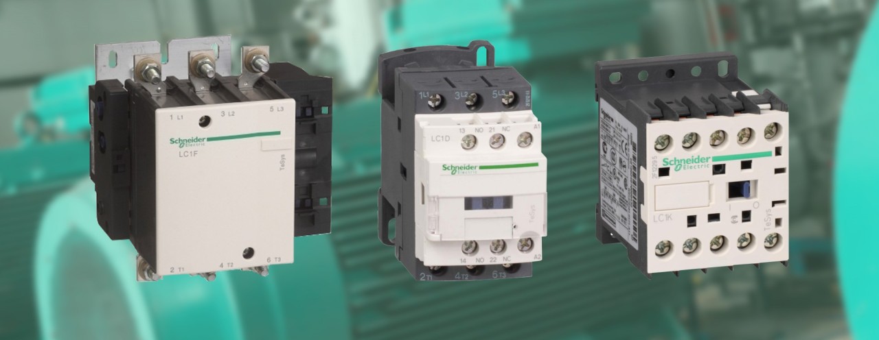
Types of contactors
Contactors can be categorized as AC contactors, DC contactors according to the usage of system voltage/power to be handled through the power poles. As AC systems in majority of applications, AC contactors may categorize according to their purpose of use. i.e. Auxiliary/Relay contactors for low power applications such as control circuit switching, signaling etc, Power contactors for load handling as we discussed above, and reversing contactors for reverser circuits (such as forward reverse). Also, according to number of poles (2pole, 3pole, 4pole) & wire connection type (screw clamp, ring lug, fast-on, spring terminals and unique terminal designs like EverLink terminals) design & application of the contactor differs. There are also product variants such as mini contactors designed for OEMs and machine integration, high power contactors for high power load applications are available in the market.
Talking about contactor construction, iron cores, an electromagnetic coil, Arc chute, Contact tips, mounting mechanism and contactor body can be identified. According to IEC 60947-5-1, its auxiliary contacts should be mechanically linked. Combination of normally open (NO) and normally closed (NC) contacts designed so that they cannot be in closed position simultaneously. As per the standard, Mirror contacts means the default NC contact is a mechanically linked, direct mirror representation of the power pole status. In other words, NC auxiliary contact cannot be in closed position at the same time if any one of the main power poles, on the same contactor is closed. This ensures the safety & reliable status monitoring.
Contactor Accessories
Instantaneous Auxiliary contact blocks can be used for various purposes such as volt free signaling/ indications, external control contacts, electrical interlocking, logic operations, self-holding etc. In addition to integrated Auxiliary blocks (number of NO/NC by default), users can plug additional blocks within imposed limitations by the manufacture. These can be selected as top/front mounted & side mounted auxiliaries.
Time Delay Auxiliary contact blocks can be used to apply time delays (on delay/off delay) on auxiliary contacts, where a time-based logic conditioning is applied. (eg; start- delta transition). These also available as add-on modules for some contactors & available to select upon the required time delay range.
Mechanical Latch Blocks can be used to keep the contactor turned on without energizing the coil continuously. Latching control may be electrical or manual.
Interference Suppressor modules are used to enable protection from undesired disturbances such as voltage spikes & switching surges. There are several types of suppressors. RC circuits (Resistor-capacitor) Effective protection for circuits highly sensitive to "high frequency" interference. For use only in cases where the voltage is virtually sinusoidal. Varistors (Peak limiting) provide protection by limiting the transient voltage, typically to 2 Uc max. freewheel diode is placed with the inductance (coil). The use of a diode is to prevent voltage spikes from arising when the power supply is disconnected. It provides a short circuit path to dissipate stored energy in the inductor.
Mechanical Interlocks in assemblies used to achieve state of two mechanisms or functions mutually dependent. Mechanical interlock may available with or without integral electrical interlock. And may be in both horizontal & vertical mounting for high power contactors.
In addition to above there are other accessories such as interface modules, power connections, mounting kits, starter assembly kits (star-delta, reversing etc), terminal spreaders, protective terminal covers, separate coils etc.
Possible causes of contactor failure?
- Contacts damaged, high contact resistance or welded
Causes may be due to; exposed to excess current flow through contacts, foreign material & environmental factors, Chattering, Improper coordination, Exceed Electrical/mechanical life
- Damaged/burnt coils
Causes may be exposed to frequency fluctuations, over voltages & transients, Chattering, Improper coil supply voltage, Insulation break due to aging
- Mechanical failures
Mechanical shock or excessive vibration, Electrodynamic forces during short circuits, Wrong Applications, Improper sizing, Improper operational parameters, Wrong selection with respect to utilization
Below are some of sample images of contactor failures

In my upcoming articles, I will be discussing the other components such as overload relays, motor protection circuit breakers, their coordination and all their technical aspects when it comes to a motor starter assembly.