

Introduction: Build 80s Style Home Computers From Scratch From Arduino Components


This project began in a rainy summer 2021 in Corona lockdown when I started to write a BASIC interpreter for Arduino from scratch. The project was simple and mainly targeted for Arduino UNO and other small systems but has now outgrown this beginnings.
This project is to show how one can build an entire standalone computer with it much like the ones which conquered the home computer market in the 80. After two less ambitious projects of building a small LCD based computer and a small computer inspired by the legendary AIM65 (Projects: How to use BASIC on Arduinos · slviajero/tinybasic Wiki (github.com)) this is the attempt to build a real computer.
The computer here is an Arduino DUE based home computer with a 7 inch 800x480 graphics display, printer support, SD card disk, a PS2 keyboard (with keymap support) or a USB keyboard (only English) and a real time clock. It includes full Arduino I/O support and an easy way to access I2C devices from the BASIC language. Optional RF24 support is available.
Alternatively a lower cost hardware design based on an Arduino RP2040 connect with an ILI9488 display is described. It is exactly compatible to the bigger system and has networking support via MQTT.
This instructable is an extension of my work in the Arduino project hub.
For more details on how this started, the interpreter architecture and BASIC in general, please take a look into my repo https://github.com/slviajero/tinybasic/wiki. There is a small manual of the BASIC interpreter and the supported hardware.
Supplies


The system is based on an Arduino DUE microcontroller. It offers enough RAM to have 64kB of BASIC memory in your home computer. The processing power of the ARM based CPU is sufficient to drive a 7 inch TFT screen.
The other essential component is the TFT screen. I use a 7 inch 800x480 SSD1936 screen. These devices are supported by the UTFT library for Arduino. Selecting a suitable screen can be tricky. You need to consult the UTFT documentation if you buy another model.
The SSD1936 is ideal because it is a 24 bit colour device.
To connect the DUE with the screen a TFT shield is needed. There are shield for Arduino MEGAs and for DUEs. These are separate models. They differ in the way the SPI bus is handled. You will need a DUE shield if you use a DUE microcontroller. This instructable also works with MEGA 256 microcontrollers. For them you need a MEGA shield.
If this setup is to heavy for you, scroll down and look at the "Build the Little Brother" section of this text. This is a fully compatible hardware design based on a low cost 3.5 inch display.
In addition to this you need two medium size breadboards, an PS2 connector, a PS2 keyboard plus some cables and a logic level converter.
You need the Arduino IDE as a software component as well as my BASIC interpreter from the repo https://github.com/slviajero/tinybasic.
Step 1: Prepare the TFT Shield and the TFT


The TFT shield will cover the upper side of the Arduino completely. No additional wires can be connected easily. There are no prototype boards on the market that work with a shield. For this reason I soldered a few wires to the shield to get access to power after mounting the microcontroller to the shield.
The blue wire is GND, the white wire is +5V and the green wire is +3.3V. There wire can be connected to a breadboard at the base of the display to provide power for the keyboard and additional devices.
My DUE shield as an own SD card slot. An old 2 GB SD card formated with a FAT filesystem serves as mass storage. Best preload the BASIC programs from the repo to have them ready once your computer is up and running. There are games, test programs and demos of the Arduino functions in three different folders in the repo.
Turning around the shield you see an important detail; DUE shields have a SPI connector in the middle of board. Unlike the MEGA 256 the SPI bus of a DUE cannot be accessed from pins 50-53. It is only reachable through the middle SPI connector. A MEGA shield will not work on a DUE as mega shield often do not have the extra SPI pins in the middle of the board.
There is one more important point when you use the TFT shield for DUEs. In the library folder of UTFT (UTFT/hardware/arm) you need to edit HW_ARM_defines.h and uncomment #define CTE_DUE_SHIELD 1. If you use other shields consult the UTFT documentation.
Step 2: Prepare the Arduino
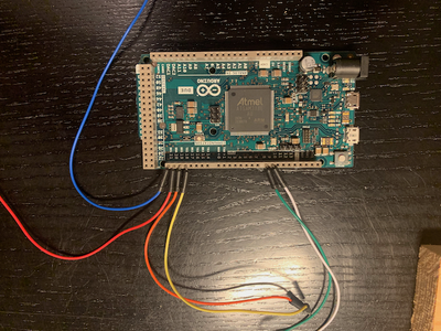


I use pins 8 and 9 to connect the PS2 keyboard, the second serial port for the printer and the I2C pins for the optional real time clock and other peripherals. Later the pins for Serial1 on the DUE will also be connected for printer and modem support.
To get access to the pins without more soldering cables can be hooked up in the DUE before the shield is connected. Pressing the DUE on the shield will hold the cables in place. This is not perfect electronics but it works. Then plug DUE and shield to the backside of the display.
I mounted my display in a little plywood frame to hold it in place.
The SD card slot on the shield is unused for a Arduino DUE. If you build the same setup with a MEGA and its suitable shield the cardslot on the shield can be used.
Step 3: Prepare the PS2 Socket


If you want to connect a PS2 keyboard, continue reading here. For an USB keyboard, skip this section.
Solder wires on your PS2 sockets following the instructions on this page https://www.pjrc.com/teensy/td_libs_PS2Keyboard.html
If you use an Arduino MEGA 256 which is a 5V machine, you are done after soldering. You can connect pin 8 of the Arduino to the clock pin of the keyboard socket and pin 9 to the data pin. Power for the keyboard comes from the GND and 5V soldered to the shield. Double check here as a wrong polarity of the power fries the keyboard.
With an Arduino DUE it is advisable to use a level converters between keyboard and the Arduino PIN as the DUE is a 3.3V system.
The GND and +5V pins and the connectors of the PS2 socket are wired to the 5V side of the level converters while GND, 3.3V power and the two Arduino pins go to the 3.3V side. Best mount the level converter on a breadboard behind the screen (see the fritzing file for details). This works to get you started. Later, all the electronics an be soldered on a board.
The initialisation of the keyboard is rather time critical. Enough power is needed to get it started. Watch the keyboard indicators on startup. If they are not blinking, try to disconnect the computer from power and reconnect it. Use a stronger power supply.
Attachments

Step 4: Use a USB Keyboard

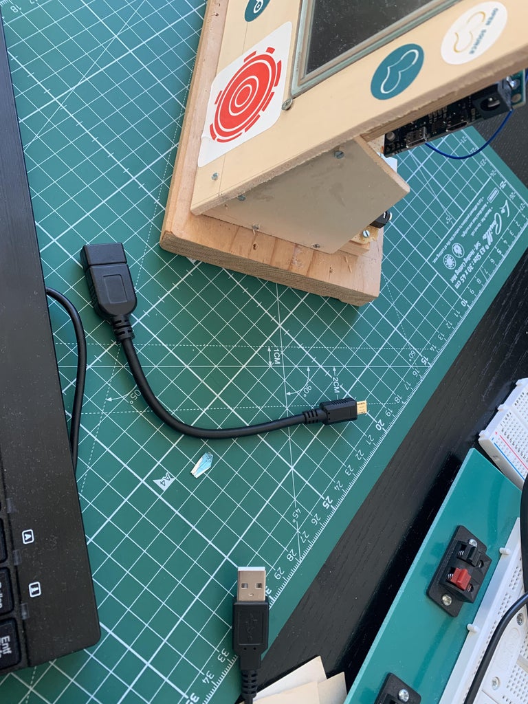
A standard USB keyboard can be used on a DUE. Use second USB port for the keyboard. This is the lower one if the DUE is mounted like shown in the picture. You might need a USB keyboard connector.
The underlying class of the Arduino SAMD core is very simple. Not all keys are supported. With an English keyboard, BASIC can be used without restrictions. All necessary keys can be accessed.
I created a German key map as well which just maps ASCII codes to one another.
Follow the instruction for USB in the instructions below.
Step 5: Upload the Software

Load the UTFT library in your Arduino IDE from the website. Also make sure that you have the actual patched version of the PS2 library (see links below). If you plan to add a clock you should also download the uRTCLib and uEEPROMLib.
Load the BASIC interpreter in the Arduino IDE. You will need the sketch https://github.com/slviajero/tinybasic/tree/main/IoTBasic together with the hardware-arduino.h and basic.h header files. Next you need to open the file IoTBasic.ino and set the language features:
#define	BASICFULL
#undef	BASICINTEGER
#undef	BASICSIMPLE
#undef	BASICMINIMAL
#undef	BASICTINYWITHFLOAT
Setting BASICFULL here will compile a BASIC interpreter with all the features. It has floating point, strings, graphics and a number of features the interpreters didn't have in the good old times. Best consult the tutorial in the repo https://github.com/slviajero/tinybasic/tree/main/examples/00tutorial for an overview. If you keep the default setting in the repo, an Integer BASIC will be compiled. This is the default for small systems.
To define the hardware features of your system, open hardware-arduino.h. Look for the section with the predefined hardware configurations
#undef UNOPLAIN
#undef AVRLCD
#undef WEMOSSHIELD
#undef MEGASHIELD
#undef TTGOVGA
#define DUETFT
#undef MEGATFT
#undef NANOBOARD
#undef MEGABOARD
#undef UNOBOARD
#undef ESP01BOARD
#undef RP2040BOARD
Define DUETFT here. Leave all the other definitions to #undef including the individual hardware settings above this section of the code.
If you want to use a USB keyboard, activate
#define ARDUINOUSBKBD
in addition to this and set USBKBDLANG to the right value.
Compile and upload to the Arduino DUE. The step of setting language and hardware features is necessary because the BASIC interpreter is scalable. It can be reduced to a very bare bone Tiny BASIC running on Arduino UNO or even 168 systems.
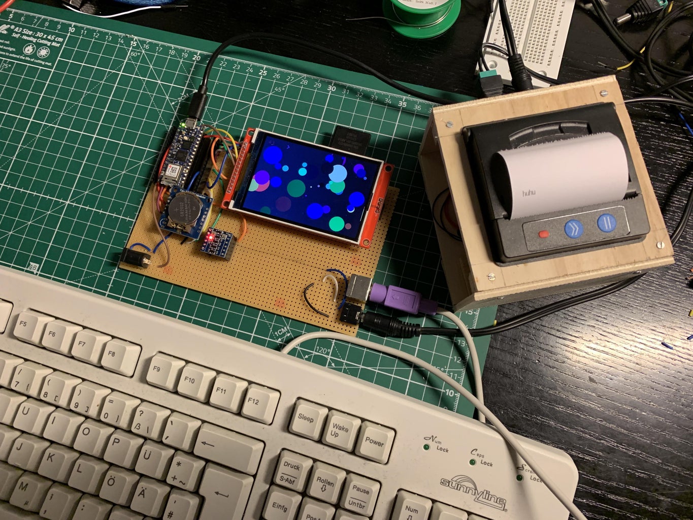
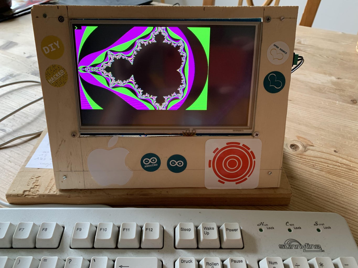
Enjoy a fully featured 64kB BASIC home computer with graphics.
The graphics output in the picture above is created by the program
10 CLS
15 I=0
20 X=RND (800)
30 Y=RND (480)
40 R0=RND (40)
42 R=RND (255):G=RND (255):B=RND (255)
43 COLOR R,G,B
50 FCIRCLE X,Y,R0
55 @X=1:@Y=1:PRINT #5;I;
56 I=I+1
60 DELAY 100
70 GOTO 20
The BASIC language is a bit different from the 80s BASIC dialects. See my wiki https://github.com/slviajero/tinybasic/wiki for more details on the features of this BASIC dialect. I ported the legendary 101 BASIC games to it and added test programs and Arduino examples. All of this is in https://github.com/slviajero/tinybasic/tree/main/examples.
The following libraries are used:
PS2 keyboard: https://github.com/slviajero/PS2Keyboard
UTFT library: http://www.rinkydinkelectronics.com/library.php?id=51
RTC: https://github.com/Naguissa/uRTCLib
My fork https://github.com/slviajero/PS2Keyboard should be used instead of the Arduino library as I added a few more features. UTFT has to be downloaded directly from the website while uRTCLib can be downloaded in the Arduino IDE library manager. I
Step 6: Use a USB Keyboard

If you don't have a PS2 keyboard or want to simplify the hardware layout, a USB keyboard can be used alternatively. The support of these keyboards on Arduino DUE is experimental and so is the BASIC integration.
Connect the USB keyboard to the lower socket of the Arduino DUE (i.e. the generic USB port as shown in the photo).
In the code change the section
#if defined(DUETFT)
#undef ARDUINOEEPROM
#undef ARDUINOPS2
#define ARDUINOUSBKBD
#define DISPLAYCANSCROLL
#define ARDUINOTFT
#define ARDUINOSD
#define ARDUINOWIRE
#define ARDUINOPRT
#define ARDUINORTC
#define PS2DATAPIN 9
#define PS2IRQPIN 8
#define SDPIN 53
#define STANDALONE
#endif
ARDUINOPS2 is undef and ARDUINOUSBKBD is defined.
Download the USBHost library from the Arduino IDE library manager. Compile and upload the code.
Currently only US English keyboards are supported as there is no keymap feature.
Step 7: Add a Real Time Clock


There is a number of clock modules on the market for Arduino projects. I have integrated the DS1307 and DS3231 library into the BASIC interpreter. The devices look like in the picture above. You need to connect it to the power lines and the SDA and SCL lines coming from the Arduino DUE. The clock can be powered with 3.3 V so no level converters are needed. I mounted mine on the little breadboard behind the display.
I don't use the standard RTC libraries from Adafruit as they bring a lot of functionality that the BASIC interpreter has anyway. Instead of these larger and commonly used library libraries, BASIC uses uRTCLib. Both can be downloaded in the Arduino IDE or directly from the github repos below.
A special array @T() is now available in BASIC: @T(0) - seconds, @T(1) - minutes, @T(2) - hours, @T(3) - day, @T(4) - months, @T(5) - year, @T(6) - weekday, @T(7) - temperature. Except temperature all array elements are read/write.
A little clock program using the array would look like this
10 CLS
20 PRINT @T(2);":";@T(1);":";@T(0)
30 PRINT @T(3);"/";@T(4);"/";@T(5)
40 PRINT "Temp:",@T(7)/100
50 DELAY 1000
60 GOTO 10
Step 8: Add a Printer

There is a large number of small thermal printers on the market. The picture shows one connected to another project of mine. These printer have serial TTL and RS232 interfaces. They need a lot of power and cannot be attached to the Arduino 5V power lines. An additional 9V power supply with at least 2A current is needed. Specs of these printers typically look like this https://github.com/slviajero/tinybasic/blob/main/misc/ThermalprinterSpecs.pdf. Identify the right pinout can be a bit of a hassle.
Connect the TX line of the printers serial port to the RX of Serial1 on the Arduino. This is pin 19. Connect RX of the printer to pin 18. Also connect the ground of the printer to ground on the Arduino. Power to the printer is connected to the external power supply via the separate power lines.
The printer appears as output device &4 in BASIC. Please consult my wiki on the syntax. Standard baudrate is 9600 which is very common for these printers.
PRINT &4, "Hello World"
should work now. Single bytes can be sent to the printer using PUT
PUT &4, 10
The I/O channel works bidirectionally.
GET &4, A
collects a byte from the printer. This can be helpful as the printers have bidirectional communication protocols.
One word of caution on voltage levels - Initially I used no level converters for the printer. It worked and there is no damage to the Arduino DUE. This is a bit risky. A level converter or even using RS232 converters would be the saver solution and will be added in the next step.
Step 9: From Breadboard to Final Solution


So far the entire computer could be build almost without soldering. This is great for trying things out but not good for a really useful computer.
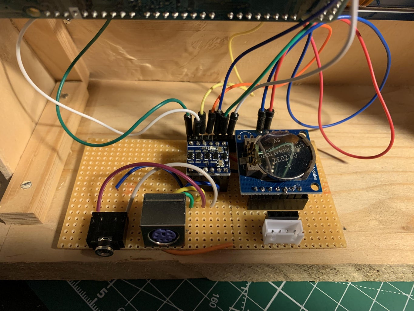
For the final setup I soldered the components to a board.
The clock is a DS1307 clock. BASIC can work with the cheaper model as well without loss of functionality. The DS1307 clock modules form factor matches better as it is quadratic and the pinout matches Grove standards. The two plugs bellow are the I2C I/O pins. You can connect 3.3V I2C peripherals here.
To the left of the clock there is the level converter. It generates 5V signals for the keyboard plugs and the TTL output of Serial1. I used a standard audio plug here which is slightly unorthodox but really practical to connect a printer or other peripherals to the computer.
Step 10: Writing Programs
Stefan's Arduino BASIC is very similar to the BASIC interpreters of the 80s with many of the features you would expect
10 PRINT "HELLO WORLD"
is the inevitable Hello World program everyone starts with. Most of the controls structures of standard Dartmouth BASIC are implemented. You can for IF THEN, FOR NEXT, GOTO, GOSUB but also the ON GOSUB and DEF FN structures known from BASIC. Variables are one letter and one number. There are strings, arrays and numbers as data types.
There are, however, a few things that are really different from other BASIC languages.
Scalability
The language can be stripped down to a minimal Palo Alto type tinybasic supporting only integers and running on Arduino UNO microcontrollers. The compile options mentioned above control how much BASIC you have. The different versions of the language are compatible. You can run any program from the smaller language set on a bigger language set.
No garbage collection
Strings are fixed memory size. They auto dimension to a maximum length of 32 but can be any length if they are created with a DIM statement. Example:
10 DIM A$(2000)
This would be string of maximum length 2000. As strings are allocated statically there is no need for a garbage collector. Similarly arrays auto dimension to length of 10.
Apple 1 BASIC style strings
There is no LEFT$, RIGHT$ and MID$. String handling is done Apple 1 style with a substring syntax. Please consult the manual on substrings for this.
In arithmetic expressions strings evaluate to the byte value of the first character.
10 A$="hello world"
20 PRINT A$(1,5)
30 PRINT A$(7,11)
Special variables, strings and arrays
@ is a valid letter in variable names. Objects with this names are special variable giving access to interpreter features. Some examples for this are:
@E() is an array stored in the EEPROM of an Arduino. Numbers can be stored in it and recalled.
@D() is the display buffer. Writing or reading from @D() put a character at a certain position in the display or recalls it.
@S is the status of the last I/O operation.
@X, @Y is the cursor position on the display.
@T() is the real time clock array.
10 PRINT "SECONDS:", @T(0)
Output and input channels
Using & plus a number redirects input and output to an I/O channel. Currently implemented channels are
&1: primary serial line
&2: keyboard and display
&4: secondary serial line (for printers)
&7: I2C wire communication
&8: RF2401 radio communication
&16: File I/O
File I/O would look like this
10 OPEN &16, "daten.txt", 1  : REM "Open file for output"
20 PRINT &16, "Hello"
30 CLOSE &16, 1
Arduino I/O function
All the basic I/O functions are available just like on C++. DWRITE and DREAD access the digital pins while AWRITE and AREAD access the analog pins. MILLIS and DELAY is implemented as well. Please read the manual on Arduino I/O for more details.
Peculiarities
The BASIC interpreter tokenises the input fully. This tokenisation makes the interpreter fast. Any kind of formating of the program text is lost after input. Listing a program always shows a standard format..
The whole memory allocation mechanism is implemented in a very lean way to make the interpreter scalable and stable. I run programs on my Arduinos for weeks without any stability problems.
There are examples for all these language features in my wiki: https://github.com/slviajero/tinybasic/wiki
More on BASIC programming
A manual with many examples can be found here https://github.com/slviajero/tinybasic/blob/main/MANUAL.md
Step 11: Programming Graphics

The BASIC interpreter has a set of graphics command that directly access the UTFT low level function.
Colour can either be set with a one parameter colour function
COLOR 128
which accepts an argument between 0 and 255.This parameter is added for compatibility with the ESP32 VGA library. It maps the value of the parameter to the 16 principal VGA colours.
Once the colour is set all other graphics and text command use this foreground colour.
Currently the following functions are implemented:
PLOT x,y: sets a pixel at x,y
LINE x0, y0, x1, y1: draw a line from (x0, y0) to (x1, y1)
RECT x,y,dx,dy: draws a rectangle at point (x,y) of size dy times dy.
CIRCLE x,y,r: draws a circle of radius r.
FRECT and FCIRCLE draw filled shapes.
The coordinate system starts at the upper left corner with the x axis going to the right and the y axis pointing to the bottom of the screen.
A classical examples for graphics is the Mandelbrot set. Type in the following program or download it from the repo
10 REM "Caculate the mandelbrot set"
20 REM "The iteration cutoff, threshold, and resolution"
30 N=10
40 T=4
50 R=200
100 C0=0: C1=0
110 CLS
200 REM "walk through the grid"
210 FOR J=2*R+1 TO 1 STEP -1
220 FOR I=1 TO 3*R+1
230 C0=-2+(I-1)/R: C1=-1+(J-1)/R
240 GOSUB 4000
250 GOSUB 5000
280 NEXT
300 NEXT
999 END
4000 REM "do an iteration on c"
4010 Z0=C0: Z1=C1
4020 FOR K=1 TO N
4030 S0=Z0*Z0: S1=Z1*Z1
4040 IF S0+S1>T THEN BREAK
4050 X0=S0-S1+C0
4060 X1=2*Z0*Z1+C1
4070 Z0=X0: Z1=X1
4080 NEXT
4090 RETURN
5000 REM "plot a point"
5010 IF K>N: COLOR 0: PLOT I,J: RETURN
5020 COLOR 255-INT(K/N*255)
5030 PLOT I,J
5040 RETURN
Increasing the iteration parameter N will add more details to the plot but will increase calculation time.
Step 12: Build the Little Brother


A SD1936 TFT with an Arduino DUE plus the additional components is a slightly expensive projects. The display can cost 60 Euros nowadays and the DUE another 40 Euros. In total the hardware cost may be at around 120 Euros.
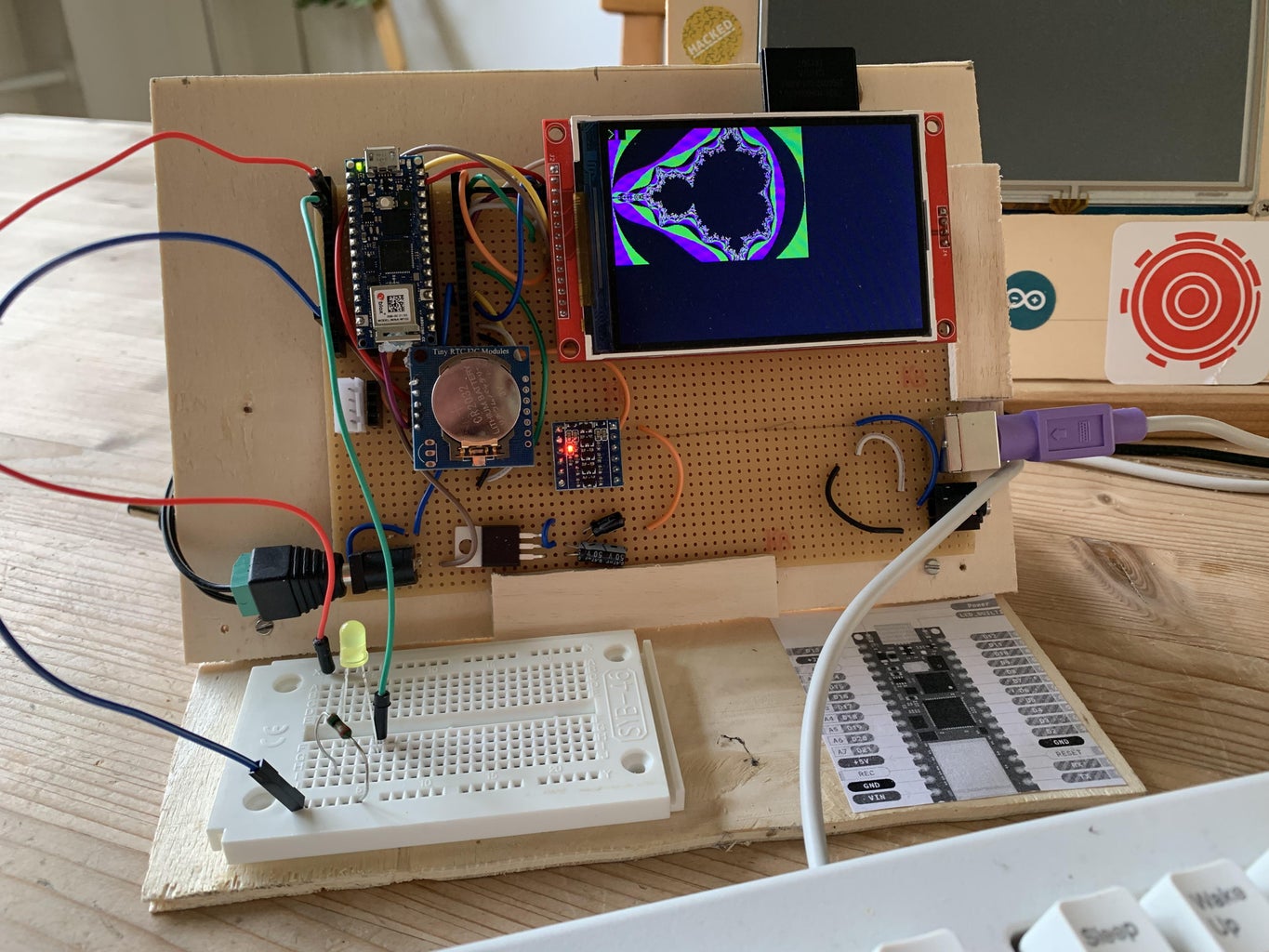
A much more cost efficient design is possible on the basis of an ILI9488 display and an Arduino RP2040 connect.
Like the big brother it has a TTL interface, plugs for I2C communication, keyboard and display.
In addition to this, RP2040 Wifi is supported in BASIC and a voltage regulator produces the 5 V for the keyboard.
The PS2 and serial port schematics are exactly identical to the DUE design. Pins 2 and 5 of the Arduino RP2040 are used for clock and data of the keyboard instead of pins 8 and 9. The RX and TX pins of the RP2040 are connected to the output plug. They are Serial1 on an RP2040 as the default Serial uses the USB device directly. Keyboard and TTL go through a voltage level converter.
The real time clock is connected to the SDA and SCL on the Arduino on pins 18 and 19.
The display is connected via the SPI bus. The default pins 11-13 are used for SCK, MISO (=CIPO) and MOSI (COPI). Pin 9 is connected to CS of the display, pin 7 to DC, and pin 7 to RST. Display brightness can be adjusted connecting A3 to the LED pin.
To compile the BASIC interpreter, use the following hardware definition in hardware-arduino.h.
#undef UNOPLAIN
#undef AVRLCD
#undef WEMOSSHIELD
#undef MEGASHIELD
#undef TTGOVGA
#undef DUETFT
#undef MEGATFT
#undef NANOBOARD
#undef MEGABOARD
#undef UNOBOARD
#undef ESP01BOARD
#define RP2040BOARD
Define RP2040BOARD here and undefine all other settings.
Download the ILI9488 library from my repo https://github.com/slviajero/ILI9488. This is a fork of Jaret Burkett's work. I will use this library to implement hardware scrolling in the future.
If you intend to use networking, open wifisettings.h and add the SSID and password of your WLAN. The WLAN parameters are compiled into the code. You will need the Arduino RP2040 network library from this from the Arduino library archive.
When the computer has started type NETSTAT to see the network connection status.
For a detailed instruction how to build the little brother, see my other instructable https://www.instructables.com/A-Arduino-RP2040-Standalone-IoT-Computer-Running-B/
Step 13: More BASIC Computers

A small and ultra low cost standalone computer can be build with the ESP8266 based Wemos D1 R1 boards plus a standard data logger shield. It is software ware compatible with the bigger system described here.
More on this can be found here: https://www.instructables.com/The-10-Euro-IoT-Computer-With-ESP-8266/
Step 14: What's Next?


This BASIC interpreter is an active project. The ESP32 micro computer with VGA output is now completed. With them you can connect your BASIC home computer to a VGA screen. Look here for more on the VGA computer.
Wifi is supported on various architetures using BASIC is a IoT endpoint. I already integrated RF2401 radio modules and run tests of home automation with them.
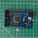
An ESP32 based epaper device is waiting to be a BASIC home computer as well as a STM32F4VE board.
There is a number of hardware designs for small basic systems where all the peripherals (SD card, PS2 plug, clock, display port) are on one prototype shield. This makes the implementation of IoT BASIC computers easy.


