
It’s been a while since I opened my first Philips CDI350 portable CD-i player and published a repair guide with capacitor list. I have already received some positive feedback that this was helpful for others fixing their players. However, part 2 of the article ended with a big question mark because some topics remained unsolved. Let’s have a look at the status of these topics and see if I can resolve them today in Philips CDI350 Repair Part 3.
1. S-Video output is not working
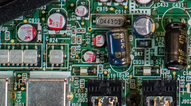
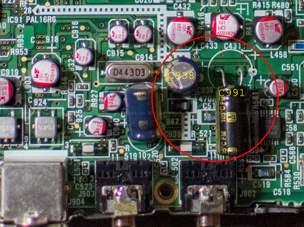
This turned out to be my fault. After carefully following the traces to and from the video encoder and comparing every component with the service manual, I noticed that I had soldered two electrolytic capacitors with the wrong polarity: C938 and C991. I can only assume that this happened because I used the + marks as indicators and not the white dots. Just look at the vast amount of plusses:
I fixed this right away by turning C991 around and replacing C938 (its value was way off). Still, there was no S-Video and also no composite video output.
Troubleshooting
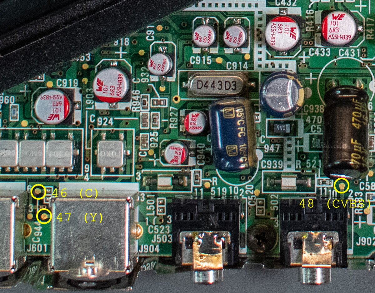
I went back to the service manual and followed the troubleshooting steps on page 65 ff. The voltages were all fine, and since I couldn’t find the measuring/test points of the separated power lines, I went on to measure the video signals. R, G and B were fine too, but S-Video and composite showed nothing at all. Again, there were some test points missing and/or labelled wrongly, so I took the ones closest to the ports connectors:
Next, I measured the voltage of every pin of the Sony CXA1145M video encoder and also watched the video signals with my oscilloscope. The voltages were all as indicated or at least very close. The S-Video signals go to a delay line (luminance / Y) and a band-pass filter (chrominance / C) and then come to a junction. One way is back into the video encoder where they are mixed and sent out again as composite video. The video signals on the encoder pins looked good with the oscilloscope. This means that at least some parts of the video circuits are still working.
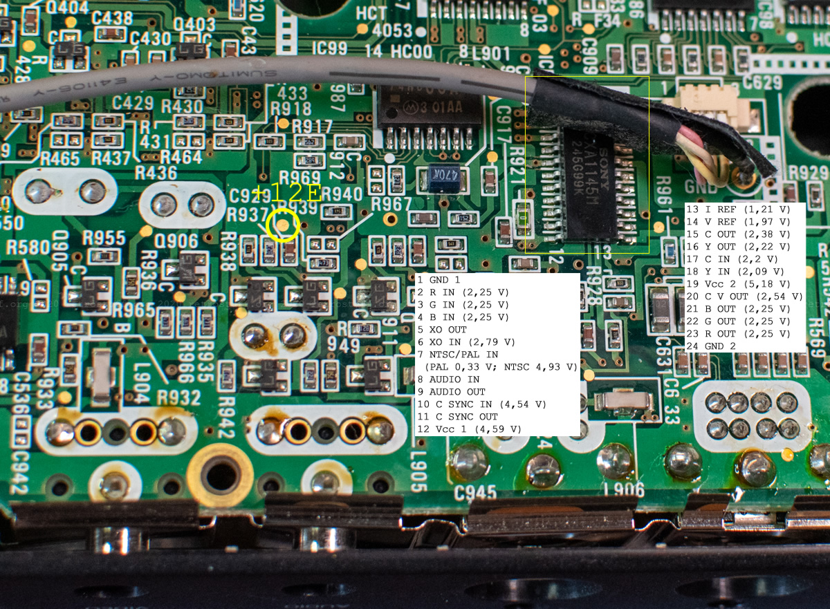
On the other side of the junctions are the luminance and chrominance output stages. In this region is also the composite video amplifier with the two capacitors that I put in the wrong way. It turned out that these circuits were supposed to be powered by a separate power line, +12E.
Fixing the power
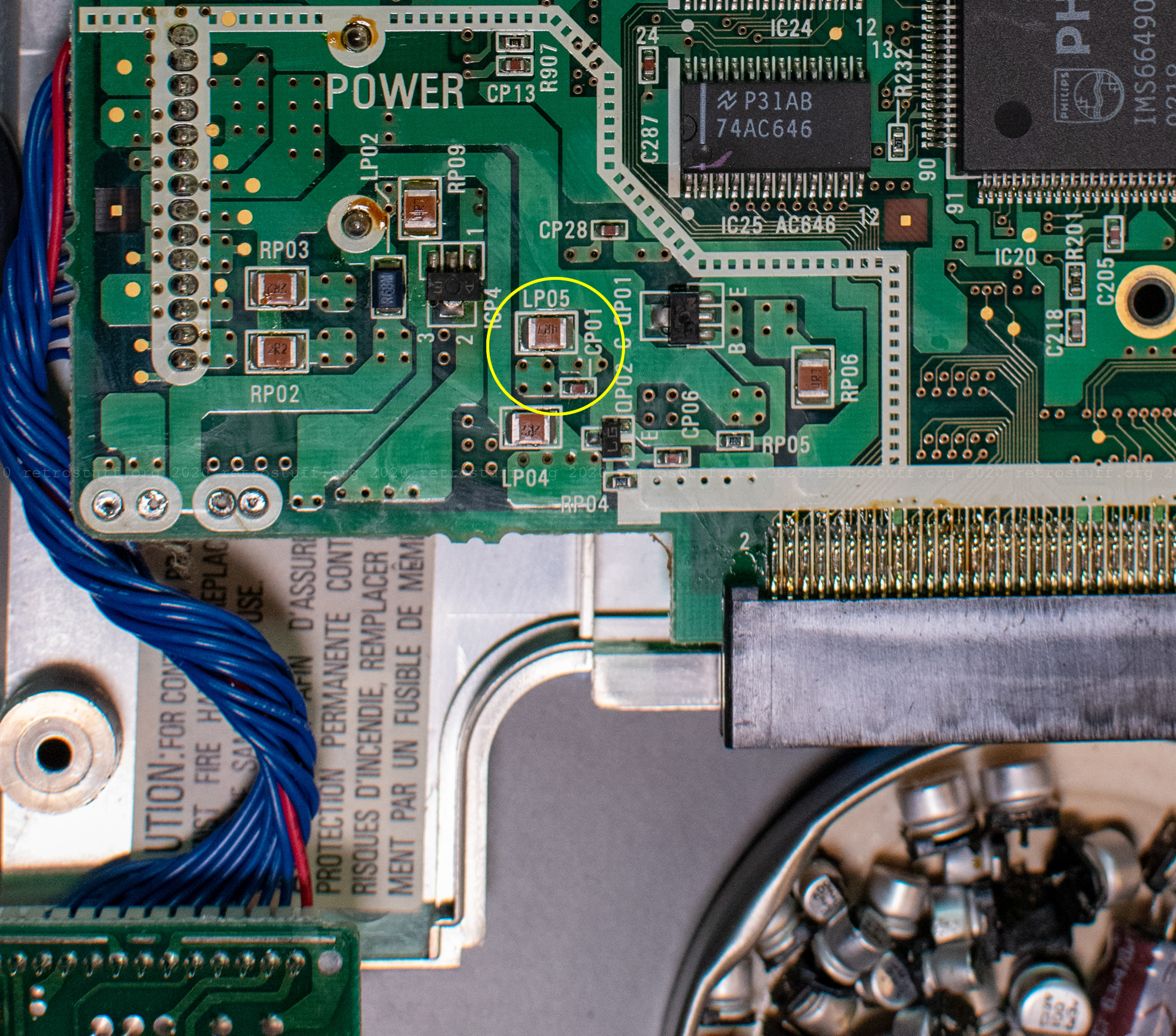
The schematics of the power section show a coil LP05 4.7 with a warning sign ⚠ that leads to +12E (TO VIDEO 2).
NOTE ON SAFETY :
Symbol ⚠ Fire or electrical shock hazard. Only original parts should be used to replace any part marked with symbol ⚠ . Any other component substitution (other than original type), may increase risk of fire or electrical shock hazard.
It seems that LP05 acted as a fuse, and indeed, the continuity test failed. As the power section is missing in the components list of the CDI350 service manual, I looked into the CDI360 service manual. LP05 is listed as 4822 158 60636 BLM32A07 FER BEADS C, a chip ferrite bead by Murata according to this site. The catalogue of Murata doesn’t seem to know this part number, nor does it offer an alternative.
So I opened up a spare CDI350 that I only kept for parts. As usual, most of the electrolytic capacitors were leaking, so I took the time to get rid of them all and clean up the PCB. Then, I removed LP05 from the bottom side (and also CP01, which turned out to be still fine) and replaced the broken part in my first CDI350. Thanks to this, the power line +12E was back and so was the video output (both S-Video and composite).
2. More capacitors
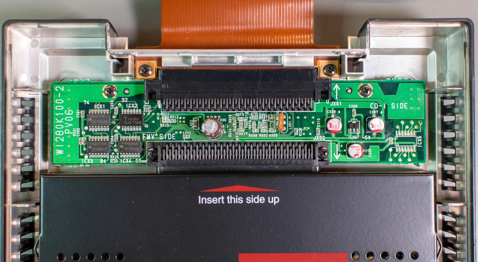
There are only three SMD and one big electrolytic capacitor in the 9142 extension module.
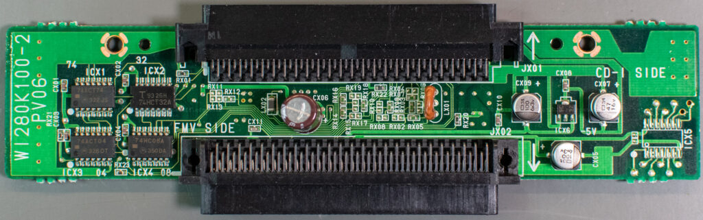
To my surprise, nothing was leaking and all of them were still fine.

I replaced the three SMD capacitors and kept the big one because I already wasted two of this type.
This is a list of additional capacitors, in case you need it. I will update it if there are more to replace (e.g. in the converter of the screen backlight or the power supply).
Additional CDI350 capacitors
| ID | F | V | Type | Size mm | Section | Part# | Replacement |
|---|---|---|---|---|---|---|---|
| CX05 | 100 µF | 6,3 V | e-cap SMD D | 6,3 x 5,5 | 9142 | ? | WCAP-AS5H 865230653011 |
| CX06 | 470 µF | 6,3 V | e-cap | 8 x 11,7; pitch 4 | 9142 | ? | Panasonic EEU-FC0J471 |
| CX07 | 47 µF | 16 V | e-cap SMD D | 6,3 x 5,5 | 9142 | ? | WCAP-AS5H 865230343004 |
| CX09 | 100 µF | 6,3 V | e-cap SMD D | 6,3 x 5,5 | 9142 | ? | WCAP-AS5H 865230653011 |
3. Clock calibration
The clock still runs fine within the stated accuracy of ± 1,53 minutes per month. Since I had replaced the original ST MK48T08B Timekeeper with a Dallas/Maxim DS1643 NV Timekeeping RAM, calibration is not possible. This has already been figured out and explained in the article Philips CD-i Timekeeper Clock Calibration.
4. RGB cable
I have already identified a suitable connector in the article IBM ThinkPad 760 Series MIDI/Game Port Adapter: It is a JAE TX20A-26PH1-D2P1-D1 plug. However, I haven’t found the time to build an RGB cable. This will happen at a later time and be featured in a new article.

3 thoughts on “Philips CDI350 Repair Part 3”