Lesson Contents
In this lesson, we’ll create a basic network with the Cisco Wireless LAN Controller (WLC) and two access points. I use a Cisco WLC 2504 and 2702 access points but any other WLC and access points will work.
I’ll explain how to configure the WLC and the switch, and we’ll take a quick look at the WLC’s GUI.
Here’s the physical topology:
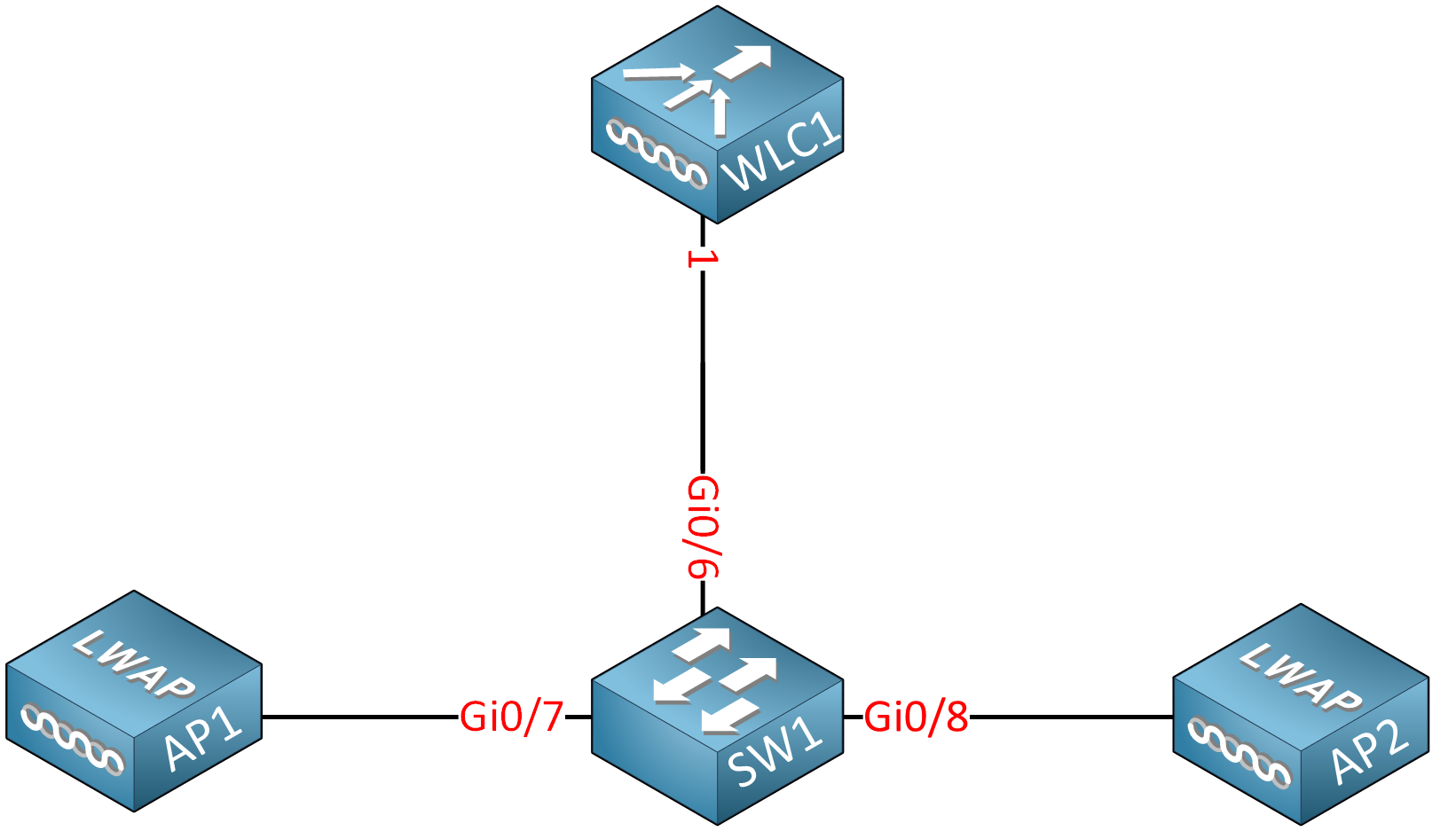
This network will have three VLANs: 10, 20, and 30:
- VLAN 10 is the management VLAN. The WLC uses the management interface to communicate with the access points, and we can use the management interface to configure the WLC through SSH or the GUI.
- VLAN 20 and 30 are for wireless networks.
We want to separate our management traffic from our wireless client traffic, which is why we have a separate management VLAN. Each SSID can map to a different VLAN so, with two VLANs, we can create two separate wireless networks. For example, you could create one wireless network for corporate users and another one for guest users.
SW1 and the WLC will have a static IP address in VLAN 10:
- WLC1: 192.168.10.100
- SW1: 192.168.10.254
We’ll configure SW1 as a DHCP server, so the access points receive a dynamic IP address. The access points will be able to find the WLC automatically because they are in the same VLAN.
Configuration
SW1
Let’s start with the switch and create those VLANs:
SW1(config)#vlan 10
SW1(config-vlan)#name MANAGEMENT
SW1(config-vlan)#exit
SW1(config)#vlan 20
SW1(config-vlan)#name SSID1
SW1(config-vlan)#exit
SW1(config)#vlan 30
SW1(config-vlan)#name SSID2
SW1(config-vlan)#exit
The WLC requires access to all three VLANs, so we need a trunk between the WLC and the switch. Let’s configure the interface:
SW1(config)#interface GigabitEthernet 0/6
SW1(config-if)#switchport trunk encapsulation dot1q
SW1(config-if)#switchport mode trunk
SW1(config-if)#switchport trunk allowed vlan 10,20,30
The interfaces that connect to the access points are access mode interfaces. I’ll add these to VLAN 10, so they can reach the management interface of the WLC directly:
SW1(config)#interface range gi0/7 - 8
SW1(config-if-range)#switchport mode access
SW1(config-if-range)#switchport access vlan 10
SW1(config-if-range)#spanning-tree portfast
SW1 is an L3 switch, so I’ll use it as a router and DHCP server in this network.
First, we enable routing globally:
SW1(config)#ip routingAnd we create the SVI interfaces, one for each VLAN:
SW1(config)#interface vlan 10
SW1(config-if)#ip address 192.168.10.254 255.255.255.0

SW1(config)#interface vlan 20
SW1(config-if)#ip address 192.168.20.254 255.255.255.0

SW1(config)#interface vlan 30
SW1(config-if)#ip address 192.168.30.254 255.255.255.0
Let’s create the DHCP pools, one for each VLAN:
SW1(config)#ip dhcp pool VLAN10
SW1(dhcp-config)#network 192.168.10.0 255.255.255.0
SW1(dhcp-config)#default-router 192.168.10.254SW1(config)#ip dhcp pool VLAN20
SW1(dhcp-config)#network 192.168.20.0 255.255.255.0
SW1(dhcp-config)#default-router 192.168.20.254SW1(config)#ip dhcp pool VLAN30
SW1(dhcp-config)#network 192.168.30.0 255.255.255.0
SW1(dhcp-config)#default-router 192.168.30.254This completes the configuration on SW1.
WLC1
Let’s take a look at our WLC. When you power it, you see the following boot messages:
WLCNG Boot Loader Version 1.0.20 (Built on Jan  9 2014 at 19:02:44 by cisco)
Board Revision 0.0 (SN: PSZ18411Q1S, Type: AIR-CT2504-K9) (P)

Verifying boot loader integrity... OK.

OCTEON CN5230C-SCP pass 2.0, Core clock: 750 MHz, DDR clock: 330 MHz (660 Mhz data rate)
CPU Cores:  4
DRAM:  1024 MB
Flash: 32 MB
Clearing DRAM........ done
Network: octeth0', octeth1, octeth2, octeth3
  ' - Active interface
  E - Environment MAC address override
CF Bus 0 (IDE): OK
IDE device 0:
 - Model: 1GB CompactFlash Card Firm: CF B61FK Ser#: C361100177A10q7EIFms
 - Type: Hard Disk
 - Capacity: 977.4 MB = 0.9 GB (2001888 x 512)


Press <ESC> now to access the Boot Menu...
I want to factory reset it, so I hit the ESC button. Depending on your software image, you see the following boot loader menu:
============================================================
 Boot Loader Menu
============================================================

 1. Run primary image (8.5.140.0) - Active
 2. Run backup image (8.0.121.0)
 3. Change active boot image
 4. Clear configuration
 5. Format FLASH Drive
 6. Manually update images

------------------------------------------------------------
I’ll select “Clear configuration”. The WLC now reboots:
Enter selection: 4
Launching...
Launching images...
init started: BusyBox v1.6.0 (2010-05-13 17:50:10 EDT) multi-call binary
starting pid 670, tty '': '/etc/init.d/rcS'

Re-building configuration filesystem
Done.

Restarting system.


WLCNG Boot Loader Version 1.0.20 (Built on Jan  9 2014 at 19:02:44 by cisco)
Board Revision 0.0 (SN: PSZ18411Q1S, Type: AIR-CT2504-K9) (P)

Verifying boot loader integrity... OK.

OCTEON CN5230C-SCP pass 2.0, Core clock: 750 MHz, DDR clock: 330 MHz (660 Mhz data rate)
CPU Cores:  4
DRAM:  1024 MB
Flash: 32 MB
Clearing DRAM........ done
Network: octeth0', octeth1, octeth2, octeth3
  ' - Active interface
  E - Environment MAC address override
CF Bus 0 (IDE): OK
IDE device 0:
 - Model: 1GB CompactFlash Card Firm: CF B61FK Ser#: C361100177A10q7EIFms
 - Type: Hard Disk
 - Capacity: 977.4 MB = 0.9 GB (2001888 x 512)


Press  now to access the Boot Menu...

Loading primary image (8.5.140.0)
100%

38645854 bytes read
Launching...
Launching images...
init started: BusyBox v1.6.0 (2010-05-13 17:50:10 EDT) multi-call binary
starting pid 690, tty '': '/etc/init.d/rcS'
Decompressing... OK
Validating...... OK
Field Extarction not supported. Deleting NBAR FE SG FILE.
Generating Secure Shell DSA Host Key ...
Starting Web Services ...
Generating Secure Shell RSA Host Key ...
Generating Secure Shell version 2 ECDSA Host Key ...
Detecting Hardware ...
Installing ether-pow driver - 0x6008


starting pid 929, tty '/dev/ttyS0': '/usr/bin/gettyOrMwar'
Setting up ZVM
Exporting LD_LIBRARY_PATH

Cryptographic library self-test....
Testing SHA1 Short Message 1
Testing SHA256 Short Message 1
Testing SHA384 Short Message 1
SHA1 POST PASSED
Testing HMAC SHA1 Short Message 1
Testing HMAC SHA2 Short Message 1
Testing HMAC SHA384 Short Message 1
passed!

XML config selected
Validating XML configuration
octeon_device_init: found 1 DPs
/dev/fpga: No such device or address
readCPUConfigData: cardid 0x6060001
Cisco is a trademark of Cisco Systems, Inc.
Software Copyright Cisco Systems, Inc. All rights reserved.

Cisco AireOS Version 8.5.140.0
Firmware Version PIC 20.0


Initializing OS Services: ok
Initializing Serial Services: ok
Initializing Network Services: ok
Initializing Licensing Services: ok

License daemon start initialization.....

License daemon running.....
Starting Statistics Service: ok
Starting Licensing Services: ok
Starting ARP Services: ok
Starting Trap Manager: ok
Starting Network Interface Management Services: ok
Starting System Services: ok
Starting FIPS Features: ok : Not enabled
Starting SNMP services: ok
Starting Fastpath Hardware Acceleration: ok
Starting Fastpath Console redirect : ok
Starting Fastpath DP Heartbeat : ok
Fastpath CPU0.00(0): Starting Fastpath Application. SDK-Cavium Networks Octeon SDK version 1.8.0, build 269. Flags-[DUTY CYCLE] : ok
Fastpath CPU0.00(0): Initializing last packet received queue. Num of cores(2)
Fastpath CPU0.00(0): Initializing Global Packet Queue. Num of packets supported(1)
Fastpath CPU0.00(0): Init MBUF size: 1856, Subsequent MBUF size: 2040
Fastpath CPU0.00(0): Core 0 Initialization: ok
Fastpath CPU0.00(0): Initializing Timer...
Fastpath CPU0.00(0): Initializing Timer...done.
Fastpath CPU0.00(0): Initializing Timer...
Fastpath CPU0.00(0): Initializing NBAR AGING Timer...done.
Fastpath CPU0.01(0): Core 1 Initialization: ok
Starting Switching Services: ok
Starting QoS Services: ok
Starting Policy Manager: ok
Starting Data Transport Link Layer: ok
Starting Access Control List Services: ok
Starting System Interfaces: ok
Starting Client Troubleshooting Service: ok
Starting Certificate Database: Initializing Curl Globally..
ok
Starting VPN Services: ok
Starting Management Frame Protection: ok
Starting DNS Services: ok
ok
Starting Redundancy: ok
Start rmgrPingTask: ok
Starting LWAPP: ok
Starting CAPWAP: ok
Starting LOCP: ok
Starting Security Services: ok
Starting OpenDNS Services: ok
Starting Policy Manager: ok
Starting Authentication Engine: ok
Starting Mobility Management: ok
Starting Capwap Ping Component: ok
Starting AVC Services: ok
Starting AVC Flex Services: ok
Starting Virtual AP Services: ok
Starting AireWave Director: ok
Starting Network Time Services: ok
Starting Cisco Discovery Protocol: ok
Starting Broadcast Services: ok
Starting Logging Services: ok
Starting DHCP Server: ok
Starting IDS Signature Manager: ok
Starting RFID Tag Tracking: ok
Starting RF Profiles: ok
Starting Power Supply and Fan Status Monitoring Service: ok
Starting Mesh Services:  ok
Starting TSM: ok
Starting CIDS Services: ok
Starting Ethernet-over-IP: ok
Starting DTLS server:  enabled in CAPWAP
Starting CleanAir: ok
Starting WIPS: ok
Starting SSHPM LSC PROV LIST: ok
Starting RRC Services: ok
Starting SXP Services: ok
Starting Alarm Services: ok
Starting FMC HS: ok
Starting IPv6 Services: ok
Starting Config Sync Manager : ok
Starting Hotspot Services: ok
Starting Tunnel Services New: ok
Starting Portal Server Services: ok
Starting mDNS Services: ok
Starting Management Services:
   Web Server:    CLI:    Secure Web: Web Authentication Certificate not found (error). If you cannot access management interface via HTTPS please reconfigure Virtual Interface.
Starting IPSec Profiles component: ok
Starting CPU ACL Logging services: ok

Enabling Controller Provisioning
 Configuring management interface
 Starting Internal DHCP server
 dhcp pool 192.168.1.3(0xc0a80103) - 192.168.1.14(0xc0a8010e), network 192.168.1.0(0xc0a80100) netmask 255.255.255.240(0xfffffff0), default gateway 192.168.1.1

 Enabling mgmt via wireless
 Enabling Provisioning SSID
 SSID: CiscoAirProvision, Admin Status: 1, Interface Name: management, 802.11 Auth: WPA2-PSK,  Wi-Fi Protected Access : Enabled
This could take a minute or two. Once the WLC has booted, you see this screen:
(Cisco Controller)


Welcome to the Cisco Wizard Configuration Tool
Use the '-' character to backup


Would you like to terminate autoinstall? [yes]:
The WLC supports an autoinstall feature that lets you download a configuration file from a TFTP server automatically. We don’t need this, so hit enter to select the default option, which is to terminate autoinstall.
We now get a wizard that asks a bunch of questions. If you see anything between brackets, then you can hit enter, and it will select the default option.
First, we set a system name, user name, and password:
System Name [Cisco_e0:4e:85] (31 characters max): WLC1
Enter Administrative User Name (24 characters max): admin
Enter Administrative Password (3 to 24 characters): ********
Re-enter Administrative Password                 : ********
We don’t need link aggregation so we’ll hit enter for the next question:
Enable Link Aggregation (LAG) [yes][NO]:Now, we need to configure the management interface:
Management Interface IP Address: 192.168.10.100
Management Interface Netmask: 255.255.255.0
Management Interface Default Router: 192.168.10.254
Management Interface VLAN Identifier (0 = untagged): 10
Management Interface Port Num [1 to 4]: 1
Management Interface DHCP Server IP Address: 192.168.10.254
Our management interface uses VLAN 10 and connects to interface one on the WLC. The following two options are less obvious:
Virtual Gateway IP Address: 192.0.2.1

Multicast IP Address: 239.1.1.1
Let me explain these two options:
- Virtual Gateway IP Address: The WLC has a virtual interface that it uses for mobility management. This includes DHCP relay, guest web authentication, VPN termination, and some other features. The WLC only uses this IP address in communication between the WLC and wireless clients. It has to be a valid IP address but shouldn’t be an IP address that is in use on the Internet or your LAN. The 192.0.2.0/24 network is assigned as “TEST-NET-1,” so it’s a safe choice.
- Multicast IP Address: The WLC uses the multicast IP address to forward traffic to APs. You have to make sure you don’t use an address that is already in use somewhere else on your network. The 239.1.1.1 multicast address is in the administratively scoped IPv4 multicast space (239.0.0.0/8), so it’s safe to use.
We also need to configure a mobility and RF group name:
Mobility/RF Group Name: mobilityThe mobility and RF group names are for WLCs that want to work together. WLCs with the same mobility group name support client roaming and redundancy between WLCs. If you use the same RF group name, WLCs can do Radio Resource Management (RRM) calculations for the entire group.
The next question is to configure an SSID:

questions: do you need to configure vlans 20 and 30 on the switch? I don’t see these int the video (just vlan interfaces) and also why do you need to specify the dhcp server (switch) in the initial setup since the clients would be getting their ip addresses from the switch presumably before connecting to the wlc? Thanks.
Hello Brad
If you simply create the VLAN interface, the VLAN itself is not created automatically. You do need to create the VLANs themselves in the configuration. These have been shown in the text of the lesson, but not in the video for brevity.
As for the DHCP server, it is necessary because the access points themselves need to receive a dynamic IP address. Once that is done, they will then automatically find the WLC since they are on the same subnet/VLAN.
I hope this has been helpful!
Laz
Why the link between SW1 and APs are access links, if vlan 10 and 20 users are connected via same AP, so will it allow traffic of both vlans???
Hello Muhammad
If you were to configure the wireless network using what is known as a “standalone architecture” then yes, you would need to create a trunk for the connection of the access point so that each SSID can correspond to the appropriate trunk. However, when using a WLC in your architecture, you eliminate the need for a trunk. WLC uses a tunnelling protocol called Control And Provisioning of Wireless Access Points (CAPWAP). This tunnels all the info necessary (VLANs, management, SSIDs etc) between the WLC and the access point. This also allows a sin
... Continue reading in our forumHi;
I try to configure this lab but i see with cisco pacKet tracer. WLC can’t have possibility to do it. Is true?
Raoul;