beatmania III
Konami (2000-2002)
🔗Known Hardware
Firebeat
- Beatmania III (GQ972)
- Beatmania III Append 6thMix (GCA21)
- Beatmania III Append 7thMix (GCB07)
- Beatmania III Append Core Remix (GCA05)
- Beatmania III The Final (GCC01)
🔗Known Parts
🔗Images and Diagrams
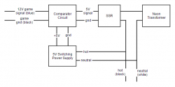
Block diagram for controlling replacement neon transformers.
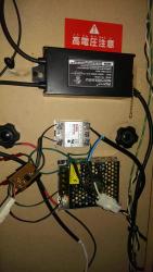
Finished neon circuit.
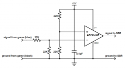
Comparator schematic.
🔗Repair Manuals
🔗Repair Tips
🔗 Dimmable Neons
Beatmania III is unique to any other game I've seen in that it has dimmable neons. In the service menu when testing the lamps, you'll notice that the neon setting for both sides goes from 0-63. On an original cabinet with no replacement parts, off (or 0) will be completely off, 63 will be completely on and the rest of the numbers will make the neon brightness change with respect to the number. The original transformers tend to go bad and have been sealed with epoxy for some reason, so repairing them seems impossible. It is possible to hook up a regular neon transformer with a solid state relay (SSR) to allow the game to at least turn on/off the neons. The idea is to pick a game value (I chose 32) to be on. Any value equal or greater to this should turn the neons on, and any value less than this should turn the neons off.The original connections included AC hot and neutral, as well as a 12V DC and GND signal wire (four in total) going to the transformer. Note that it is not as easy as hooking the signal/ground directly into the SSR to switch the AC hot, since the voltage is effectively reversed. When measuring on my cabinet, a setting of 0 in the menu produced 11.24V on the signal wire, and 63 produced 0.0V. I measured the voltage value for each setting in the service menu and found that the equation
voltage = 11.24 - (0.182 * setting) fits the behavior almost exactly. The problem with this signal is that the neons have to be on when the voltage is less than some amount and off when they are greater than some amount. Passive SSRs only switch on when a voltage exceeds their threshold, so wiring directly to an SSR will get you neons which are inverted.I tried inverting the output signal from the SSR using a mechanical AC relay using the normally closed connections. This worked, but there was a loud click from the relay whenever the neon was switched on or off, and there was a small delay (on the order of 10s of milliseconds) between the game wanting to switch the neons and the neons actually switching. For a rhythm game where the neons flash to the beat, this wasn't acceptable. In order to do the logic conversion on the signal line, there needs to be DC power (12V or 5V doesn't matter since you can use a simple voltage divider to convert the signal from the game to whatever range you want). I didn't want to run a line from the power supply in the game up to the speakers because it would add additional non-standard connectors to the speaker connections and make it harder to disassemble or move the game. So I decided on purchasing small 5V switching regulated power supplies and connecting them to the AC line used to power the neons. Then, I divided the game voltage from 12V to 5V using a resistors and fed that to a comparator circuit as included above. Using the 5V from the power supply to power the circuit as well as provide the reference voltage to compare allowed me to use the trim pot on the power supply to adjust the circuit to turn on at exactly 32 and off at exactly 31 in the service menu. A block diagram of this setup is included above.Note that with this approach, you want to tune both sides so that when 32 is selected in the game the indicator light on the SSR is fully lit, and when 31 is selected the indicator is fully extinguished. If it is partially lit, you might get flickering at that value. Also, since the game attempts to use the dimming feature, if you have the thresholds set differently, the neons will come on and turn off at slightly different times which doesn't look as good. Also note that it is recommended to use the same neon transformer on both sides or the electrical characteristics of different neon transformers could also cause the neons to flash slightly out of sync from each other. For my conversion, I used two CoolNeon NG.A206GL 6kV 30mA neon transformers. The final result can be seen above. I used the original connectors from broken original transformers to avoid chopping up the wiring inside the speakers.🔗 Replacement Screw Specification
Here is a partial list of screws found on a Beatmania III.
- Deck screws - Flat countersunk black oxide M4 0.7mm thread pitch 16mm length screws [1]
🔗 Refurbishing Jittery Effector Knobs
The rotary knob encoders that's used on the EFX boards inside the effector panel are obsolete and there are no known replacements. The good news is that they are possible to service in order to refurbish them to new. If your knobs are jittery or jump several positions when you turn them just a little bit, or barely function at all, you can repair them.To get at the boards, you'll want to remove the panel from the control deck using the 6 screws around the border, unplug all of the buttons and connectors and unscrew the grounding wires. Now, you can take the panel where its easier to work on. The knobs can be removed using a small hex key to loosen a set screw embedded into the side of each knob. Then, a hex nut and washer hold the encoders tightly to the panel. Remove those. Now, flip over the board and remove the four nuts securing the boards from the rear. Once all this is removed you should be able to pull the boards straight back out. Sometimes they get stuck due to spills on the cabinet.Now, with a board in hand, we're going to take apart the encoders and refurbish them inside. You'll need some isopropyl alcohol (99% preferred), a pink eraser, a small flathead screwdriver (preferably from a jewelers kit), a needle-nose pliers and some compressed air. Take the small screwdriver and push out the four metal tabs clamping the plastic top down (example). You will need to bend them outwards enough to lift the plastic top straight off (example). Now, with the two pieces removed, you should be able to see the minuscule pins responsible for reading the encoder plate (example), as well as the encoder plate on the bottom of the encoder shaft (example). Both of these are likely tarnished. Be careful not to touch the round metal contact that's separate from the three encoder pins as this is responsible for making a knob clicky or free-spinning. Spray isopropyl alcohol on the contacts and very gently rub them with a pink eraser. Then, spray more isopropyl alcohol and blast the area with compressed air. This should remove any pink eraser bits and dry the inside of the encoder. Now, spray isopropyl alcohol on the bottom of the knob and use the pink eraser to vigorously clean the metal part of the knob. Use more isopropyl alcohol to wash the area and then spray it dry again with the compressed air. If done right, the pins and the encoder plate will be a shiny silver with no tarnish or dirt (example). Before reassembling I bend the three reader pins up slightly to make better contact with the encoder plate, then place the plastic top back straight down onto the enclosure. Make sure the orientation of the plastic is the same as when you removed it so that the top of the plastic key lines up with the hole in the metal effector panel itself. Hand-push the four metal tabs back to secure the top and plug the board into your beatmaniaIII to test it for correct operation in the test menu. If it is still jittery, clean all of the metal bits inside again. Once you're satisfied you can tightly squeeze the tabs back onto the plastic body using needle-nose pliers.Now, you can re-assemble the panel the same way you disassembled it. Now is also a good opportunity to scrub dirt out of the recessed text using isopropyl alcohol and a toothbrush. Make sure to install the washers before you put the hex nuts back around the encoders so as to help keep future spills from getting on the EFX boards.