The CABRI research reactor
The CABRI facility is a pool-type research reactor (basic nuclear installation (INB) no. 24) operated by the CEA and located at the Cadarache centre in the Bouches-du-Rhône department. It is dedicated to the study of envelope accident situations for certain reference accidents taken into consideration in the safety analysis of pressurised water reactors (PWRs).
The CABRI facility
In its current configuration¹, the CABRI research reactor can simulate a large and very rapid increase in power - also known as a power transient - representative of reactivity accidents (RIA: Reactivity Initiated Accident) that must be taken into account in the safety analysis of PWRs.
(1) CABRI could be adapted in the future to study the behaviour of a fuel rod during a loss of coolant accident (LOCA).

More specifically, it is used to study the behaviour of fuel rods and their possible failure during such accidents. Together with its partners, IRSN specifies the tests that best reproduce the conditions of such accidents in order to test the selected fuels. It finances the experimental programmes and the operation of the CABRI reactor in which the tests are carried out by a joint IRSN/CEA team of experimentalists. IRSN also carries out pre- and post-test examinations on the test rod.
At the same time, a number of pieces of experimental equipment have been replaced (test device handling hood and transport hull) or renovated (IRIS non-destructive examination station, seismic reinforcement of the in-line fuel displacement measurement system, the hodoscope).
The most important modification, on the experimental side, is the replacement of the sodium test loop by a pressurised water loop (PWL), which reproduces the thermal-hydraulic conditions of a pressurised water reactor (280°C, 155 bar, water velocity around the test rod of 4 m/s), the type of reactor used in France's nuclear fleet.
A major overhaul of the facility, financed by IRSN and managed by CEA, took place over 12 years (from 2003 to 2015), resulting in a safety upgrade (particularly with regard to seismic risk and fire risk) and numerous functional improvements: renovation of the reactor core cooling circuit and effluent circuits, renovation of the core block and transient rod fast-acting valves, replacement of the nuclear ventilation and monitoring/command of the facility and equipment, etc.
The CABRI reactor core
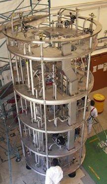
With a maximum power of 25 MW in steady-state operation, the feeder core (figure below), made up of 1,487 stainless steel clad UO2 rods (enriched to 6%), is very compact (65 cm square, 80 cm high). In static operation, it is controlled by 6 hafnium control and safety rods (BCS) (6 groups of 23 natural hafnium rods).
It is crossed at its centre by the experimental cell of the pressurised water loop (EP cell) in which the device containing the test rod subjected to the power transient is located. The feeder core also has a horizontal irradiation channel through which a device called a hodoscope can measure fuel movements in real time during the power transient. These live measurements are supplemented after the test by non-destructive examinations of the test rod carried out in the IRIS station (gamma-scanning and X-ray imaging).
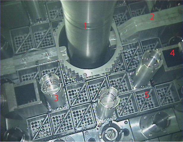
The heart of CABRI :
1 - EP experimental cell
2 - Irradiation channel
3 - Control and safety bar (BCS)
4 - Transient rod
5 - Fuel assembly
Reactivity injection system
One of the main particularities of the reactor is its reactivity injection system which is used to perform the power transient. The type of reactivity-initiated accident considered for a PWR as part of safety assessments is the ejection of a control rod following the failure of a drive mechanism casing due to the difference of the pressure between the inside of the vessel, 155 bars, and the outside, which is at the ambient pressure of the reactor building. The very rapid increase in reactivity which results is recreated inside the Cabri reactor using four “transient rods” located in the core. Each transient rod is composed of 24 tubes which cover a reduced fuel assembly of 5×5 UO2 rods.
Before the test, the transient rods are filled with helium-3, a neutron-absorbing gas, at a pressure of approximately 10 bar. The power transient is generated, when the reactor is at a virtually nil power level (100 kW, typical of hot shutdown of a PWR), with controlled opening of the fast valves so the helium-3 under pressure can escape; this results in a sudden increase in reactivity (since the neutrons are no more absorbed) and thus to a power peak (or pulse). This is immediately limited by neutron counter-reactions, primarily Doppler effect, and then terminated by the controlled dropping of the control rods in order to adjust the energy delivered to the test rod. During the power transient, the neutron safeguards of the reactor are inhibited for 1 second. The pulses last from several milliseconds to several tens of milliseconds (characterized by width at mid-height between 8 and 80 ms), with total instantaneous power that can exceed 21 GW, and energy deposited in the core reaching 237 MJ. The test director operates the digital and analog system for control of transient rods, which controls the transient rod depressurization process.
Pressurized water loop
The pressurized water loop is a test loop passing through the center of the Cabri core. The pressurized water loop replaces the previous experimental sodium loop. Its role is to house the test device and create the thermal hydraulic conditions around the test rod that are those of a PWR: 280°C, 155 MPa and a maximum flowrate of ~4 m3/h.

The pressurized water loop thus constitutes the first safety barrier of the facility with regard to the rod being tested. The part of the pressurized water loop located at the center of the reactor is termed the in pile pressurized water cell. It is connected to the out of pile containment vessel which houses all of the components producing PWR thermal hydraulic conditions (pressurizer, circulation pump, heat exchangers) and the related systems of the pressurized water loop (relief tank, systems for managing liquid and gas effluent generated during testing, etc.).
Since water in the pressurized water loop may be contaminated, it is placed in a double shell, which constitutes the second containment barrier. The loop includes a filter for trapping fine fuel fragments that may have been released (to protect the pump and limit source term in the effluent). The part at the core of the double shell is known as the security tube. The assembly containing the security tube and in pile pressurized water cell is the pressurized water cell. The containment and security tube are made of Zircaloy-4 to optimize neutron transparency around the test rod. The part of the pressurized water loop connecting the in pile pressurized water cell to the out of pile containment vessel has lead shielding for radiation protection.
Hodoscope
The hodoscope is another specific feature of the Cabri facility. IRSN’s almost unique measurement equipment² monitors the movements of the test rod fuel in real time.
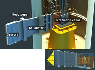
The hodoscope is located in the axis of the reactor core. The collimator channels neutrons from the test fuel to the detectors. The collimator crosses the reactor pool inside a leaktight sleeve towards the test cell in which the test fuel is located. Rotations of the collimator are used to align it on the test rod. Its characteristics: 3 meters long, 5 metric tons and the front side of the collimator is 1,020 mm from the core axis.
(2) The Transient Reactor Test (TREAT) facility at the Idaho National Laboratories in the United States is also equipped with a hodoscope, but it has not been in use for a number of years and its detectors have a different design.
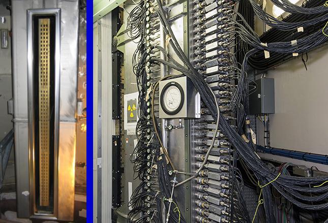
The collimator corresponds to a matrix of measurement windows over three columns each having 51 rows for a total of 153 measurement windows (picture on the left). Each window (picture on the right) includes a recoil proton counter and fission chamber for a total of 306 neutron counting tracks. The detectors sense only rapid neutrons from the test rod at a maximum acquisition rate of 1 ms.
The hodoscope thus provides the power profile of the test rod in real time. It measures elongation and detecting any relocation of the fuel.
IRIS station
IRSN’s facility for radiography, imaging and spectrometry (IRIS) is a measurement station for nondestructive examinations of rods tested in the Cabri reactor that supplements the direct measurements of the hodoscope before and after the test. The objectives are to characterize the degradation of the test rod following the power pulse and to quantify the distribution of fission products.
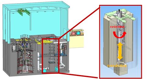
For this the IRIS station includes a shaft that is 1-meter square and 11 meters deep with a motorized sleeve in which the device containing test rod is inserted. An elevator is used to move the device in front of two examinations lines of sight (gamma scanning line of -5 m and X-ray imaging line of sight at -8 m).
Two types of nondestructive tests are performed on test rods in the Cabri reactor: gamma scanning and X-ray imaging measurement.

Gamma scanning
Quantitative measurement of the linear gamma activity profile of the fission and/or activation products found in the test rod.
X-ray imaging measurement
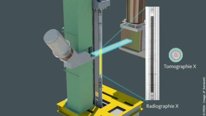
X-rays are generated by a linear electron accelerator located at two different levels of the facility. The accelerator bunker which generates the HF wave is located on level 0. The HF wave is transmitted using a wave guide to the X-ray head, located at -8 m and which is used to accelerate electrons that will reach a tungsten target creating X-rays by bremsstrahlung. The X-ray beam is produced with a dose rate of 13 Gy/minute at 1 meter and a maximum energy of 8 MeV.
- Measurement of the attenuation of an X-ray generated by an accelerator, transmitted through the device then captured by the camera:
- X-ray tomography uses the rotating movement of a device to obtain a quantitative mapping of the density over a cross section of the test device,X-ray radiography uses the traveling movement of the device.